EP1769738A1 - Dispositif pour mesurer la pression d'un fluide de manière invasive - Google Patents
Dispositif pour mesurer la pression d'un fluide de manière invasive Download PDFInfo
- Publication number
- EP1769738A1 EP1769738A1 EP06076727A EP06076727A EP1769738A1 EP 1769738 A1 EP1769738 A1 EP 1769738A1 EP 06076727 A EP06076727 A EP 06076727A EP 06076727 A EP06076727 A EP 06076727A EP 1769738 A1 EP1769738 A1 EP 1769738A1
- Authority
- EP
- European Patent Office
- Prior art keywords
- fluid
- diaphragm
- contacting area
- pressure
- fluid contacting
- Prior art date
- Legal status (The legal status is an assumption and is not a legal conclusion. Google has not performed a legal analysis and makes no representation as to the accuracy of the status listed.)
- Withdrawn
Links
- 239000012530 fluid Substances 0.000 title claims abstract description 137
- 230000004044 response Effects 0.000 claims abstract description 6
- 238000000034 method Methods 0.000 claims description 17
- 239000000463 material Substances 0.000 claims description 8
- 238000001631 haemodialysis Methods 0.000 claims description 4
- 230000000322 hemodialysis Effects 0.000 claims description 4
- 238000001802 infusion Methods 0.000 claims description 4
- 230000008859 change Effects 0.000 claims description 3
- 210000001124 body fluid Anatomy 0.000 claims description 2
- 239000010839 body fluid Substances 0.000 claims description 2
- 238000011109 contamination Methods 0.000 description 3
- 238000005259 measurement Methods 0.000 description 3
- 230000036772 blood pressure Effects 0.000 description 2
- 230000036512 infertility Effects 0.000 description 2
- 238000012544 monitoring process Methods 0.000 description 2
- 239000000565 sealant Substances 0.000 description 2
- 238000007789 sealing Methods 0.000 description 2
- XUIMIQQOPSSXEZ-UHFFFAOYSA-N Silicon Chemical compound [Si] XUIMIQQOPSSXEZ-UHFFFAOYSA-N 0.000 description 1
- FAPWRFPIFSIZLT-UHFFFAOYSA-M Sodium chloride Chemical compound [Na+].[Cl-] FAPWRFPIFSIZLT-UHFFFAOYSA-M 0.000 description 1
- 229910052782 aluminium Inorganic materials 0.000 description 1
- XAGFODPZIPBFFR-UHFFFAOYSA-N aluminium Chemical compound [Al] XAGFODPZIPBFFR-UHFFFAOYSA-N 0.000 description 1
- 239000008280 blood Substances 0.000 description 1
- 210000004369 blood Anatomy 0.000 description 1
- 230000007423 decrease Effects 0.000 description 1
- 230000003247 decreasing effect Effects 0.000 description 1
- 238000013461 design Methods 0.000 description 1
- 201000010099 disease Diseases 0.000 description 1
- 208000037265 diseases, disorders, signs and symptoms Diseases 0.000 description 1
- 238000006073 displacement reaction Methods 0.000 description 1
- 239000013013 elastic material Substances 0.000 description 1
- 239000000835 fiber Substances 0.000 description 1
- 230000005484 gravity Effects 0.000 description 1
- 230000036541 health Effects 0.000 description 1
- 239000007788 liquid Substances 0.000 description 1
- 230000007246 mechanism Effects 0.000 description 1
- 229910052751 metal Inorganic materials 0.000 description 1
- 239000002184 metal Substances 0.000 description 1
- 150000002739 metals Chemical class 0.000 description 1
- 230000002265 prevention Effects 0.000 description 1
- 229910052710 silicon Inorganic materials 0.000 description 1
- 239000010703 silicon Substances 0.000 description 1
- 239000011780 sodium chloride Substances 0.000 description 1
- 229910001220 stainless steel Inorganic materials 0.000 description 1
- 239000010935 stainless steel Substances 0.000 description 1
- 239000000126 substance Substances 0.000 description 1
- 229920001169 thermoplastic Polymers 0.000 description 1
- 239000004416 thermosoftening plastic Substances 0.000 description 1
Images
Classifications
-
- A—HUMAN NECESSITIES
- A61—MEDICAL OR VETERINARY SCIENCE; HYGIENE
- A61B—DIAGNOSIS; SURGERY; IDENTIFICATION
- A61B5/00—Measuring for diagnostic purposes; Identification of persons
- A61B5/02—Detecting, measuring or recording for evaluating the cardiovascular system, e.g. pulse, heart rate, blood pressure or blood flow
- A61B5/021—Measuring pressure in heart or blood vessels
- A61B5/0215—Measuring pressure in heart or blood vessels by means inserted into the body
-
- A—HUMAN NECESSITIES
- A61—MEDICAL OR VETERINARY SCIENCE; HYGIENE
- A61M—DEVICES FOR INTRODUCING MEDIA INTO, OR ONTO, THE BODY; DEVICES FOR TRANSDUCING BODY MEDIA OR FOR TAKING MEDIA FROM THE BODY; DEVICES FOR PRODUCING OR ENDING SLEEP OR STUPOR
- A61M1/00—Suction or pumping devices for medical purposes; Devices for carrying-off, for treatment of, or for carrying-over, body-liquids; Drainage systems
- A61M1/36—Other treatment of blood in a by-pass of the natural circulatory system, e.g. temperature adaptation, irradiation ; Extra-corporeal blood circuits
- A61M1/3621—Extra-corporeal blood circuits
- A61M1/3639—Blood pressure control, pressure transducers specially adapted therefor
- A61M1/3641—Pressure isolators
-
- A—HUMAN NECESSITIES
- A61—MEDICAL OR VETERINARY SCIENCE; HYGIENE
- A61M—DEVICES FOR INTRODUCING MEDIA INTO, OR ONTO, THE BODY; DEVICES FOR TRANSDUCING BODY MEDIA OR FOR TAKING MEDIA FROM THE BODY; DEVICES FOR PRODUCING OR ENDING SLEEP OR STUPOR
- A61M1/00—Suction or pumping devices for medical purposes; Devices for carrying-off, for treatment of, or for carrying-over, body-liquids; Drainage systems
- A61M1/36—Other treatment of blood in a by-pass of the natural circulatory system, e.g. temperature adaptation, irradiation ; Extra-corporeal blood circuits
- A61M1/3621—Extra-corporeal blood circuits
- A61M1/3639—Blood pressure control, pressure transducers specially adapted therefor
Definitions
- the present disclosure relates generally to devices for measuring fluid pressure, and more particularly to devices for invasively measuring fluid pressure.
- non-disposable devices may include electronic sensors that have a saline buffer between the fluid and the sensor.
- a non-disposable fluid pressure measuring devices One potential problem with non-disposable fluid pressure measuring devices is that the spread of disease may be substantially difficult to control.
- Various fluid-pressure devices use fluid (liquid or gel), generally contained between two diaphragms, as the media to transmit the pressure to the sensor that monitors pressure. One of the diaphragms conforms responsive to the pressure received, while the other contains the fluid.
- diaphragms used in hemodialysis or infusion blood-pressure devices are in an elastic condition, which generally requires calibration between uses. These devices generally use both: well-controlled materials for the diaphragm and/or mounting of the diaphragm; and a calibration procedure that accounts for mounting and material variability. Such materials and calibration generally undesirably add to the expense of the device and efficiency of use thereof.
- a device for invasively measuring fluid pressure includes a disposable housing having a fluid contacting area and a non-fluid contacting area.
- a disposable diaphragm in a substantially non-elastic state is disposed within the housing and separates the fluid contacting area from the non-fluid contacting area.
- a side of the diaphragm is adapted to contact the fluid, and the diaphragm has sufficient flexibility to move a distance axially within the non-fluid contacting area in response to fluid contact. The distance is substantially proportional to the fluid pressure.
- An electronic sensing device is removably attached adjacent the non-fluid contacting area of the housing, and is spaced from the diaphragm. The electronic sensing device is capable of determining the fluid pressure.
- Embodiment(s) of the device and method disclosed herein advantageously allow the invasive measuring of fluid pressure during procedures, such as, for example, hemodialysis or infusion, while substantially aiding in avoidance of bio-contamination of the sensor.
- a disposable housing as defined herein may substantially aid in maintaining the sterility of the device use, while allowing the more costly sensor and accompanying electronics to be reused.
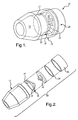
- the device 10 for invasively measuring fluid (a non-limitative example of which is body fluid) pressure is depicted.
- the device 10 includes a disposable housing 12 having a fluid contacting area 14 and a non-fluid contacting area 16.
- the housing 12 may have any suitable geometry, configuration, and/or may be molded with fittings for various applications.
- the device 10 may be utilized in any application that requires a method that substantially prevents contamination from one set of measurements to the next. This type of method is typical in many medical, biological, and/or chemical applications.
- the housing 12 generally has a substantially frusto-conical shape. Further, it is contemplated as being within the purview of the present disclosure that the housing 12 may be made of any suitable material, including, but not limited to metals (non-limitative examples of which include aluminum and stainless steel), engineering grade thermoplastics, and/or combinations thereof.
- a disposable diaphragm 18 in a substantially non-elastic state/condition is operatively disposed within the housing 12.
- the diaphragm 18 is sealingly engaged within the housing 12 such that it separates the fluid contacting area 14 from the non-fluid contacting area 16.
- the diaphragm 18 is sealingly engaged with the housing 12 to substantially prevent fluid from entering the non-fluid contacting area 16. It is to be understood that embodiment(s) of the device 10 may still function if fluid enters the non-fluid contacting area 16, depending, at least in part, on the amount of fluid in the area 16, the type of fluid in the area 16, and the sensor used.
- One side 17 of the diaphragm 18 is adapted to contact the fluid. It is to be understood that the diaphragm 18 has sufficient flexibility to move a distance axially within the non-fluid contacting area 16 in response to fluid contact with the fluid contacting side 17. In an embodiment, the axial distance moved by the diaphragm 18 is substantially proportional to the fluid pressure exerted on the fluid contacting side 17 of the diaphragm 18.
- the diaphragm 18 may be formed from any suitable material, depending at least in part upon the particular application in which the device 10 is desired for use.
- the diaphragm 18 in a substantially non-elastic state is formed from various elastomeric materials.
- substantially non-elastic state/condition refers to a sufficient flexibility of the diaphragm 18 that allows it to move in a predetermined direction, and substantially remain in that extended position, without being completely elastic.
- the diaphragm 18 may move without stretching its material fibers.
- the disposable diaphragm 18 in its non-elastic state substantially eliminates calibration steps (e.g. those that take into account the force needed to stretch an elastic material) generally required with a diaphragm in an elastic state. It is to be understood that the force used to move the diaphragm 18 in its non-elastic state remains substantially constant. Once a diaphragm enters its elastic state, an increase in force over a linear displacement may be required.
- the device 10 contains an electronic sensing device 22.
- the electronic sensing device 22 is operatively housed in a base 20 that is removably attached adjacent the non-fluid contacting area 16 of the housing 12. Sensing device 22 is spaced from the diaphragm 18. It is to be understood that the base 20, which contains the electronic sensing device 22, may be mounted directly in or on the medical device (not shown) being used; or base 20 may be an external mechanism that is electrically connected to the medical device through a wired or wireless connection.
- the base 20 is removeably attached to the housing 12 via any suitable means, including but not limited to snap fit, interference fit, threading engagement, quick connects, and/or combinations thereof.
- the non-fluid contacting area 16 is substantially sealed away from the ambient environment and the fluid.
- the non-fluid contacting area 16 is sealed by a combination of the housing 12, a non-fluid contacting side 19 of the diaphragm 18, and the electronic sensing device 22.
- the electronic sensing device 22 is capable of determining the pressure of the fluid that contacts the diaphragm 18.
- the electronic sensing device 22 includes pressure sensors, such as silicon based piezo or microelectromechanical (MEMS) devices, or strain type measurement systems.
- MEMS microelectromechanical
- Fig. 2 depicts the following elements as described above: housing 12, diaphragm 18, base 20, and electronic sensing device 22.
- a sealing member 24 is shown. Sealing member 24 serves as a sealant between the housing 12 and the base 20. It is to be understood that seal member 24 may be formed from any suitable sealants.
- seal member 24 includes at least one of O-rings, non-permeable die cut or molded gaskets, and/or combinations thereof.
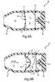
- the device 10 is shown in an embodiment of a pre-use (Fig. 3A) and use (Fig. 3B) state.
- the housing 12 of the device 10 is placed in contact with the fluid (e.g. blood), the pressure of which is to be invasively measured.
- Fluid contacts at least a portion of the fluid contacting side 17 of the diaphragm 18, thereby moving the diaphragm 18 axially within the non-fluid contacting area 16 to equalize the pressure in the non-fluid contacting area 16.
- the electronic sensing device 22 is able to determine the fluid pressure without contacting the fluid.
- Fig. 3A shows the diaphragm 18 in its non-expanded state before the introduction of fluid into the fluid-contacting area 14.
- the electronic sensing device 22 Prior to fluid contact, the electronic sensing device 22 is capable of measuring an initial pressure, which is generally indicative of the ambient pressure. It is to be understood that the electronic sensing device 22 is also able to adjust itself to the then-prevailing ambient pressure prior to each use.
- the non-fluid contacting area 16 has an initial volume V 1 .
- the electronic sensing system 22 measures the initial pressure in initial volume V 1 , and later uses that measurement in determining the fluid pressure.
- Fig. 3B depicts contacting at least a portion of the diaphragm 18 in its substantially non-elastic state with a fluid.
- the arrow indicates that fluid enters the fluid contacting area 14 of the housing 12 and then contacts the diaphragm 18.
- the fluid contacting area 14 may be designed with minimal or no volume, depending, at least in part on the application in which the device 10 is being used.
- a press and flow method provides movement of the diaphragm 18 and fills the volume of the fluid contacting area 14. Upon contact with the fluid, the diaphragm 18 moves axially a distance d within the non-fluid contacting area 14. The pre-use position of diaphragm 18 is shown in phantom.
- the distance d moved by the diaphragm 18 is substantially proportional to the pressure of the fluid that contacts diaphragm 18.
- the non-fluid contacting area 16 contains air that is compressed when the diaphragm 18 expands in response to the fluid. As such, the initial volume V 1 of the non-fluid contacting area 16 changes as the diaphragm 18 moves. After the diaphragm is moved distance d to the use position, the non-fluid contacting area 16 has a final volume V 2 . As depicted, the final volume V 2 is generally less than the initial volume V 1 . As such, the volume of the non-contacting area 16 is substantially indirectly proportional to the fluid pressure.
- the electronic sensing system 22 may include a temperature sensor that takes an initial temperature reading in the non-fluid contacting area 16 and takes updated temperature readings as the diaphragm 18 moves. By monitoring the temperature, a change in temperature will not likely cause an unknown shift in the pressure.
- the electronic sensing device 22 may be configured to calculate the final pressure and then display it to the user.
- embodiment(s) of the disposable housing 12 and diaphragm 18 may be discarded after one use, and that a new housing 12 and diaphragm 18 may be attached to the reusable base 20 (and sensing device 22) for the next use.
- This design substantially decreases the cost of the device 10, as the relatively costly electronic sensing device 22 is reusable. Further, the health care giver may not need to attach additional electrical connections, as they are provided in the base 20.
- the fluid in the device 10 may be drained so as to substantially prevent the fluid from dripping.
- the disposable portion of the device 10 may point downward so gravity assists in draining fluid from the device 10.
- Embodiment(s) of the device 10 and method as disclosed herein include, but are not limited to the following advantages.
- the disposable housing 12 and diaphragm 18 may substantially aid in maintaining sterility of the device during use with multiple patients, as the fluid contacting portion of the device 10 is disposed of after one use.
- the cost of the device 10 is substantially decreased, at least in part, because the electronic sensing device 22 may be reused.
- the time interval between uses may generally be minimized, in that the housing 12 does not need to be sterilized between uses, nor does the device 10 need to be calibrated between uses to take into account the force necessary to move an elastic diaphragm (as opposed to the diaphragm 18 in a substantially non-elastic state as disclosed in embodiments herein).
Landscapes
- Health & Medical Sciences (AREA)
- Life Sciences & Earth Sciences (AREA)
- Heart & Thoracic Surgery (AREA)
- Vascular Medicine (AREA)
- Cardiology (AREA)
- Animal Behavior & Ethology (AREA)
- Veterinary Medicine (AREA)
- Public Health (AREA)
- General Health & Medical Sciences (AREA)
- Engineering & Computer Science (AREA)
- Biomedical Technology (AREA)
- Pathology (AREA)
- Molecular Biology (AREA)
- Surgery (AREA)
- Medical Informatics (AREA)
- Physiology (AREA)
- Biophysics (AREA)
- Physics & Mathematics (AREA)
- Anesthesiology (AREA)
- Hematology (AREA)
- Measuring Fluid Pressure (AREA)
- External Artificial Organs (AREA)
Applications Claiming Priority (1)
| Application Number | Priority Date | Filing Date | Title |
|---|---|---|---|
| US11/242,208 US7267011B2 (en) | 2005-10-03 | 2005-10-03 | Device for invasively measuring fluid pressure |
Publications (1)
| Publication Number | Publication Date |
|---|---|
| EP1769738A1 true EP1769738A1 (fr) | 2007-04-04 |
Family
ID=37648381
Family Applications (1)
| Application Number | Title | Priority Date | Filing Date |
|---|---|---|---|
| EP06076727A Withdrawn EP1769738A1 (fr) | 2005-10-03 | 2006-09-15 | Dispositif pour mesurer la pression d'un fluide de manière invasive |
Country Status (4)
| Country | Link |
|---|---|
| US (1) | US7267011B2 (fr) |
| EP (1) | EP1769738A1 (fr) |
| JP (1) | JP2007101548A (fr) |
| CA (1) | CA2549921A1 (fr) |
Cited By (1)
| Publication number | Priority date | Publication date | Assignee | Title |
|---|---|---|---|---|
| WO2010031424A1 (fr) | 2008-09-22 | 2010-03-25 | Fraunhofer-Gesellschaft zur Förderung der angewandten Forschung e.V. | Dispositif de détermination d'au moins un paramètre d'écoulement |
Families Citing this family (4)
| Publication number | Priority date | Publication date | Assignee | Title |
|---|---|---|---|---|
| US8020448B2 (en) * | 2008-10-21 | 2011-09-20 | GM Global Technology Operations LLC | Pressure sensor with nonlinear characteristic curve |
| JP2011149895A (ja) * | 2010-01-25 | 2011-08-04 | Yokogawa Electric Corp | 圧力測定装置 |
| DE102019125272A1 (de) * | 2019-09-19 | 2021-03-25 | LABOM Meß- und Regeltechnik Gesellschaft mit beschränkter Haftung | Druckmess-Einwegartikel sowie Druckmesssystem mit derartigem Druckmess-Einwegartikel |
| US12138858B2 (en) * | 2020-05-01 | 2024-11-12 | Voltera Inc. | Systems and methods for continuous flow control of printable material in additive manufacturing |
Citations (5)
| Publication number | Priority date | Publication date | Assignee | Title |
|---|---|---|---|---|
| US3818765A (en) * | 1971-02-17 | 1974-06-25 | Sentralinst For Ind Forskning | Device for sterile measurement of liquid or gas pressures |
| US4077882A (en) * | 1976-09-27 | 1978-03-07 | Ronald Gangemi | Isolating and blood pressure transmitting apparatus for extracorporeal blood treatment system |
| GB2029579A (en) * | 1978-08-23 | 1980-03-19 | Hewlett Packard Co | Pressure dome for association with a pressure measuring transducer |
| US4226124A (en) * | 1979-04-02 | 1980-10-07 | Baxter Travenol Laboratories, Inc. | Pressure isolator |
| US4554927A (en) * | 1983-08-30 | 1985-11-26 | Thermometrics Inc. | Pressure and temperature sensor |
Family Cites Families (10)
| Publication number | Priority date | Publication date | Assignee | Title |
|---|---|---|---|---|
| JPH0629821B2 (ja) * | 1983-09-16 | 1994-04-20 | 株式会社日立製作所 | 複合機能形差圧センサ |
| US5097841A (en) * | 1988-09-22 | 1992-03-24 | Terumo Kabushiki Kaisha | Disposable pressure transducer and disposable pressure transducer apparatus |
| US5533511A (en) * | 1994-01-05 | 1996-07-09 | Vital Insite, Incorporated | Apparatus and method for noninvasive blood pressure measurement |
| US5993395A (en) * | 1996-04-18 | 1999-11-30 | Sunscope International Inc. | Pressure transducer apparatus with disposable dome |
| US5860932A (en) * | 1996-10-24 | 1999-01-19 | Colin Corporation | Blood pressure monitor |
| US6526357B1 (en) * | 1999-08-09 | 2003-02-25 | Gambro, Inc. | Associated parameter measuring and/or monitoring such as in the evaluation of pressure differences |
| US6481292B1 (en) * | 1999-12-24 | 2002-11-19 | Apex Medical, Inc. | Dual pressure monitor |
| US6635020B2 (en) * | 2001-06-26 | 2003-10-21 | Thermometrics | Reusable fluid pressure transducer monitoring apparatus |
| US6695789B2 (en) * | 2002-02-21 | 2004-02-24 | Medwave, Inc. | Disposable non-invasive blood pressure sensor |
| US7021148B2 (en) * | 2002-04-30 | 2006-04-04 | Baxter International Inc. | Apparatus and method for sealing pressure sensor membranes |
-
2005
- 2005-10-03 US US11/242,208 patent/US7267011B2/en not_active Expired - Fee Related
-
2006
- 2006-06-09 CA CA002549921A patent/CA2549921A1/fr not_active Abandoned
- 2006-09-15 EP EP06076727A patent/EP1769738A1/fr not_active Withdrawn
- 2006-10-03 JP JP2006271390A patent/JP2007101548A/ja active Pending
Patent Citations (5)
| Publication number | Priority date | Publication date | Assignee | Title |
|---|---|---|---|---|
| US3818765A (en) * | 1971-02-17 | 1974-06-25 | Sentralinst For Ind Forskning | Device for sterile measurement of liquid or gas pressures |
| US4077882A (en) * | 1976-09-27 | 1978-03-07 | Ronald Gangemi | Isolating and blood pressure transmitting apparatus for extracorporeal blood treatment system |
| GB2029579A (en) * | 1978-08-23 | 1980-03-19 | Hewlett Packard Co | Pressure dome for association with a pressure measuring transducer |
| US4226124A (en) * | 1979-04-02 | 1980-10-07 | Baxter Travenol Laboratories, Inc. | Pressure isolator |
| US4554927A (en) * | 1983-08-30 | 1985-11-26 | Thermometrics Inc. | Pressure and temperature sensor |
Cited By (2)
| Publication number | Priority date | Publication date | Assignee | Title |
|---|---|---|---|---|
| WO2010031424A1 (fr) | 2008-09-22 | 2010-03-25 | Fraunhofer-Gesellschaft zur Förderung der angewandten Forschung e.V. | Dispositif de détermination d'au moins un paramètre d'écoulement |
| US8448523B2 (en) | 2008-09-22 | 2013-05-28 | Fraunhofer-Gesellschaft Zur Foerderung Der Angewandten Forschung E.V. | Device and method for determining at least one flow parameter |
Also Published As
| Publication number | Publication date |
|---|---|
| JP2007101548A (ja) | 2007-04-19 |
| US7267011B2 (en) | 2007-09-11 |
| US20070074575A1 (en) | 2007-04-05 |
| CA2549921A1 (fr) | 2007-04-03 |
Similar Documents
| Publication | Publication Date | Title |
|---|---|---|
| EP1213035B1 (fr) | Dispositif pour la mesure de pression comportant une membrane moulée dans une cassette | |
| EP1591767B1 (fr) | Detecteur de pression | |
| US7661294B2 (en) | Non-invasive multi-function sensor system | |
| US5483994A (en) | Pressure transducer with media isolation and negative pressure measuring capability | |
| US5644285A (en) | Pressure transducer with media isolation | |
| TW506842B (en) | Occlusion detection method and system for ambulatory drug infusion pump | |
| EP2073696B1 (fr) | Appareil de surveillance de pression de fluide invasif réutilisable | |
| JP5324569B2 (ja) | 大腿部圧迫装置 | |
| US5044203A (en) | Pressure measurement device for fluids flowing in lines | |
| JP2008539811A (ja) | 頭蓋内圧力を測定する埋め込み型装置 | |
| GB2550981A (en) | Pumpless wearable sphygmomanometer | |
| WO2013001265A4 (fr) | Collecte de données de santé personnelles | |
| CA2144445A1 (fr) | Capteur de force pour la mesure de la pression d'une pompe | |
| EP0904728A3 (fr) | Indicateur de pression implantable | |
| US20060195043A1 (en) | Methods and apparatus for measuring pressures in bodily fluids | |
| WO2004061399A3 (fr) | Detecteur de pression pour circuits de fluides | |
| US5939640A (en) | Pressure measurement device, in particular for an infusion apparatus | |
| JP2014519912A (ja) | 家庭用子宮活動監視 | |
| US7267011B2 (en) | Device for invasively measuring fluid pressure | |
| US8770010B1 (en) | Integrated detector for detecting bubbles in fluid flow and occlusions in a tube | |
| EP1655044A2 (fr) | Appareil de purification du sang | |
| EP2557407A2 (fr) | Capteur de pression | |
| KR101993511B1 (ko) | 건강 진단을 위한 흡입력 및 악력 측정 장치 및 이의 제조 방법 | |
| JP2011504999A (ja) | 多部品構成トランスデューサ組立体 | |
| JP3915474B2 (ja) | 圧力検知装置 |
Legal Events
| Date | Code | Title | Description |
|---|---|---|---|
| PUAI | Public reference made under article 153(3) epc to a published international application that has entered the european phase |
Free format text: ORIGINAL CODE: 0009012 |
|
| AK | Designated contracting states |
Kind code of ref document: A1 Designated state(s): AT BE BG CH CY CZ DE DK EE ES FI FR GB GR HU IE IS IT LI LT LU LV MC NL PL PT RO SE SI SK TR |
|
| AX | Request for extension of the european patent |
Extension state: AL BA HR MK YU |
|
| RIN1 | Information on inventor provided before grant (corrected) |
Inventor name: DUMSA JR., ALFRED V. Inventor name: ROSS, DAVID A. Inventor name: PERRY, KENNETH D. Inventor name: SELBY, RONALD K Inventor name: VOTO, ANDREW M. |
|
| 17P | Request for examination filed |
Effective date: 20071004 |
|
| AKX | Designation fees paid |
Designated state(s): AT BE BG CH CY CZ DE DK EE ES FI FR GB GR HU IE IS IT LI LT LU LV MC NL PL PT RO SE SI SK TR |
|
| 17Q | First examination report despatched |
Effective date: 20071129 |
|
| GRAP | Despatch of communication of intention to grant a patent |
Free format text: ORIGINAL CODE: EPIDOSNIGR1 |
|
| STAA | Information on the status of an ep patent application or granted ep patent |
Free format text: STATUS: THE APPLICATION IS DEEMED TO BE WITHDRAWN |
|
| 18D | Application deemed to be withdrawn |
Effective date: 20111010 |