EP1769916A2 - Vorrichtung und Verfahren zum Kennzeichnen von zylindrischen Objekten - Google Patents
Vorrichtung und Verfahren zum Kennzeichnen von zylindrischen Objekten Download PDFInfo
- Publication number
- EP1769916A2 EP1769916A2 EP06356117A EP06356117A EP1769916A2 EP 1769916 A2 EP1769916 A2 EP 1769916A2 EP 06356117 A EP06356117 A EP 06356117A EP 06356117 A EP06356117 A EP 06356117A EP 1769916 A2 EP1769916 A2 EP 1769916A2
- Authority
- EP
- European Patent Office
- Prior art keywords
- marking
- camera
- machine
- linear
- point
- Prior art date
- Legal status (The legal status is an assumption and is not a legal conclusion. Google has not performed a legal analysis and makes no representation as to the accuracy of the status listed.)
- Granted
Links
Images

Classifications
-
- B—PERFORMING OPERATIONS; TRANSPORTING
- B41—PRINTING; LINING MACHINES; TYPEWRITERS; STAMPS
- B41F—PRINTING MACHINES OR PRESSES
- B41F15/00—Screen printers
- B41F15/08—Machines
- B41F15/0872—Machines for printing on articles having essentially cylindrical surfaces
-
- B—PERFORMING OPERATIONS; TRANSPORTING
- B41—PRINTING; LINING MACHINES; TYPEWRITERS; STAMPS
- B41F—PRINTING MACHINES OR PRESSES
- B41F17/00—Printing apparatus or machines of special types or for particular purposes, not otherwise provided for
- B41F17/006—Printing apparatus or machines of special types or for particular purposes, not otherwise provided for for printing on curved surfaces not otherwise provided for
-
- B—PERFORMING OPERATIONS; TRANSPORTING
- B41—PRINTING; LINING MACHINES; TYPEWRITERS; STAMPS
- B41F—PRINTING MACHINES OR PRESSES
- B41F17/00—Printing apparatus or machines of special types or for particular purposes, not otherwise provided for
- B41F17/08—Printing apparatus or machines of special types or for particular purposes, not otherwise provided for for printing on filamentary or elongated articles, or on articles with cylindrical surfaces
-
- B—PERFORMING OPERATIONS; TRANSPORTING
- B41—PRINTING; LINING MACHINES; TYPEWRITERS; STAMPS
- B41F—PRINTING MACHINES OR PRESSES
- B41F17/00—Printing apparatus or machines of special types or for particular purposes, not otherwise provided for
- B41F17/08—Printing apparatus or machines of special types or for particular purposes, not otherwise provided for for printing on filamentary or elongated articles, or on articles with cylindrical surfaces
- B41F17/14—Printing apparatus or machines of special types or for particular purposes, not otherwise provided for for printing on filamentary or elongated articles, or on articles with cylindrical surfaces on articles of finite length
- B41F17/18—Printing apparatus or machines of special types or for particular purposes, not otherwise provided for for printing on filamentary or elongated articles, or on articles with cylindrical surfaces on articles of finite length on curved surfaces of articles of varying cross-section, e.g. bottles, lamp glasses
-
- B—PERFORMING OPERATIONS; TRANSPORTING
- B41—PRINTING; LINING MACHINES; TYPEWRITERS; STAMPS
- B41F—PRINTING MACHINES OR PRESSES
- B41F19/00—Apparatus or machines for carrying out printing operations combined with other operations
- B41F19/02—Apparatus or machines for carrying out printing operations combined with other operations with embossing
- B41F19/06—Printing and embossing between a negative and a positive forme after inking and wiping the negative forme; Printing from an ink band treated with colour or "gold"
- B41F19/064—Presses of the reciprocating type
-
- B—PERFORMING OPERATIONS; TRANSPORTING
- B41—PRINTING; LINING MACHINES; TYPEWRITERS; STAMPS
- B41F—PRINTING MACHINES OR PRESSES
- B41F33/00—Indicating, counting, warning, control or safety devices
- B41F33/0018—Protection means against injury to the operator
-
- B—PERFORMING OPERATIONS; TRANSPORTING
- B41—PRINTING; LINING MACHINES; TYPEWRITERS; STAMPS
- B41F—PRINTING MACHINES OR PRESSES
- B41F33/00—Indicating, counting, warning, control or safety devices
- B41F33/0081—Devices for scanning register marks
-
- B—PERFORMING OPERATIONS; TRANSPORTING
- B44—DECORATIVE ARTS
- B44B—MACHINES, APPARATUS OR TOOLS FOR ARTISTIC WORK, e.g. FOR SCULPTURING, GUILLOCHING, CARVING, BRANDING, INLAYING
- B44B5/00—Machines or apparatus for embossing decorations or marks, e.g. embossing coins
-
- B—PERFORMING OPERATIONS; TRANSPORTING
- B41—PRINTING; LINING MACHINES; TYPEWRITERS; STAMPS
- B41J—TYPEWRITERS; SELECTIVE PRINTING MECHANISMS, i.e. MECHANISMS PRINTING OTHERWISE THAN FROM A FORME; CORRECTION OF TYPOGRAPHICAL ERRORS
- B41J3/00—Typewriters or selective printing or marking mechanisms characterised by the purpose for which they are constructed
- B41J3/407—Typewriters or selective printing or marking mechanisms characterised by the purpose for which they are constructed for marking on special material
- B41J3/4073—Printing on three-dimensional objects not being in sheet or web form, e.g. spherical or cubic objects
Definitions
- the invention relates to a marking machine of an object of which at least a portion is cylindrical and which is supported by an organ.
- the invention also relates to methods that can be implemented with such a machine
- the hot stamping is applied during a recovery operation subsequent to the printing of the decoration on the cylindrical element, which requires precise positioning of the hot-marking means with respect to the decoration already in use. place on the tube, hot stamping and decorating together to the external appearance of the object.
- hot stamping can be used to enhance or enhance certain parts of the decor, which then imposes a very precise positioning of the marking with respect to the decor.
- the cylindrical objects are generally provided with a marker which is used after the tube has been filled with the product it must contain to position the closure machine of this tube, for example by welding.
- Conventional marking machines use such a mark to position the hot stamping with respect to these objects.
- the invention intends to remedy more particularly by proposing a new marking machine with which a marking can be precisely positioned relative to an object, whereas human interventions are limited.
- the invention relates to a machine for marking an object that is at least partially cylindrical, this machine being equipped with means for marking the peripheral surface of this object, with a linear marking control camera made on this object. and a camera for marking at least one particular point on the object in question, before marking it.
- This machine is characterized in that it is also equipped with means capable of adjusting the relative position of the object and the marking means according to the result of the tracking performed by the tracking camera, this result being corrected by the result of the tracking performed by the linear control camera.
- an interaction is obtained between the tracking camera and the linear control camera, this interaction making it possible to take into account the accuracy of the marking performed on a first object to correct the relative position of a second object and the marking means, which position is given by the adjustment means in position, on the basis of the registration made by the registration camera.
- Some known machines use a matrix camera to "stall" the hot stamping with respect to the pre-existing decoration on the object by correcting the defects resulting from the mode of application of the decor.
- the "reading" of the marker is carried out by means of a photoelectric cell and a predetermined part of the decoration is positioned facing the matrix camera.
- the rotation of the cylindrical object is then stopped to allow the acquisition of an image by the matrix camera, the acquired image to know the distortions and graphic errors of the decor. From these distortions and graphical errors, the corrections to be made on the marking members are calculated in order to correctly position these members, thanks to a correct repositioning of the cylindrical object before printing.
- Such a machine is relatively difficult to implement because it requires the use of a photocell for reading the marker or a specific sensor for the identification of a weld in the case of cylindrical objects rolled and welded along their length , or a laser-type cell for reading the hinge of a plug when the position of this hinge is decisive for the position of the marking.
- a matrix camera has a restricted field of view, of the order of 12 X 15 mm, to have a definition sufficient to allow marking with high accuracy. This involves adjusting the position of the matrix camera along the tube, when tubes of different lengths are marked on the same machine.
- the tracking camera is a linear camera.
- a linear camera makes it possible to locate a particular point along the entire length of the object to be mark, including a plug possibly equipping this object, without requiring adjustment of the position of the camera.
- the linear camera may have a sighting width greater than or equal to the length of the objects to be marked. It is not necessary to use a photocell, a welding sensor or a laser type cell to locate the particular point since the camera performs this function.
- the camera also makes it possible to locate all or part of a decoration previously affixed to the external surface of the object, which makes it possible, for example, to choose a particular point of this decoration as a point of reference for positioning the marking made by the object. machine.
- the determination of the correction to be made can relate to both the angular position of the marking and its axial position relative to the object.
- Such a method advantageously comprises a step of controlling the drift over time of the average error resulting from the statistical analysis.
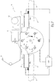
- the machine M shown in Figures 1 and 2 comprises a plate 1 rotating about a substantially horizontal axis X 1 , as represented by the arrow F 1 in Figure 2, and provided with six cylindrical mandrels with circular section 2 on which can be mounted packaging 3 partly cylindrical, in the example shown packaging intended to contain a shampoo.
- Each package 3 comprises an extruded tubular body of circular section 31 made of plastic, for example polypropylene, and a closure device 32 comprising a ring 33 screwed onto a one-piece thread with the body 31 and a stopper 34 articulated by means of a hinge 35 on the ring 33.
- the axis X 1 may be vertical or inclined.
- the mandrels 2 are not necessarily perpendicular to the plate 1.
- each package 3 is provided with a decoration 36 applied on its outer peripheral surface 31a and comprising an image and a text, in this case the letters "M”, on the one hand, and "RQUE", on the other hand, the word "BRAND" intended to be recognized by the user.
- machine M is used to form, by hot stamping, the letter "A” of the word "BRAND” to complete the decor 36, the letter A standing out, visually, from the rest of the word "BRAND” because of its method of marking.
- the marking is carried out by bringing a mandrel 2 on which is threaded a package 3 facing a heating punch 4 intended to press a metallized strip 5 against the surface 31a of the body 31.
- the tape 5 is stretched between a reel 51 and a reel 52 whose operation is known per se and which keep the ribbon 5 a voltage adapted to its function.
- the punch 4 is supported by an applicator 6 which makes it possible to move the punch 4 in a direction X parallel to the axis X 1 , in a direction Z which is generally vertical and in a direction Y perpendicular to the preceding ones.
- the punch 4 is not movable in the Z direction, whereas each mandrel 2 is vertically movable relative to the plate 1 by being appropriately controlled when it reaches the vicinity of the punch 4.
- the punch is not motorized vertically but only adjustable in height, while the mandrels are fixed relative to the plate.
- the mandrels 2 can take successively six positions P 1 , P 2 , P 3 , P 4 , P 5 and P 6 which are the following: the position P 1 corresponds to a loading position of a mandrel 2 with a package 3.
- the position P 2 corresponds to a locating position of one or more particular points of the package 3 mounted on the mandrel 2.
- the position P 3 corresponds to the marking position of the packing 3 in place on the mandrel 2.
- the position P 4 corresponds to an inspection position of the surface of the packaging and marking made in the P 3 position.
- the position P 5 is an unloading position in which the package 3 is removed from the mandrel 2.
- the position P 6 is a transit position.
- the mandrels 2 are shown equipped with packages 3 in each of the positions P 1 to P 5 .
- the mandrels 2 are visible, in transparency and in dotted lines, through the packages 3.
- the machine M is equipped with a linear marking camera 10 mounted on a support 11 fixed relative to the fixed frame B of the machine M, this frame defining the axis X 1 .
- the camera 10 may be of the type marketed by DALSA under the reference SPIDER 2 2048 points. It may also be of another type, in particular of the type provided for in FR-A-2,633,062 .
- the camera 10 is equipped with a lighting device 12 of its target area. The camera 10 makes it possible to inspect the outer surface of a package 3 mounted on a mandrel 2 in the position P 2 .
- the camera 10 is adapted to be able to aim the package 3 over its entire length, from the open end 31b of the body 31 to the cap 34, and over its entire circumference, insofar as the mandrel 2 can be rotated around its axis X 2 when in the position P 2 .
- the camera 10 is adapted to locate a particular point of the decoration 36 of each package 2 passing in the position P 2 .
- the camera 10 is able to locate a point A 1 corresponds to the intersection of the first two constituent lines of the letter M.
- the camera 10 being fixed relative to the frame B of the machine, it allows to identify the position of the decor 36 relative to the machine, taking into account the angular position of the mandrel 2 about its axis of rotation X 2 .
- the camera also makes it possible to locate the position of the point A 1 along the axis X 3 of the body 31 which is coincident with the axis X 2 when the package 3 is mounted on the mandrel 2.
- the machine M also comprises a linear control camera 20 mounted on a support 21 fixed relative to the frame B and provided with a lighting device 22.
- the camera 20 makes it possible to aim, for inspection, the external peripheral surface of a packaging 3 mounted on a mandrel 2 in the position P 4 after the marking has been carried out with the punch 4.
- the camera 20 makes it possible to locate one or more particular points of the decoration 36 and one or more particular points of the marking, in this case the letter "A".
- the machine M also comprises a control and control unit 100 to which signals S 10 and S 20 coming respectively from the cameras 10 and 20 are provided.
- the unit 100 is able to control the movements of the applicator 6 according to each of the X, Y and Z directions.
- the unit 100 is also capable of controlling the rotational movements of the plate 1 around its axis X 1 and each of the mandrels 2 around its axis X 2 .
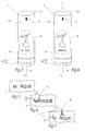
- the operation of the machine M is as follows: During normal operation, that is to say when the decoration 36 is known and when the marking to apply A is known, the camera 10 points on each body 31 of a package 3 passing in the position P 2 , the point A 1 . It transmits the corresponding information in the form of the signal S 10 to the unit 100 which drives the applicator 6 and the mandrel 2 correspondingly carrying this package to position the punch 4 so that the letter A formed by marking when hot is correctly positioned with respect to point A 1 . This makes it possible to go from the configuration of FIG. 3 to that of FIG.
- the location made by the camera 10 is particularly rapid, especially in comparison with measurements that could be performed with a dot matrix camera, so that the cycle time of a hot stamping operation is not increased by the use of this camera.
- the camera 20 makes it possible, in turn, to control the correct positioning of the letter A with respect to the decoration 36.
- the camera 20 is able to also locate the point A 1 and a remarkable point A 2 of the letter A, by example its top.
- the camera 20 thus makes it possible to determine the difference between the points A 1 and A 2 , both in the form of a gap e 1 taken parallel to the axis X 3 and in the form of a difference e 2 taken perpendicular to this axis.
- the output signal S 20 of the camera 20 enables the unit 100 to determine whether a package in the P 4 position meets or not a pre-established quality criterion for this type of packaging. If so, this packaging is used for the rest of the manufacturing process, otherwise it is considered a waste and is removed from the production line.
- the unit 100 is intended to control the relative positioning of a package 3 to be marked and the punch 4 as a function of the combination of the signal S 10 delivered by the camera 10 for this package and of the signal S 20 delivered by the camera 20 to a packaging marked previously in the machine M.
- the unit 100 takes into account a possible inaccuracy in the marking of an earlier packaging 3 to improve the accuracy of the marking of the package 3 being presented in front of the punch 4
- the signal S 20 used to correct the signal S 10 for marking a package 3 is that resulting from the inspection of a packaging of the same type marked immediately before.
- the particular point A 1 used by the registration camera 10 is not necessarily a point of the decoration 36. It may be a portion of a marker 37 affixed to the surface 31a near the end 31b. It may also be a part of the closure device 32, for example a particular point of the hinge 35. The particular point identified by the camera 10 may also be part of a weld when the body 31 is formed by welding in length of a material at least partly metal.
- the machine M can be adjusted particularly easily when a new manufacture has to be started, that is to say a new type of marking on packaging 3.
- a package 3 previously provided with a decor and marked correctly Such a reference package may have been manufactured with a previous batch of packages.
- This package 3 is mounted on a mandrel 2 in the position P 1 and "reads" the decoration 36 thanks to the camera 10 on the package 3 in place on the mandrel 2 brought to the position P 2 .
- This "reading” consists in locating the position of one or more particular points, such as the point A 1 , on the package 3 relative to the frame B of the machine, while the mandrel 2 rotates about its axis X 2 .
- the mandrel 2 equipped with the package 3 is then moved to the position P 4 without marking and the camera 20 is activated to "read" both the decoration 36 and the marking previously made, that is, to say the points A 1 and A 2 .
- the reference package is then unloaded when the mandrel 2 reaches the position P 5 .
- the same mandrel is then loaded with a package provided with a decoration 36 but not marked hot.
- the "scene" is read with the camera 10 and at least the position of a point A ' 1 corresponding to the point A 1 of the reference package is located.
- the corresponding signal S 10 is supplied to the unit 100.
- the mandrel is then conveyed to the position P 3 and the hot stamping is carried out by means of the punch 4, without particular adjustment of its position. We are talking about "random marking". A configuration of the type shown in FIG. 7 is obtained.
- the mandrel 2 is moved again to its position P 4 where both the decoration 36 and the marking "A" are read at the same time by identifying the point A ' 1 and a point A' 2 corresponding to the point A 2 .
- the camera 20 provides the unit 100 the corresponding result as the signal S 20 indicative of the axial deviation e '1 and of the gap perpendicular e' 2 between points A '1 and A' 2.
- the following packaging 3 and the punch 4 are automatically locked relative to each other, this thanks to the action of the linear positioning camera 10 and the unit 100.
- the camera 20 is then classically used to perform the quality control of the marking.
- the use of the two cameras 10 and 20 also makes it possible to perform statistical control of the average positioning errors of each mandrel. Indeed, after several tens of marking on a mandrel, for example 200 markings, it is possible to identify one or more repetitive positioning errors coming from the drive means of this mandrel, these errors possibly resulting from manufacturing tolerances of the drive means. or their wear. These errors can also result from inaccuracies during the production of the indexing device of the rotation of the plate 1 around its axis X 1 or errors in the manufacture of the mandrel itself, as far as its length and / or or its diameter. These errors are expressed in the form of a continuous error, or "statistical error", which can be taken into account, after analysis, to correct the signal S 10 . Specifically, the unit 100 takes account of this statistical error to interpret the signal S 10 and position the mandrel 2 by correcting this error.
- changes over time of this statistical positioning error can be used to detect the wear of the machine M, while being corrected at predetermined regular intervals, for example every 1000 marking operations.
- the invention has been represented with support members of packages 3 formed by these mandrels 2. It is also possible to use "tip-point” or "inter-point” type members in which the packagings are locked and rotated.
- the invention has been shown for a hot stamping machine. It also applies to other types of marking machines, for example label marking machines or direct marking machines, namely screen printing, pad printing, dry offset printing, letterpress printing, flexographic printing or jet printing. ink.
- the invention has been shown in its implementation for a cosmetic product package. It is applicable with all types of packaging and, in general, marking any object at least partially cylindrical.
Landscapes
- Engineering & Computer Science (AREA)
- Mechanical Engineering (AREA)
- Length Measuring Devices By Optical Means (AREA)
- Auxiliary Devices For And Details Of Packaging Control (AREA)
- Duplication Or Marking (AREA)
Priority Applications (1)
| Application Number | Priority Date | Filing Date | Title |
|---|---|---|---|
| PL06356117T PL1769916T3 (pl) | 2005-09-28 | 2006-09-27 | Urządzenie do znakowania przedmiotu cylindrycznego i sposoby realizowane takim urządzeniem |
Applications Claiming Priority (1)
| Application Number | Priority Date | Filing Date | Title |
|---|---|---|---|
| FR0509898A FR2891194B1 (fr) | 2005-09-28 | 2005-09-28 | Machine de marquage d'un objet cylindrique et procedes mis en oeuvre avec une telle machine |
Publications (3)
| Publication Number | Publication Date |
|---|---|
| EP1769916A2 true EP1769916A2 (de) | 2007-04-04 |
| EP1769916A3 EP1769916A3 (de) | 2007-08-29 |
| EP1769916B1 EP1769916B1 (de) | 2012-11-07 |
Family
ID=36643913
Family Applications (1)
| Application Number | Title | Priority Date | Filing Date |
|---|---|---|---|
| EP06356117A Not-in-force EP1769916B1 (de) | 2005-09-28 | 2006-09-27 | Vorrichtung und Verfahren zum Kennzeichnen von zylindrischen Objekten |
Country Status (4)
| Country | Link |
|---|---|
| EP (1) | EP1769916B1 (de) |
| ES (1) | ES2399283T3 (de) |
| FR (1) | FR2891194B1 (de) |
| PL (1) | PL1769916T3 (de) |
Cited By (12)
| Publication number | Priority date | Publication date | Assignee | Title |
|---|---|---|---|---|
| WO2009112160A1 (de) * | 2008-03-11 | 2009-09-17 | Polytype Sa | Modular aufgebaute lineardruckmaschine zum bedrucken von hohlkörpern mit unterschiedlichen druckverfahren |
| ITMO20090141A1 (it) * | 2009-05-26 | 2010-11-27 | Sacmi | Metodo e apparato di goffratura |
| ITRE20090058A1 (it) * | 2009-06-15 | 2010-12-16 | Omso Officina Macchine Per Stampa Su Oggetti S | Gruppo motorizzato porta mandrino per macchina da stampa |
| WO2010136496A3 (en) * | 2009-05-26 | 2011-01-27 | Sacmi Cooperativa Meccanici Imola Societa' Cooperativa | Embossing method and apparatus |
| FR2958627A1 (fr) * | 2010-04-12 | 2011-10-14 | Courval Verreries | Dispositif de marquage a chaud par tampographie d'articles en verre brut ou paracheve ou en matiere plastique. |
| CN101685488B (zh) * | 2008-09-22 | 2012-10-03 | 深圳市大族激光科技股份有限公司 | 激光打标机精度校正方法 |
| CN104097391A (zh) * | 2013-04-08 | 2014-10-15 | 安徽永昌金属制品有限公司 | 半自动印边机 |
| WO2016014959A1 (en) * | 2014-07-25 | 2016-01-28 | Illinois Tool Works Inc. | Decoration method, control system and decoration machine |
| WO2016113090A1 (de) * | 2015-01-12 | 2016-07-21 | Khs Gmbh | Erfassungseinheit sowie vorrichtung und verfahren zur bedruckung von behältern |
| WO2017032553A1 (de) * | 2015-08-21 | 2017-03-02 | Krones Ag | Direktdruckmaschine und verfahren zur bedruckung von behältern mit einem direktdruck |
| WO2018007038A1 (de) * | 2016-07-08 | 2018-01-11 | Krones Ag | Verfahren und vorrichtung zum mehrfarbigen tintenstrahldruck auf behälter |
| CN107818542A (zh) * | 2017-10-30 | 2018-03-20 | 凌云光技术集团有限责任公司 | 一种图像变形的修复方法及装置 |
Families Citing this family (3)
| Publication number | Priority date | Publication date | Assignee | Title |
|---|---|---|---|---|
| CN103847243B (zh) * | 2012-11-29 | 2015-10-14 | 大族激光科技产业集团股份有限公司 | 一种激光标记方法及装置 |
| ES2881688T3 (es) | 2013-10-09 | 2021-11-30 | Hinterkopf Gmbh | Instalación de inspección, procedimiento para la inspección óptica de una superficie de un objeto cilíndrico y equipo de impresión de chorro de tinta digital |
| US10682837B2 (en) | 2017-06-09 | 2020-06-16 | The Proctor & Gamble Company | Method and compositions for applying a material onto articles |
Family Cites Families (3)
| Publication number | Priority date | Publication date | Assignee | Title |
|---|---|---|---|---|
| IT1305329B1 (it) * | 1998-10-22 | 2001-05-04 | Omso Spa | Dispositivo automatico di rilevazione della qualita' di stampa suflaconi o bottiglie di forma qualunque |
| US6338263B1 (en) * | 1999-06-30 | 2002-01-15 | Toyo Seikan Kaisha, Ltd. | Method for manufacturing embossed can body, inspecting apparatus used for manufacturing embossed can body, and inspecting method used therefor |
| JP4885370B2 (ja) * | 2000-06-16 | 2012-02-29 | 株式会社ブリヂストン | 印刷装置、及び印刷方法 |
-
2005
- 2005-09-28 FR FR0509898A patent/FR2891194B1/fr not_active Expired - Fee Related
-
2006
- 2006-09-27 ES ES06356117T patent/ES2399283T3/es active Active
- 2006-09-27 PL PL06356117T patent/PL1769916T3/pl unknown
- 2006-09-27 EP EP06356117A patent/EP1769916B1/de not_active Not-in-force
Cited By (24)
| Publication number | Priority date | Publication date | Assignee | Title |
|---|---|---|---|---|
| WO2009112160A1 (de) * | 2008-03-11 | 2009-09-17 | Polytype Sa | Modular aufgebaute lineardruckmaschine zum bedrucken von hohlkörpern mit unterschiedlichen druckverfahren |
| CN101685488B (zh) * | 2008-09-22 | 2012-10-03 | 深圳市大族激光科技股份有限公司 | 激光打标机精度校正方法 |
| CN102574184A (zh) * | 2009-05-26 | 2012-07-11 | 萨克米伊莫拉机械合作社合作公司 | 压花方法和设备 |
| ITMO20090141A1 (it) * | 2009-05-26 | 2010-11-27 | Sacmi | Metodo e apparato di goffratura |
| US9296033B2 (en) | 2009-05-26 | 2016-03-29 | Sacmi Cooperativa Meccanici Imola Societa' Cooperativa | Embossing method and apparatus |
| CN102574184B (zh) * | 2009-05-26 | 2016-06-08 | 萨克米伊莫拉机械合作社合作公司 | 压花方法和设备 |
| US10022774B2 (en) | 2009-05-26 | 2018-07-17 | Sacmi Cooperativa Meccanici Imola Societa' Cooperativa | Embossing method and apparatus |
| WO2010136496A3 (en) * | 2009-05-26 | 2011-01-27 | Sacmi Cooperativa Meccanici Imola Societa' Cooperativa | Embossing method and apparatus |
| EP2263877A1 (de) * | 2009-06-15 | 2010-12-22 | Omso Decomac - Societa' a Responsabilita' Limitata | Motorisierte Dornhaltereinheit für eine Druckmaschine |
| US8110953B2 (en) | 2009-06-15 | 2012-02-07 | Omso Decomac-Societa' A Responsabilita' Limitata | Powered chuck-bearing group for a printing machine |
| CN101920594B (zh) * | 2009-06-15 | 2014-11-05 | 欧姆索德科马克有限责任公司 | 用于印刷机的动力夹具支承组件 |
| CN101920594A (zh) * | 2009-06-15 | 2010-12-22 | 欧姆索德科马克有限责任公司 | 用于印刷机的动力夹具支承组件 |
| ITRE20090058A1 (it) * | 2009-06-15 | 2010-12-16 | Omso Officina Macchine Per Stampa Su Oggetti S | Gruppo motorizzato porta mandrino per macchina da stampa |
| FR2958627A1 (fr) * | 2010-04-12 | 2011-10-14 | Courval Verreries | Dispositif de marquage a chaud par tampographie d'articles en verre brut ou paracheve ou en matiere plastique. |
| CN104097391A (zh) * | 2013-04-08 | 2014-10-15 | 安徽永昌金属制品有限公司 | 半自动印边机 |
| WO2016014959A1 (en) * | 2014-07-25 | 2016-01-28 | Illinois Tool Works Inc. | Decoration method, control system and decoration machine |
| FR3024075A1 (fr) * | 2014-07-25 | 2016-01-29 | Illinois Tool Works | Methode de decoration, systeme de controle et machine de decoration |
| US10479071B2 (en) | 2014-07-25 | 2019-11-19 | Illinois Tool Works Inc. | Decoration method, control system and decoration machine |
| WO2016113090A1 (de) * | 2015-01-12 | 2016-07-21 | Khs Gmbh | Erfassungseinheit sowie vorrichtung und verfahren zur bedruckung von behältern |
| US10144225B2 (en) | 2015-01-12 | 2018-12-04 | Khs Gmbh | Detection segment as well as device and method for printing containers |
| WO2017032553A1 (de) * | 2015-08-21 | 2017-03-02 | Krones Ag | Direktdruckmaschine und verfahren zur bedruckung von behältern mit einem direktdruck |
| US10279600B2 (en) | 2015-08-21 | 2019-05-07 | Krones Ag | Direct printing machine and method for printing containers using direct printing |
| WO2018007038A1 (de) * | 2016-07-08 | 2018-01-11 | Krones Ag | Verfahren und vorrichtung zum mehrfarbigen tintenstrahldruck auf behälter |
| CN107818542A (zh) * | 2017-10-30 | 2018-03-20 | 凌云光技术集团有限责任公司 | 一种图像变形的修复方法及装置 |
Also Published As
| Publication number | Publication date |
|---|---|
| ES2399283T3 (es) | 2013-03-27 |
| EP1769916B1 (de) | 2012-11-07 |
| EP1769916A3 (de) | 2007-08-29 |
| PL1769916T3 (pl) | 2013-04-30 |
| FR2891194A1 (fr) | 2007-03-30 |
| FR2891194B1 (fr) | 2007-11-30 |
Similar Documents
| Publication | Publication Date | Title |
|---|---|---|
| EP1769916B1 (de) | Vorrichtung und Verfahren zum Kennzeichnen von zylindrischen Objekten | |
| EP1132203B1 (de) | Verfahren und Vorrichtung zum automatischen Voreinstellen des Registers von Rotationsdruckmaschinen | |
| CN101506049A (zh) | 用于对容器沿周长贴标签的方法 | |
| EP2619012B1 (de) | Verfahren und anordnung zur registrierung von farben für eine druckmaschine | |
| EP1918100B1 (de) | Druckmaschine und Druckverfahren | |
| EP2236296B1 (de) | Vorrichtung und Verfahren zum Markieren oder Etikettieren | |
| WO2013098493A1 (fr) | Dispositif de mesure d'un profil interne ou externe d'un composant tubulaire | |
| FR2712231A1 (fr) | Maintien de la synchronisation des perforations dans une machine de fabrication de sacs en matière plastique ou équivalents. | |
| EP0824410A1 (de) | Gerät und verfahren zum anbringen von reifenwülsten | |
| EP3858750A1 (de) | Vorrichtung und verfahren zum kennzeichnen von behältern | |
| EP3017398A1 (de) | System zur inspektion eines mindestens durchscheinenden hohlen objekts mit mindestens einer markierung | |
| FR2763278A1 (fr) | Procede pour regler l'encrage pour l'impression continue dans une presse rotative a imprimer | |
| EP3265297A1 (de) | Verfahren zur inspektion von mit einer faserpositionierungsmaschine drapierten fasern | |
| EP4065949B1 (de) | System zur beurteilung des zustandes der oberfläche eines reifens | |
| EP2456613A1 (de) | Vorrichtung zur untersuchung der topografie einer substratoberfläche | |
| BE1028473A1 (fr) | Systeme et procede de commande pour le marquage en relief, de façon alignée, d'une feuille | |
| WO2019219273A1 (fr) | Procédé de traitement de surface d'une pièce et installation associée | |
| EP1809558B1 (de) | Verfahren und vorrichtung zur positionierung von streifen und rollen für deren verbindung mit einer abwickelmaschine | |
| EP4267946B1 (de) | Verfahren zur erkennung von defekten der horizontalen formdichtung für glasbehälter | |
| EP2444251B1 (de) | Tintenstrahldruckmaschine | |
| FR2867453A1 (fr) | Dispositif de pose sur un fardeau d'une poignee preparee | |
| EP1171371B1 (de) | Anlage für die behandlung von werkstücken wie etiketten oder bekleidungshülsen von flaschen | |
| EP1456038A1 (de) | Prüfverfahren für schreibgeräte | |
| FR2676129A1 (fr) | Procede destine a positionner un objet par rapport a un element a emplacement determine ou vice et versa et machine pour sa mise en óoeuvre. | |
| FR2846908A1 (fr) | Machine a etiqueter a transfert thermique avec controle de rembobinage et procede pour l'impression multiple d'etiquettes |
Legal Events
| Date | Code | Title | Description |
|---|---|---|---|
| PUAI | Public reference made under article 153(3) epc to a published international application that has entered the european phase |
Free format text: ORIGINAL CODE: 0009012 |
|
| AK | Designated contracting states |
Kind code of ref document: A2 Designated state(s): AT BE BG CH CY CZ DE DK EE ES FI FR GB GR HU IE IS IT LI LT LU LV MC NL PL PT RO SE SI SK TR |
|
| AX | Request for extension of the european patent |
Extension state: AL BA HR MK YU |
|
| PUAL | Search report despatched |
Free format text: ORIGINAL CODE: 0009013 |
|
| AK | Designated contracting states |
Kind code of ref document: A3 Designated state(s): AT BE BG CH CY CZ DE DK EE ES FI FR GB GR HU IE IS IT LI LT LU LV MC NL PL PT RO SE SI SK TR |
|
| AX | Request for extension of the european patent |
Extension state: AL BA HR MK YU |
|
| 17P | Request for examination filed |
Effective date: 20080218 |
|
| AKX | Designation fees paid |
Designated state(s): AT BE BG CH CY CZ DE DK EE ES FI FR GB GR HU IE IS IT LI LT LU LV MC NL PL PT RO SE SI SK TR |
|
| RAP1 | Party data changed (applicant data changed or rights of an application transferred) |
Owner name: ILLINOIS TOOL WORKS INC. Owner name: DECOSYSTEM S.R.L. |
|
| REG | Reference to a national code |
Ref country code: DE Ref legal event code: R079 Ref document number: 602006032890 Country of ref document: DE Free format text: PREVIOUS MAIN CLASS: B41F0017200000 Ipc: B41F0033000000 |
|
| GRAP | Despatch of communication of intention to grant a patent |
Free format text: ORIGINAL CODE: EPIDOSNIGR1 |
|
| RIC1 | Information provided on ipc code assigned before grant |
Ipc: B41F 17/18 20060101ALI20120611BHEP Ipc: G05D 3/20 20060101ALI20120611BHEP Ipc: B41F 15/08 20060101ALI20120611BHEP Ipc: B41F 17/00 20060101ALI20120611BHEP Ipc: B41F 33/00 20060101AFI20120611BHEP Ipc: B41F 17/28 20060101ALI20120611BHEP Ipc: B44B 5/00 20060101ALI20120611BHEP Ipc: B41F 19/06 20060101ALI20120611BHEP Ipc: B41F 17/08 20060101ALI20120611BHEP Ipc: G05D 3/12 20060101ALI20120611BHEP |
|
| GRAS | Grant fee paid |
Free format text: ORIGINAL CODE: EPIDOSNIGR3 |
|
| GRAA | (expected) grant |
Free format text: ORIGINAL CODE: 0009210 |
|
| AK | Designated contracting states |
Kind code of ref document: B1 Designated state(s): AT BE BG CH CY CZ DE DK EE ES FI FR GB GR HU IE IS IT LI LT LU LV MC NL PL PT RO SE SI SK TR |
|
| REG | Reference to a national code |
Ref country code: GB Ref legal event code: FG4D Free format text: NOT ENGLISH |
|
| REG | Reference to a national code |
Ref country code: CH Ref legal event code: EP Ref country code: AT Ref legal event code: REF Ref document number: 582827 Country of ref document: AT Kind code of ref document: T Effective date: 20121115 |
|
| REG | Reference to a national code |
Ref country code: IE Ref legal event code: FG4D Free format text: LANGUAGE OF EP DOCUMENT: FRENCH |
|
| REG | Reference to a national code |
Ref country code: DE Ref legal event code: R096 Ref document number: 602006032890 Country of ref document: DE Effective date: 20130103 |
|
| REG | Reference to a national code |
Ref country code: AT Ref legal event code: MK05 Ref document number: 582827 Country of ref document: AT Kind code of ref document: T Effective date: 20121107 |
|
| REG | Reference to a national code |
Ref country code: ES Ref legal event code: FG2A Ref document number: 2399283 Country of ref document: ES Kind code of ref document: T3 Effective date: 20130327 |
|
| REG | Reference to a national code |
Ref country code: NL Ref legal event code: VDEP Effective date: 20121107 |
|
| REG | Reference to a national code |
Ref country code: LT Ref legal event code: MG4D |
|
| PG25 | Lapsed in a contracting state [announced via postgrant information from national office to epo] |
Ref country code: FI Free format text: LAPSE BECAUSE OF FAILURE TO SUBMIT A TRANSLATION OF THE DESCRIPTION OR TO PAY THE FEE WITHIN THE PRESCRIBED TIME-LIMIT Effective date: 20121107 Ref country code: LT Free format text: LAPSE BECAUSE OF FAILURE TO SUBMIT A TRANSLATION OF THE DESCRIPTION OR TO PAY THE FEE WITHIN THE PRESCRIBED TIME-LIMIT Effective date: 20121107 Ref country code: IS Free format text: LAPSE BECAUSE OF FAILURE TO SUBMIT A TRANSLATION OF THE DESCRIPTION OR TO PAY THE FEE WITHIN THE PRESCRIBED TIME-LIMIT Effective date: 20130307 Ref country code: SE Free format text: LAPSE BECAUSE OF FAILURE TO SUBMIT A TRANSLATION OF THE DESCRIPTION OR TO PAY THE FEE WITHIN THE PRESCRIBED TIME-LIMIT Effective date: 20121107 Ref country code: NL Free format text: LAPSE BECAUSE OF FAILURE TO SUBMIT A TRANSLATION OF THE DESCRIPTION OR TO PAY THE FEE WITHIN THE PRESCRIBED TIME-LIMIT Effective date: 20121107 |
|
| REG | Reference to a national code |
Ref country code: PL Ref legal event code: T3 |
|
| PG25 | Lapsed in a contracting state [announced via postgrant information from national office to epo] |
Ref country code: LV Free format text: LAPSE BECAUSE OF FAILURE TO SUBMIT A TRANSLATION OF THE DESCRIPTION OR TO PAY THE FEE WITHIN THE PRESCRIBED TIME-LIMIT Effective date: 20121107 Ref country code: PT Free format text: LAPSE BECAUSE OF FAILURE TO SUBMIT A TRANSLATION OF THE DESCRIPTION OR TO PAY THE FEE WITHIN THE PRESCRIBED TIME-LIMIT Effective date: 20130307 Ref country code: SI Free format text: LAPSE BECAUSE OF FAILURE TO SUBMIT A TRANSLATION OF THE DESCRIPTION OR TO PAY THE FEE WITHIN THE PRESCRIBED TIME-LIMIT Effective date: 20121107 Ref country code: CY Free format text: LAPSE BECAUSE OF FAILURE TO SUBMIT A TRANSLATION OF THE DESCRIPTION OR TO PAY THE FEE WITHIN THE PRESCRIBED TIME-LIMIT Effective date: 20121107 Ref country code: GR Free format text: LAPSE BECAUSE OF FAILURE TO SUBMIT A TRANSLATION OF THE DESCRIPTION OR TO PAY THE FEE WITHIN THE PRESCRIBED TIME-LIMIT Effective date: 20130208 |
|
| PG25 | Lapsed in a contracting state [announced via postgrant information from national office to epo] |
Ref country code: AT Free format text: LAPSE BECAUSE OF FAILURE TO SUBMIT A TRANSLATION OF THE DESCRIPTION OR TO PAY THE FEE WITHIN THE PRESCRIBED TIME-LIMIT Effective date: 20121107 |
|
| PG25 | Lapsed in a contracting state [announced via postgrant information from national office to epo] |
Ref country code: BG Free format text: LAPSE BECAUSE OF FAILURE TO SUBMIT A TRANSLATION OF THE DESCRIPTION OR TO PAY THE FEE WITHIN THE PRESCRIBED TIME-LIMIT Effective date: 20130207 Ref country code: SK Free format text: LAPSE BECAUSE OF FAILURE TO SUBMIT A TRANSLATION OF THE DESCRIPTION OR TO PAY THE FEE WITHIN THE PRESCRIBED TIME-LIMIT Effective date: 20121107 Ref country code: DK Free format text: LAPSE BECAUSE OF FAILURE TO SUBMIT A TRANSLATION OF THE DESCRIPTION OR TO PAY THE FEE WITHIN THE PRESCRIBED TIME-LIMIT Effective date: 20121107 Ref country code: EE Free format text: LAPSE BECAUSE OF FAILURE TO SUBMIT A TRANSLATION OF THE DESCRIPTION OR TO PAY THE FEE WITHIN THE PRESCRIBED TIME-LIMIT Effective date: 20121107 Ref country code: CZ Free format text: LAPSE BECAUSE OF FAILURE TO SUBMIT A TRANSLATION OF THE DESCRIPTION OR TO PAY THE FEE WITHIN THE PRESCRIBED TIME-LIMIT Effective date: 20121107 |
|
| PG25 | Lapsed in a contracting state [announced via postgrant information from national office to epo] |
Ref country code: RO Free format text: LAPSE BECAUSE OF FAILURE TO SUBMIT A TRANSLATION OF THE DESCRIPTION OR TO PAY THE FEE WITHIN THE PRESCRIBED TIME-LIMIT Effective date: 20121107 |
|
| PLBE | No opposition filed within time limit |
Free format text: ORIGINAL CODE: 0009261 |
|
| STAA | Information on the status of an ep patent application or granted ep patent |
Free format text: STATUS: NO OPPOSITION FILED WITHIN TIME LIMIT |
|
| 26N | No opposition filed |
Effective date: 20130808 |
|
| REG | Reference to a national code |
Ref country code: DE Ref legal event code: R097 Ref document number: 602006032890 Country of ref document: DE Effective date: 20130808 |
|
| BERE | Be: lapsed |
Owner name: ILLINOIS TOOL WORKS INC. Effective date: 20130930 Owner name: DECOSYSTEM S.R.L. Effective date: 20130930 |
|
| PG25 | Lapsed in a contracting state [announced via postgrant information from national office to epo] |
Ref country code: MC Free format text: LAPSE BECAUSE OF FAILURE TO SUBMIT A TRANSLATION OF THE DESCRIPTION OR TO PAY THE FEE WITHIN THE PRESCRIBED TIME-LIMIT Effective date: 20121107 |
|
| REG | Reference to a national code |
Ref country code: CH Ref legal event code: PL |
|
| GBPC | Gb: european patent ceased through non-payment of renewal fee |
Effective date: 20130927 |
|
| REG | Reference to a national code |
Ref country code: IE Ref legal event code: MM4A |
|
| PG25 | Lapsed in a contracting state [announced via postgrant information from national office to epo] |
Ref country code: GB Free format text: LAPSE BECAUSE OF NON-PAYMENT OF DUE FEES Effective date: 20130927 Ref country code: LI Free format text: LAPSE BECAUSE OF NON-PAYMENT OF DUE FEES Effective date: 20130930 Ref country code: IE Free format text: LAPSE BECAUSE OF NON-PAYMENT OF DUE FEES Effective date: 20130927 Ref country code: BE Free format text: LAPSE BECAUSE OF NON-PAYMENT OF DUE FEES Effective date: 20130930 Ref country code: CH Free format text: LAPSE BECAUSE OF NON-PAYMENT OF DUE FEES Effective date: 20130930 |
|
| PG25 | Lapsed in a contracting state [announced via postgrant information from national office to epo] |
Ref country code: TR Free format text: LAPSE BECAUSE OF FAILURE TO SUBMIT A TRANSLATION OF THE DESCRIPTION OR TO PAY THE FEE WITHIN THE PRESCRIBED TIME-LIMIT Effective date: 20121107 |
|
| PG25 | Lapsed in a contracting state [announced via postgrant information from national office to epo] |
Ref country code: HU Free format text: LAPSE BECAUSE OF FAILURE TO SUBMIT A TRANSLATION OF THE DESCRIPTION OR TO PAY THE FEE WITHIN THE PRESCRIBED TIME-LIMIT; INVALID AB INITIO Effective date: 20060927 Ref country code: LU Free format text: LAPSE BECAUSE OF NON-PAYMENT OF DUE FEES Effective date: 20130927 |
|
| REG | Reference to a national code |
Ref country code: FR Ref legal event code: PLFP Year of fee payment: 10 |
|
| REG | Reference to a national code |
Ref country code: FR Ref legal event code: PLFP Year of fee payment: 11 |
|
| REG | Reference to a national code |
Ref country code: FR Ref legal event code: PLFP Year of fee payment: 12 |
|
| REG | Reference to a national code |
Ref country code: FR Ref legal event code: PLFP Year of fee payment: 13 |
|
| PGFP | Annual fee paid to national office [announced via postgrant information from national office to epo] |
Ref country code: IT Payment date: 20230921 Year of fee payment: 18 |
|
| PGFP | Annual fee paid to national office [announced via postgrant information from national office to epo] |
Ref country code: PL Payment date: 20230901 Year of fee payment: 18 Ref country code: FR Payment date: 20230925 Year of fee payment: 18 Ref country code: DE Payment date: 20230927 Year of fee payment: 18 |
|
| PGFP | Annual fee paid to national office [announced via postgrant information from national office to epo] |
Ref country code: ES Payment date: 20231002 Year of fee payment: 18 |
|
| REG | Reference to a national code |
Ref country code: DE Ref legal event code: R119 Ref document number: 602006032890 Country of ref document: DE |
|
| PG25 | Lapsed in a contracting state [announced via postgrant information from national office to epo] |
Ref country code: DE Free format text: LAPSE BECAUSE OF NON-PAYMENT OF DUE FEES Effective date: 20250401 |
|
| PG25 | Lapsed in a contracting state [announced via postgrant information from national office to epo] |
Ref country code: IT Free format text: LAPSE BECAUSE OF NON-PAYMENT OF DUE FEES Effective date: 20240927 |
|
| PG25 | Lapsed in a contracting state [announced via postgrant information from national office to epo] |
Ref country code: FR Free format text: LAPSE BECAUSE OF NON-PAYMENT OF DUE FEES Effective date: 20240930 |
|
| REG | Reference to a national code |
Ref country code: ES Ref legal event code: FD2A Effective date: 20251031 |
|
| PG25 | Lapsed in a contracting state [announced via postgrant information from national office to epo] |
Ref country code: ES Free format text: LAPSE BECAUSE OF NON-PAYMENT OF DUE FEES Effective date: 20240928 |
|
| PG25 | Lapsed in a contracting state [announced via postgrant information from national office to epo] |
Ref country code: PL Free format text: LAPSE BECAUSE OF NON-PAYMENT OF DUE FEES Effective date: 20240927 |