EP1809558B1 - Verfahren und vorrichtung zur positionierung von streifen und rollen für deren verbindung mit einer abwickelmaschine - Google Patents
Verfahren und vorrichtung zur positionierung von streifen und rollen für deren verbindung mit einer abwickelmaschine Download PDFInfo
- Publication number
- EP1809558B1 EP1809558B1 EP05814793A EP05814793A EP1809558B1 EP 1809558 B1 EP1809558 B1 EP 1809558B1 EP 05814793 A EP05814793 A EP 05814793A EP 05814793 A EP05814793 A EP 05814793A EP 1809558 B1 EP1809558 B1 EP 1809558B1
- Authority
- EP
- European Patent Office
- Prior art keywords
- strip
- machine
- emitter
- roll
- new
- Prior art date
- Legal status (The legal status is an assumption and is not a legal conclusion. Google has not performed a legal analysis and makes no representation as to the accuracy of the status listed.)
- Expired - Lifetime
Links
Images

Classifications
-
- B—PERFORMING OPERATIONS; TRANSPORTING
- B65—CONVEYING; PACKING; STORING; HANDLING THIN OR FILAMENTARY MATERIAL
- B65H—HANDLING THIN OR FILAMENTARY MATERIAL, e.g. SHEETS, WEBS, CABLES
- B65H19/00—Changing the web roll
- B65H19/10—Changing the web roll in unwinding mechanisms or in connection with unwinding operations
- B65H19/18—Attaching, e.g. pasting, the replacement web to the expiring web
- B65H19/1842—Attaching, e.g. pasting, the replacement web to the expiring web standing splicing, i.e. the expiring web being stationary during splicing contact
- B65H19/1852—Attaching, e.g. pasting, the replacement web to the expiring web standing splicing, i.e. the expiring web being stationary during splicing contact taking place at a distance from the replacement roll
-
- B—PERFORMING OPERATIONS; TRANSPORTING
- B65—CONVEYING; PACKING; STORING; HANDLING THIN OR FILAMENTARY MATERIAL
- B65H—HANDLING THIN OR FILAMENTARY MATERIAL, e.g. SHEETS, WEBS, CABLES
- B65H19/00—Changing the web roll
- B65H19/10—Changing the web roll in unwinding mechanisms or in connection with unwinding operations
- B65H19/12—Lifting, transporting, or inserting the web roll; Removing empty core
- B65H19/126—Lifting, transporting, or inserting the web roll; Removing empty core with both-ends supporting arrangements
-
- B—PERFORMING OPERATIONS; TRANSPORTING
- B65—CONVEYING; PACKING; STORING; HANDLING THIN OR FILAMENTARY MATERIAL
- B65H—HANDLING THIN OR FILAMENTARY MATERIAL, e.g. SHEETS, WEBS, CABLES
- B65H23/00—Registering, tensioning, smoothing or guiding webs
- B65H23/02—Registering, tensioning, smoothing or guiding webs transversely
- B65H23/0204—Sensing transverse register of web
- B65H23/0216—Sensing transverse register of web with an element utilising photoelectric effect
-
- B—PERFORMING OPERATIONS; TRANSPORTING
- B65—CONVEYING; PACKING; STORING; HANDLING THIN OR FILAMENTARY MATERIAL
- B65H—HANDLING THIN OR FILAMENTARY MATERIAL, e.g. SHEETS, WEBS, CABLES
- B65H2557/00—Means for control not provided for in groups B65H2551/00 - B65H2555/00
- B65H2557/50—Use of particular electromagnetic waves, e.g. light, radiowaves or microwaves
- B65H2557/51—Laser
Definitions
- the present invention relates to the field of machines for continuously unwinding and rolling web materials, in particular machines for unwinding rolls of paper or cardboard, for the purpose of feeding a machine downstream and for the purpose of a method of positioning strips and coils for connection to a machine to unwind.
- the invention also relates to a device for implementing this method.
- a coil being scrolled is placed on one of the two pins of a machine to unroll.
- a new coil is placed on hold on the second unwinding pin of said unwinding machine.
- the beginning of the strip of this new coil must be positioned so that it is correctly aligned both laterally and angularly with the finishing band.
- the new coils and strips are pre-positioned by the operator using graduated scales arranged on the spindle carrying the spool and on the preparation area of the beginning of the tape waiting for connection.
- the operator will slide the spool onto the spindle until the end of the mandrel, made of cardboard or other material, of the spool is placed in close proximity.
- a reference 600 mm corresponding to the graduated scale of the spindle bearing said coil so that the -flanc heart of the coil is placed as accurately as possible in front of the reference 600 mm corresponding, that is to say say either aligned with this mark.
- the operator will unroll a sufficient length of the new band that will have in front of the reference 600 mm of the ruler graduated from the holding zone of the beginning of this new band. In this way, an apparently correct alignment is achieved between the new reel and the unrolling machine and the new web will be able to scroll in the unwinding machine without risk of slanting.
- the new coil has a defect in shape, for example when the flank at the outer diameter of the coil is not plumb with the flank at the inside diameter, then the beginning of the new strip may be placed, in the preparation zone of the beginning of the strip, at an angle to the longitudinal axis of the machine. This results in malfunctions, including longitudinal folds that can cause breakage of the tape running or damage the main part of the production line.
- these sensors do not emit a visible light beam to materialize a position, that is to say, allowing an operator to perfectly locate a vertical plane, in which the edge of a coil must be positioned, without intervention of specific means of enslavement.
- US-A-5,133,511 describes a positioning method of measuring the position of a band by means of a a position sensor and a CCD camera which, as a function of the number and the position of the activated pixels of the sensor, informs a control and control member on the position of the strip.
- This method uses a light source which is a lamp illuminating the area filmed by the CCD camera and is not adapted to the materialization of a position by issuing a line of light.
- US-A-4,131,206 also discloses a tape positioning method, wherein the tape is moved laterally until a light flux of a light beam emitted by a light source and picked up by a receiver is interrupted.
- This method uses a means of the photoelectric barrier type, the source of which is not intended to materialize a position on the tape, but to illuminate a receiver informing a controller on the position of the tape.
- the present invention aims to overcome the disadvantages of known methods and devices by proposing a method of positioning strips and coils for connection to a machine to unwind and a device for implementing this method to ensure a perfect alignment between the finishing band and new band and a strip unwinding without longitudinal folds by performing a set of operations entirely under the control of an operator verifying the position, without implementation of complementary electronic control means and / or complex and expensive computer
- the method according to the invention is characterized in that it consists in materializing, at the outer diameter of a coil, by means of a light beam emitter of visible light by an operator and without setting implementation of an active receiver, the position at which the side of said coil is to be positioned relative to the longitudinal axis of the unwinding machine.
- the invention also relates to a device for implementing this method, which is characterized in that it consists essentially of at least one light beam emitter in the form of at least one linear beam or from less a light plane of visible light by an operator, said transmitter cooperating with a passive indexing means, without implementation of an active receiver.
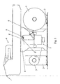
- FIG. 1 of the accompanying drawings shows a machine for unwinding rolls of paper or cardboard for feeding a downstream machine such as a printing machine or the like, this machine consisting essentially of a support frame 1 means 2 coil carrier 3, movable transversely to the longitudinal axis of the machine, and optionally a tape accumulation device 4 and a set 5 for preparing a new band to connect and junction of this tape to a finishing tape.
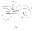
- a device which consists essentially of at least one emitter 6 of light beam in the form of at least one linear beam or at least one plane light of light visible by an operator, said transmitter cooperating with a passive indexing means 7, 71 ( figures 2 and 4 ) provided on the assembly 5 for preparing a new band to connect and joining this band to a finishing band, without implementation of an active receiver.
- the positioning of strips and coils for connection consists of loading a spool 3 on the free spindle of a means 2 for a spool holder until a corresponding mark 9 is reached ( figures 2 and 4 ), then possibly laterally position the transmitter 6 relative to the longitudinal axis of the machine, in cooperation with the passive indexing means 7, 71, without implementation of an active receiver, on a corresponding corresponding reference on said passive indexing means 7, 71, in order to align the light beam which is projected by the transmitter 6 with respect to this passive indexing means 7, 71, to then transmit, by means of said transmitter 6, a beam light of light visible by an operator on the new spool 3 in place on the corresponding spindle of the means 2 spool holder, so as to allow the operator to move the means 2 spool holder laterally to bring the flank of the outer diameter of the coil 3 in coincidence with the light beam projected by the transmitter 6 and to align and prepare the beginning of new band.
- the positioning of the transmitter 6 is not performed systematically, such positioning is not necessary if the new coil has the same width as the finishing coil.
- the passive indexing means 7 is constituted by a graduated ruler mounted on the assembly 5 for preparing a new strip to be connected and joining this strip to a finishing strip.
- the passive indexing means 71 in the form of a mounting bracket of the transmitter 6, this support being provided with positioning marks 71 'corresponding to marks 700' of a strip 700 of checking the position of the new strip of a set 5 for preparing a new band to be connected and joining this band to a finishing band.
- This support forming the passive indexing means 71 can be made in the form of a guide provided with mark positioning markers or in the form of a guide provided with a digital display means of the position.
- the loading of the reel 3, for example with a width of 600 mm on the spindle of the means 2 reel holder, can be performed at the corresponding reference 600 mm provided as reference 9 and the positioning of the transmitter 6 will then be performed on the corresponding reference 600 mm provided on the graduated scale forming the passive indexing means 7 ( figure 2 ) and mounted on the assembly 5 for preparing a new band to connect and joining this band to a finishing band and said new band is aligned laterally in coincidence with said light beam visible light emitted by the transmitter 6.
- the new band is perfectly aligned with respect to the axis of travel of the machine and with the finishing band, so that no longitudinal fold can be created after connection.
- the emitter 6 can emit a linear beam or a light plane, or two intersecting light planes arranged for example at 90 degrees to one another, so that the resulting trace visible on the periphery of the coil 3 is respectively : a point, a line or a cross.
- the transmitter 6 may be provided with a prism or dividing mirrors of its light beam. As a result, a part of the latter may be directed on the periphery of the spool 3 and the other part may be directed to the holding area of the beginning of the strip in the assembly 5 for the preparation of a new connecting strip and joining this strip to a finishing strip, passing on a graduated ruler 7 ( figure 2 ) located in this holding zone.
- the device may comprise two transmitters, one directed towards the coil 3 and the other towards the holding zone of the assembly 5 for preparing a new band to be connected and to join this band to a band, these transmitters being integral with each other.
- the emitter 6 is preferably selected from the family of laser diodes, but any other strongly convergent light source may be used.
- the unwinding machine described in connection with the present invention is symmetrical to allow the new spool 3 to be located to the right or to the left of the vertical center axis of the machine. Indeed, when the reel 3 being rewound is placed to the right with respect to the median vertical axis of the machine, then a new reel 3 is placed to the left of this axis and the end of the strip of this new reel is prepared and placed in the holding zone to the left of this axis, in the assembly 5 for preparing a new band to be connected and joining this band to a finishing band. Then, when the unwinding reel 3 arrives at the end of the tape, the finishing tape is connected with the new tape.
- the accumulator or tape accumulation device 4 placed above the unwinding machine and whose role is to accumulate a sufficient length of tape, before making the connection.
- the speed of the unwinding machine is temporarily increased with respect to the speed of the downstream machine, so that the excess length produced can be accumulated between the cylinders of the accumulator.
- the connection operation which requires the stopping of the tape running at the connection area.
- the downstream machine is fed by the extra length of band available in the accumulator 4, which empties progressively.
- the new coil placed to the left of the middle axis is unrolled instead of the old one ( figure 1 ).
- the old coil 3 on the right which is empty or almost empty, is evacuated and replaced by a new coil 3 located this time on the right.
- the operator of the machine will proceed to the correct positioning of the new band of this coil 3 by means of the positioning device according to the invention, simply by a visual control of the position of the visible light beam emitted by the transmitter 6, in combination with the medium passive indexing 7 or 71, without implementation of a verification means such as a sensor.
- the operations will follow one another in this way by alternately using the right and left positioning devices of the machine.
- This device makes it possible to ensure perfect angular positioning between the moving web and the web in preparation. However, there may still be a slight lateral misalignment, due to a lateral defect on the reel being scrolled.
- a lateral guide device 8 ( figure 3 ).
- This lateral guiding device 8 is disposed downstream of the connection zone of the assembly 5 for preparing a new band to be connected and joining this band to a finishing band and slaving the lateral position of the band being formed. scrolling with respect to the longitudinal axis of the machine.
- the lateral guiding device 8 is advantageously in the form of a means for controlling the lateral position of the strip with respect to the longitudinal axis of the machine informing a central unit of the position side of the strip and which consists of a set of two optical cells 8 ', 8 "arranged next to each other near an edge of the strip and slightly spaced laterally with respect to the longitudinal axis
- This device 8 may be arranged on the left side of the strip, when an observer observes the machine to unroll from the front, the downstream machine being arranged in extension of the strip.
- the correct position of the band is obtained when only one of the cells 8 ', 8 "is activated
- the band is moving laterally to the left, seen in the direction of travel, and it is then necessary to move the coil 3 correspondingly running by means of its trolley 2 reel holder to the right, in order to refocus the band scrolling.
- the displacement of the carriages 2 reel carriers is carried transversely to the longitudinal axis of the machine to unwind by means of electric motors, in a manner known per se and is not described in detail.
- the reel carriage is moved in such a way that the moving web is automatically re-centered.
- the lateral guiding device 8 By combining the lateral guiding device 8 with the emitter 6, it is possible to maintain, on the one hand, an optimal lateral position of the moving web and, on the other hand, to ensure that the position of the web the new reel 3 will be in alignment with the old tape and will run without creating longitudinal folds.
Landscapes
- Replacement Of Web Rolls (AREA)
- Manufacturing Of Electrical Connectors (AREA)
Claims (16)
- Verfahren zur Positionierung von Bändern und Rollen für deren Verbindung an einer Abwickelmaschine, dadurch gekennzeichnet, dass es darin besteht, auf dem Niveau des Außendurchmessers einer Rolle (3) mittels wenigstens eines Emitters (6) für Leuchtstrahlenbündel aus für einen Operator sichtbarem Licht und ohne die Verwendung eines aktiven Empfängers die Position zu markieren, an der die Flanke der besagten Rolle (3) bezogen auf die Längsachse der Abwickelmaschine positioniert werden soll.
- Verfahren gemäß Anspruch 1, dadurch gekennzeichnet, dass es in der Realisierung des Ladens einer Rolle (3) auf der freien Welle eines Rollenhaltemittels (2) bis zum Erreichen einer korrespondierenden Markierung (9), in der gegebenenfalls anschließenden lateralen Positionierung des Emitters bezogen auf die Längsachse der Maschine unter Mitwirkung von einem passiven Indexierungsmittel (7, 71), das an einer Einrichtung (5) für die Vorbereitung eines neuen zu verbindenden Bandes und für das Verbinden dieses Bandes mit einem endenden Band vorgesehen ist, ohne die Verwendung eines aktiven Empfängers an einer korrespondierenden Markierung, die an besagtem passiven Indexierungsmittel (7, 71) vorgesehen ist, um das Leuchtstrahlenbündel, das von dem Emitter ausgestrahlt wird, bezogen auf dieses passive Indexierungsmittel (7, 71) auszurichten, und dem ausschließenden Emittieren eines Leuchtstrahlenbündels aus für einen Operator sichtbarem Licht mittels besagtem Emitter (6) auf die neue Rolle (3) an der Stelle der Welle, die mit dem Rollenhaltemittel (2) korrespondiert, in der Weise, dass es dem Operator das seitliche Verschieben des Rollenhaltemittels (2) erlaubt, um die diametral äußere Flanke der Rolle (3) in Übereinstimmung mit dem Leuchtstrahlenbündel, das von der Leuchtquelle (6) ausgestrahlt wird, zu bringen und den Anfang des neuen Bandes auszurichten und vorzubereiten.
- Verfahren gemäß Anspruch 2, dadurch gekennzeichnet, dass das Leuchtstrahlenbündel, das von dem Emitter (6) ausgestrahlt wird, die Form eines linearen Strahlenbündels oder einer Leuchtebene oder zwei sich schneidender Leuchtebenen besitzt.
- Verfahren gemäß Anspruch 2, dadurch gekennzeichnet, dass ein Teil des Leuchtstrahlenbündels auf den Außenbereich der Rolle (3) gerichtet ist und der andere Teil auf die Zone der Einrichtung (5) für die Vorbereitung eines neuen zu verbindenden Bandes für das Verbinden dieses Bandes mit einem endenden Band, die den Anfang des Bandes erhält, gerichtet ist und über ein skaliertes Lineal (7 oder 700) läuft, das in dieser Zone, die das Band erhält, angeordnet ist und das passive Indexierungsmittel (7) bildet, oder über ein Lineal (700) zur Überprüfung der Position des neuen Bandes.
- Vorrichtung für die Benutzung des Verfahrens gemäß einem der Ansprüche 1 bis 4 in einer Abwickelmaschine für Rollen mit Papier oder Karton bezogen auf die Zuführung für eine Maschine wie eine Druckmaschine oder dergleichen, die in Richtung stromabwärts platziert ist, wobei diese Maschine im Wesentlichen aus einem Haltegestell (1) für das Haltemittel (2) für Rollen (3), die transversal beweglich auf der Längsachse der Maschine sind, und eventuell einer Bandsammelvorrichtung (4) und einer Einrichtung (5) für das Vorbereiten eines neuen zu verbindenden Bandes und für das Verbinden dieses Bandes mit einem endenden Band besteht, dadurch gekennzeichnet, dass sie im Wesentlichen aus wenigstens einem Emitter (6) für Leuchtstrahlenbündel in der Form von wenigstens einem linearen Strahlenbündel oder wenigstens einer Leuchtebene mit für einen Operator sichtbarem Licht gebildet ist, wobei besagter wenigstens eine Emitter (6) mit einem passiven Indexierungsmittel (7, 71) kooperiert, ohne dass ein aktiver Empfänger verwendet wird.
- Vorrichtung gemäß Anspruch 5, dadurch gekennzeichnet, dass das passive Indexierungsmittel (7) aus einem skalierten Lineal gebildet ist, das auf der Einrichtung (5) für das Vorbereiten eines neuen zu verbindenden Bandes für das Verbinden dieses Bandes mit einem endenden Band montiert ist.
- Vorrichtung gemäß Anspruch 5, dadurch gekennzeichnet, dass das passive Indexierungsmittel (71) in der Form einer Montagehalterung für den Emitter (6) ausgebildet ist, wobei diese Montagehalterung mit Positionsmarkierungen (71') versehen ist, die mit Markierungen (700') eines Lineals (700) korrespondieren, um die Position des neuen Bandes in der Einrichtung (5) für das Vorbereiten eines neuen zu verbindenden Bandes und für das Verbinden dieses Bandes mit einem endenden Band zu verifizieren.
- Vorrichtung gemäß Anspruch 7, dadurch gekennzeichnet, dass die Halterung, die das passive Indexierungsmittel (71) bildet, in der Form einer Führung, die mit Markierungen zur Positionierung mittels Markierungen oder auch in der Form einer Führung, die mit einem numerischen Anzeigemittel für die Position versehen ist, realisiert ist.
- Vorrichtung gemäß Anspruch 5, dadurch gekennzeichnet, dass der Emitter (6) mit einem Prisma oder Spiegeln für die Aufspaltung seines Lichtstrahlenbündels versehen ist.
- Vorrichtung gemäß Anspruch 5, dadurch gekennzeichnet, dass sie zwei Emitter umfasst, von denen der eine auf die Rolle (3) gerichtet ist und der andere auf die Zone der Einrichtung (5) für die Vorbereitung eines neuen zu verbindenden Bandes, die das Band erhält, gerichtet ist, um dieses Band mit einem endenden Band zu verbinden, wobei diese Emitter integral miteinander ausgeführt sind.
- Vorrichtung gemäß Anspruch 5, dadurch gekennzeichnet, dass der Emitter ein einzelner ist und ein Strahlenbündel mit einem Öffnungswinkel hat, so dass es eine Leuchtebene bildet, die gleichzeitig die Rolle (3) und die Vorbereitungszone der Einrichtung (5) für die Vorbereitung eines neuen zu verbindenden Bandes und für das Verbinden dieses Bandes mit einem endenden Band erfasst.
- Vorrichtung gemäß einem der Ansprüche 5 bis 11, dadurch gekennzeichnet, dass der Emitter (6) aus der Familie der Laserdioden gewählt ist.
- Vorrichtung gemäß einem der Ansprüche 5 bis 11, dadurch gekennzeichnet, dass der Emitter (6) von einer Art mit einem stark konvergierenden Strahlenbündel ist.
- Vorrichtung gemäß einem der Ansprüche 5 bis 11, dadurch gekennzeichnet, dass sie von einer seitlichen Führungsvorrichtung (8) ergänzt ist.
- Vorrichtung gemäß Anspruch 14, dadurch gekennzeichnet, dass die seitliche Führungsvorrichtung (8) in der Richtung stromabwärts von der Verbindungszone der Einrichtung (5) für die Vorbereitung eines neuen zu verbindenden Bandes und für das Verbinden dieses Bandes mit einem endenden Band vorgesehen ist und die seitliche Position des Bandes im Laufe der Abwicklung bezogen auf die Längsachse der Maschine steuert.
- Vorrichtung gemäß einem der Ansprüche 14 und 15, dadurch gekennzeichnet, dass die seitliche Führungsvorrichtung (8) in der Form eines Steuerungsmittels für die laterale Position des Bandes bezogen auf die Längsachse der Maschine ausgebildet ist, welches eine Zentraleinheit über die laterale Position des Bandes informiert, und dass sie aus einer Anordnung von zwei optischen Zellen (8', 8'') gebildet wird, die nebeneinander in der Nähe eines Randes des Bandes und bezogen auf die Längsachse der Maschine geringfügig lateral versetzt angeordnet sind.
Applications Claiming Priority (2)
| Application Number | Priority Date | Filing Date | Title |
|---|---|---|---|
| FR0411993A FR2877655B1 (fr) | 2004-11-10 | 2004-11-10 | Procede et dispositif de positionnement de bandes et de bobines en vue du raccordement sur une machine a derouler |
| PCT/FR2005/002753 WO2006051194A1 (fr) | 2004-11-10 | 2005-11-04 | Procede et dispositif de positionnement de bandes et de bobines en vue du raccordement sur une machine a derouler |
Publications (3)
| Publication Number | Publication Date |
|---|---|
| EP1809558A1 EP1809558A1 (de) | 2007-07-25 |
| EP1809558B1 true EP1809558B1 (de) | 2008-04-23 |
| EP1809558B8 EP1809558B8 (de) | 2008-07-16 |
Family
ID=34951237
Family Applications (1)
| Application Number | Title | Priority Date | Filing Date |
|---|---|---|---|
| EP05814793A Expired - Lifetime EP1809558B8 (de) | 2004-11-10 | 2005-11-04 | Verfahren und vorrichtung zur positionierung von streifen und rollen für deren verbindung mit einer abwickelmaschine |
Country Status (7)
| Country | Link |
|---|---|
| US (1) | US20090057476A1 (de) |
| EP (1) | EP1809558B8 (de) |
| AT (1) | ATE393111T1 (de) |
| DE (1) | DE602005006306T2 (de) |
| ES (1) | ES2306253T3 (de) |
| FR (1) | FR2877655B1 (de) |
| WO (1) | WO2006051194A1 (de) |
Families Citing this family (5)
| Publication number | Priority date | Publication date | Assignee | Title |
|---|---|---|---|---|
| KR102474343B1 (ko) * | 2016-12-14 | 2022-12-05 | 현대자동차 주식회사 | 롤투롤 피딩 설비의 오토 스플라이싱 장치 |
| CN106516827B (zh) * | 2016-12-19 | 2017-10-20 | 安徽鲲鹏装备模具制造有限公司 | 一种皮料开卷上料系统 |
| CN107098194A (zh) * | 2017-06-26 | 2017-08-29 | 上海精涂新材料技术有限公司 | 收卷胶带与弧面对准的装置 |
| EP4086211B1 (de) * | 2021-05-04 | 2023-08-23 | Comexi Group Industries, S.A.U | Filmaufwickler-maschine mit einem fehlerausrichtungsdetektor und ein fehlausrichtungs-erkennungsverfahren in einer filmaufwickler-maschine |
| DE102024130047A1 (de) * | 2024-10-16 | 2026-04-16 | Fischer Tiretech Germany Gmbh | Einrichtung zur Bereitstellung eines Materialbands, insbesondere eines Cordbands |
Family Cites Families (13)
| Publication number | Priority date | Publication date | Assignee | Title |
|---|---|---|---|---|
| US2373644A (en) * | 1941-12-08 | 1945-04-17 | Emil E Belch | Wallpaper cutting, pasting, and folding machine |
| US3570735A (en) * | 1968-11-18 | 1971-03-16 | Gpe Controls Inc | Method and apparatus of guiding moving webs |
| US4021031A (en) * | 1975-12-08 | 1977-05-03 | Butler Automatic, Inc. | Web alignment system |
| JPS53115308A (en) * | 1977-03-04 | 1978-10-07 | Tokyo Kikai Seisakushiyo Kk | Device for automatically supplying rolled paper in rotary press |
| JPS5931244A (ja) * | 1982-08-09 | 1984-02-20 | Dainippon Printing Co Ltd | 給紙装置の紙継ぎ方法 |
| DE3931852A1 (de) * | 1989-09-23 | 1991-04-04 | Erhardt & Leimer Gmbh | Rollenwechsler |
| JPH04341444A (ja) * | 1991-05-20 | 1992-11-27 | Rockwell Graphic Syst Japan:Kk | 巻取紙の自動装着装置 |
| US5221058A (en) * | 1991-08-01 | 1993-06-22 | Packaging Coordinators, Inc. | Registration control for continuously moving laminated package apparatus |
| US5643395A (en) * | 1992-09-01 | 1997-07-01 | Cms Gilbreth Packaging Systems, Inc. | Automatic splicing apparatus |
| DE59706549D1 (de) * | 1996-12-21 | 2002-04-11 | Koenig & Bauer Ag | Verfahren zum Lageerfassen und Positionieren einer Vorratsbahnrolle |
| US6069748A (en) * | 1998-10-20 | 2000-05-30 | Eastman Kodak Company | Laser line generator system |
| JP3041619B1 (ja) * | 1999-04-23 | 2000-05-15 | 株式会社東京機械製作所 | 給紙部における巻取紙の装着装置 |
| US6595460B1 (en) * | 2000-08-22 | 2003-07-22 | Innovative Solutions, Inc. | Web material alignment apparatus and method |
-
2004
- 2004-11-10 FR FR0411993A patent/FR2877655B1/fr not_active Expired - Fee Related
-
2005
- 2005-11-04 AT AT05814793T patent/ATE393111T1/de not_active IP Right Cessation
- 2005-11-04 US US11/667,353 patent/US20090057476A1/en not_active Abandoned
- 2005-11-04 ES ES05814793T patent/ES2306253T3/es not_active Expired - Lifetime
- 2005-11-04 DE DE602005006306T patent/DE602005006306T2/de not_active Expired - Lifetime
- 2005-11-04 WO PCT/FR2005/002753 patent/WO2006051194A1/fr not_active Ceased
- 2005-11-04 EP EP05814793A patent/EP1809558B8/de not_active Expired - Lifetime
Also Published As
| Publication number | Publication date |
|---|---|
| FR2877655B1 (fr) | 2007-03-30 |
| DE602005006306T2 (de) | 2009-05-14 |
| EP1809558B8 (de) | 2008-07-16 |
| ATE393111T1 (de) | 2008-05-15 |
| FR2877655A1 (fr) | 2006-05-12 |
| DE602005006306D1 (de) | 2008-06-05 |
| WO2006051194A1 (fr) | 2006-05-18 |
| EP1809558A1 (de) | 2007-07-25 |
| US20090057476A1 (en) | 2009-03-05 |
| ES2306253T3 (es) | 2008-11-01 |
Similar Documents
| Publication | Publication Date | Title |
|---|---|---|
| EP0245187B1 (de) | Einrichtung zum automatischen Aufladen von Rollen auf Abwicklungsmaschinen | |
| FR2492350A1 (fr) | Dispositif pour bobinage de feuilles | |
| FR2514100A1 (fr) | Procede de montage automatique d'un rouleau d'une feuille continue sur un support | |
| FR2676427A1 (fr) | Procede et dispositif de bobinage d'une bande de film. | |
| EP0301989B1 (de) | Maschine zum Abwickeln von Bahnen mit Gestellen für Wickelrollen | |
| FR2531941A1 (fr) | Machine pour la decoupe de pieces dans une matiere en bande | |
| EP1809558B1 (de) | Verfahren und vorrichtung zur positionierung von streifen und rollen für deren verbindung mit einer abwickelmaschine | |
| FR2660641A1 (fr) | Procede de changement de bande sur une machine de fabrication. | |
| FR2472044A1 (fr) | Procede et dispositif pour inserer localement un ruban elastique dans un drap housse adaptable autour d'un matelas | |
| EP0318427A1 (de) | Verfahren und Maschine zum Aneinanderfügen von Papierstreifen für die ununterbrochene Zufuhr an eine Maschine, insbesondere für die Herstellung von Zigaretten | |
| FR3033140A1 (fr) | Procede de depose d'une bande de matiere et dispositif pour sa mise en oeuvre | |
| EP2516146B1 (de) | Verfahren und vorrichtung zur messung des lagenwinkels vor einem schneidvorgang | |
| EP1577219B1 (de) | Vorrichtung zum Anbringen eines Tragegriffs | |
| FR2724227A1 (fr) | Procede et dispositif pour preparer des masselottes d'equilibrage adhesives pour des jantes de vehicules automobiles. | |
| FR2725154A1 (fr) | Procede et dispositif d'application d'une bande de roulement premoulee et prevulcanisee sur une carcasse de pneumatique | |
| WO2010015782A2 (fr) | Dispositif de fourniture et installation de depose d'une bande de gomme | |
| EP0349438A1 (de) | Verfahren und Vorrichtung für die Identifizierung eines Schreibgerätes | |
| FR2807395A1 (fr) | Derouleur/enrouleur pour bande-support d'etiquettes adhesives ou objets similaires | |
| BE1005324A3 (fr) | Appareil d'acheminement de la feuille en rouleau d'un traceur et procede de reglage du parcours d'acheminement de la feuille en rouleau. | |
| EP1209108B1 (de) | Verfahren zum Verbinden zweier Rollen in einer Hüllmaschine zum Aufbringen von Hüllen auf Flaschen und Hüllmaschine zur Ausführung des Verfahrens | |
| WO2002047984A1 (fr) | Poste de pose automatique d'etiquettes | |
| EP3727825B1 (de) | Verfahren zum aufbringen einer verstärkungslage auf eine gross dimensionierte trommel | |
| FR3138453A1 (fr) | Dispositif et méthode d’application d’un marquage sur une surface | |
| EP3892575A1 (de) | Vorrichtung zum zuführen von folie zu einer schrumpffolienverpackungsmaschine mit mindestens zwei abrollern, die jeweils mit einem abdeckgehäuse versehen sind | |
| FR2880329A1 (fr) | Procede et dispositif de raccordement de deux gaines tubulaires aplaties dans une machine de pose de manchons sur des objets en defilement |
Legal Events
| Date | Code | Title | Description |
|---|---|---|---|
| PUAI | Public reference made under article 153(3) epc to a published international application that has entered the european phase |
Free format text: ORIGINAL CODE: 0009012 |
|
| 17P | Request for examination filed |
Effective date: 20070502 |
|
| AK | Designated contracting states |
Kind code of ref document: A1 Designated state(s): AT BE BG CH CY CZ DE DK EE ES FI FR GB GR HU IE IS IT LI LT LU LV MC NL PL PT RO SE SI SK TR |
|
| GRAP | Despatch of communication of intention to grant a patent |
Free format text: ORIGINAL CODE: EPIDOSNIGR1 |
|
| DAX | Request for extension of the european patent (deleted) | ||
| GRAS | Grant fee paid |
Free format text: ORIGINAL CODE: EPIDOSNIGR3 |
|
| GRAA | (expected) grant |
Free format text: ORIGINAL CODE: 0009210 |
|
| AK | Designated contracting states |
Kind code of ref document: B1 Designated state(s): AT BE BG CH CY CZ DE DK EE ES FI FR GB GR HU IE IS IT LI LT LU LV MC NL PL PT RO SE SI SK TR |
|
| REG | Reference to a national code |
Ref country code: GB Ref legal event code: FG4D Free format text: NOT ENGLISH |
|
| REG | Reference to a national code |
Ref country code: CH Ref legal event code: EP |
|
| RAP2 | Party data changed (patent owner data changed or rights of a patent transferred) |
Owner name: MONOMATIC (SOCIETE PAR ACTIONS SIMPLIFIEE) |
|
| REF | Corresponds to: |
Ref document number: 602005006306 Country of ref document: DE Date of ref document: 20080605 Kind code of ref document: P |
|
| REG | Reference to a national code |
Ref country code: IE Ref legal event code: FG4D |
|
| REG | Reference to a national code |
Ref country code: CH Ref legal event code: NV Representative=s name: SCHNEIDER FELDMANN AG PATENT- UND MARKENANWAELTE |
|
| NLT2 | Nl: modifications (of names), taken from the european patent patent bulletin |
Owner name: MONOMATIC (SOCIETE PAR ACTIONS SIMPLIFIEE) Effective date: 20080604 |
|
| REG | Reference to a national code |
Ref country code: SE Ref legal event code: TRGR |
|
| PG25 | Lapsed in a contracting state [announced via postgrant information from national office to epo] |
Ref country code: SI Free format text: LAPSE BECAUSE OF FAILURE TO SUBMIT A TRANSLATION OF THE DESCRIPTION OR TO PAY THE FEE WITHIN THE PRESCRIBED TIME-LIMIT Effective date: 20080423 |
|
| PG25 | Lapsed in a contracting state [announced via postgrant information from national office to epo] |
Ref country code: BG Free format text: LAPSE BECAUSE OF FAILURE TO SUBMIT A TRANSLATION OF THE DESCRIPTION OR TO PAY THE FEE WITHIN THE PRESCRIBED TIME-LIMIT Effective date: 20080723 |
|
| REG | Reference to a national code |
Ref country code: ES Ref legal event code: FG2A Ref document number: 2306253 Country of ref document: ES Kind code of ref document: T3 |
|
| PG25 | Lapsed in a contracting state [announced via postgrant information from national office to epo] |
Ref country code: PL Free format text: LAPSE BECAUSE OF FAILURE TO SUBMIT A TRANSLATION OF THE DESCRIPTION OR TO PAY THE FEE WITHIN THE PRESCRIBED TIME-LIMIT Effective date: 20080423 Ref country code: LV Free format text: LAPSE BECAUSE OF FAILURE TO SUBMIT A TRANSLATION OF THE DESCRIPTION OR TO PAY THE FEE WITHIN THE PRESCRIBED TIME-LIMIT Effective date: 20080423 Ref country code: AT Free format text: LAPSE BECAUSE OF FAILURE TO SUBMIT A TRANSLATION OF THE DESCRIPTION OR TO PAY THE FEE WITHIN THE PRESCRIBED TIME-LIMIT Effective date: 20080423 |
|
| REG | Reference to a national code |
Ref country code: IE Ref legal event code: FD4D |
|
| PG25 | Lapsed in a contracting state [announced via postgrant information from national office to epo] |
Ref country code: IS Free format text: LAPSE BECAUSE OF FAILURE TO SUBMIT A TRANSLATION OF THE DESCRIPTION OR TO PAY THE FEE WITHIN THE PRESCRIBED TIME-LIMIT Effective date: 20080823 |
|
| PG25 | Lapsed in a contracting state [announced via postgrant information from national office to epo] |
Ref country code: IE Free format text: LAPSE BECAUSE OF FAILURE TO SUBMIT A TRANSLATION OF THE DESCRIPTION OR TO PAY THE FEE WITHIN THE PRESCRIBED TIME-LIMIT Effective date: 20080423 Ref country code: CZ Free format text: LAPSE BECAUSE OF FAILURE TO SUBMIT A TRANSLATION OF THE DESCRIPTION OR TO PAY THE FEE WITHIN THE PRESCRIBED TIME-LIMIT Effective date: 20080423 Ref country code: DK Free format text: LAPSE BECAUSE OF FAILURE TO SUBMIT A TRANSLATION OF THE DESCRIPTION OR TO PAY THE FEE WITHIN THE PRESCRIBED TIME-LIMIT Effective date: 20080423 Ref country code: LT Free format text: LAPSE BECAUSE OF FAILURE TO SUBMIT A TRANSLATION OF THE DESCRIPTION OR TO PAY THE FEE WITHIN THE PRESCRIBED TIME-LIMIT Effective date: 20080423 |
|
| PG25 | Lapsed in a contracting state [announced via postgrant information from national office to epo] |
Ref country code: RO Free format text: LAPSE BECAUSE OF FAILURE TO SUBMIT A TRANSLATION OF THE DESCRIPTION OR TO PAY THE FEE WITHIN THE PRESCRIBED TIME-LIMIT Effective date: 20080423 Ref country code: SK Free format text: LAPSE BECAUSE OF FAILURE TO SUBMIT A TRANSLATION OF THE DESCRIPTION OR TO PAY THE FEE WITHIN THE PRESCRIBED TIME-LIMIT Effective date: 20080423 |
|
| PLBE | No opposition filed within time limit |
Free format text: ORIGINAL CODE: 0009261 |
|
| STAA | Information on the status of an ep patent application or granted ep patent |
Free format text: STATUS: NO OPPOSITION FILED WITHIN TIME LIMIT |
|
| 26N | No opposition filed |
Effective date: 20090126 |
|
| PG25 | Lapsed in a contracting state [announced via postgrant information from national office to epo] |
Ref country code: EE Free format text: LAPSE BECAUSE OF FAILURE TO SUBMIT A TRANSLATION OF THE DESCRIPTION OR TO PAY THE FEE WITHIN THE PRESCRIBED TIME-LIMIT Effective date: 20080423 |
|
| PG25 | Lapsed in a contracting state [announced via postgrant information from national office to epo] |
Ref country code: CY Free format text: LAPSE BECAUSE OF FAILURE TO SUBMIT A TRANSLATION OF THE DESCRIPTION OR TO PAY THE FEE WITHIN THE PRESCRIBED TIME-LIMIT Effective date: 20080423 Ref country code: HU Free format text: LAPSE BECAUSE OF FAILURE TO SUBMIT A TRANSLATION OF THE DESCRIPTION OR TO PAY THE FEE WITHIN THE PRESCRIBED TIME-LIMIT Effective date: 20081024 |
|
| PG25 | Lapsed in a contracting state [announced via postgrant information from national office to epo] |
Ref country code: TR Free format text: LAPSE BECAUSE OF FAILURE TO SUBMIT A TRANSLATION OF THE DESCRIPTION OR TO PAY THE FEE WITHIN THE PRESCRIBED TIME-LIMIT Effective date: 20080423 |
|
| PG25 | Lapsed in a contracting state [announced via postgrant information from national office to epo] |
Ref country code: GR Free format text: LAPSE BECAUSE OF FAILURE TO SUBMIT A TRANSLATION OF THE DESCRIPTION OR TO PAY THE FEE WITHIN THE PRESCRIBED TIME-LIMIT Effective date: 20080724 |
|
| PG25 | Lapsed in a contracting state [announced via postgrant information from national office to epo] |
Ref country code: PT Free format text: LAPSE BECAUSE OF FAILURE TO SUBMIT A TRANSLATION OF THE DESCRIPTION OR TO PAY THE FEE WITHIN THE PRESCRIBED TIME-LIMIT Effective date: 20080423 |
|
| REG | Reference to a national code |
Ref country code: FR Ref legal event code: PLFP Year of fee payment: 12 |
|
| REG | Reference to a national code |
Ref country code: FR Ref legal event code: PLFP Year of fee payment: 13 |
|
| REG | Reference to a national code |
Ref country code: FR Ref legal event code: PLFP Year of fee payment: 14 |
|
| REG | Reference to a national code |
Ref country code: CH Ref legal event code: PFA Owner name: MONOMATIC (SOCIETE PAR ACTIONS SIMPLIFIEE), FR Free format text: FORMER OWNER: MONOMATIC (SOCIETE PAR ACTIONS SIMPLIFIEE), FR |
|
| P01 | Opt-out of the competence of the unified patent court (upc) registered |
Effective date: 20230620 |
|
| PGFP | Annual fee paid to national office [announced via postgrant information from national office to epo] |
Ref country code: NL Payment date: 20241129 Year of fee payment: 20 |
|
| PGFP | Annual fee paid to national office [announced via postgrant information from national office to epo] |
Ref country code: DE Payment date: 20241129 Year of fee payment: 20 |
|
| PGFP | Annual fee paid to national office [announced via postgrant information from national office to epo] |
Ref country code: MC Payment date: 20241126 Year of fee payment: 20 |
|
| PGFP | Annual fee paid to national office [announced via postgrant information from national office to epo] |
Ref country code: BE Payment date: 20241129 Year of fee payment: 20 Ref country code: LU Payment date: 20241129 Year of fee payment: 20 Ref country code: FI Payment date: 20241125 Year of fee payment: 20 |
|
| PGFP | Annual fee paid to national office [announced via postgrant information from national office to epo] |
Ref country code: GB Payment date: 20241129 Year of fee payment: 20 |
|
| PGFP | Annual fee paid to national office [announced via postgrant information from national office to epo] |
Ref country code: FR Payment date: 20241129 Year of fee payment: 20 |
|
| PGFP | Annual fee paid to national office [announced via postgrant information from national office to epo] |
Ref country code: IT Payment date: 20241127 Year of fee payment: 20 Ref country code: ES Payment date: 20241230 Year of fee payment: 20 |
|
| PGFP | Annual fee paid to national office [announced via postgrant information from national office to epo] |
Ref country code: SE Payment date: 20241129 Year of fee payment: 20 |
|
| PGFP | Annual fee paid to national office [announced via postgrant information from national office to epo] |
Ref country code: CH Payment date: 20241205 Year of fee payment: 20 |
|
| REG | Reference to a national code |
Ref country code: CH Ref legal event code: H14 Free format text: ST27 STATUS EVENT CODE: U-0-0-H10-H14 (AS PROVIDED BY THE NATIONAL OFFICE) Effective date: 20251104 Ref country code: DE Ref legal event code: R071 Ref document number: 602005006306 Country of ref document: DE |
|
| REG | Reference to a national code |
Ref country code: NL Ref legal event code: MK Effective date: 20251103 |
|
| REG | Reference to a national code |
Ref country code: ES Ref legal event code: FD2A Effective date: 20251126 Ref country code: GB Ref legal event code: PE20 Expiry date: 20251103 |
|
| REG | Reference to a national code |
Ref country code: BE Ref legal event code: MK Effective date: 20251104 |
|
| PG25 | Lapsed in a contracting state [announced via postgrant information from national office to epo] |
Ref country code: ES Free format text: LAPSE BECAUSE OF EXPIRATION OF PROTECTION Effective date: 20251105 |