EP1769989B1 - Ventil zum hydraulischen Bremsen einer Arbeitsmaschine oder dergleichen - Google Patents
Ventil zum hydraulischen Bremsen einer Arbeitsmaschine oder dergleichen Download PDFInfo
- Publication number
- EP1769989B1 EP1769989B1 EP20060120866 EP06120866A EP1769989B1 EP 1769989 B1 EP1769989 B1 EP 1769989B1 EP 20060120866 EP20060120866 EP 20060120866 EP 06120866 A EP06120866 A EP 06120866A EP 1769989 B1 EP1769989 B1 EP 1769989B1
- Authority
- EP
- European Patent Office
- Prior art keywords
- slider
- valve according
- seat
- port
- elastic means
- Prior art date
- Legal status (The legal status is an assumption and is not a legal conclusion. Google has not performed a legal analysis and makes no representation as to the accuracy of the status listed.)
- Active
Links
Images

Classifications
-
- E—FIXED CONSTRUCTIONS
- E02—HYDRAULIC ENGINEERING; FOUNDATIONS; SOIL SHIFTING
- E02F—DREDGING; SOIL-SHIFTING
- E02F9/00—Component parts of dredgers or soil-shifting machines, not restricted to one of the kinds covered by groups E02F3/00 - E02F7/00
- E02F9/20—Drives; Control devices
- E02F9/2004—Control mechanisms, e.g. control levers
-
- B—PERFORMING OPERATIONS; TRANSPORTING
- B60—VEHICLES IN GENERAL
- B60T—VEHICLE BRAKE CONTROL SYSTEMS OR PARTS THEREOF; BRAKE CONTROL SYSTEMS OR PARTS THEREOF, IN GENERAL; ARRANGEMENT OF BRAKING ELEMENTS ON VEHICLES IN GENERAL; PORTABLE DEVICES FOR PREVENTING UNWANTED MOVEMENT OF VEHICLES; VEHICLE MODIFICATIONS TO FACILITATE COOLING OF BRAKES
- B60T15/00—Construction arrangement, or operation of valves incorporated in power brake systems and not covered by groups B60T11/00 or B60T13/00
- B60T15/02—Application and release valves
- B60T15/04—Driver's valves
- B60T15/041—Driver's valves controlling auxiliary pressure brakes, e.g. parking or emergency brakes
-
- B—PERFORMING OPERATIONS; TRANSPORTING
- B60—VEHICLES IN GENERAL
- B60T—VEHICLE BRAKE CONTROL SYSTEMS OR PARTS THEREOF; BRAKE CONTROL SYSTEMS OR PARTS THEREOF, IN GENERAL; ARRANGEMENT OF BRAKING ELEMENTS ON VEHICLES IN GENERAL; PORTABLE DEVICES FOR PREVENTING UNWANTED MOVEMENT OF VEHICLES; VEHICLE MODIFICATIONS TO FACILITATE COOLING OF BRAKES
- B60T7/00—Brake-action initiating means
- B60T7/02—Brake-action initiating means for personal initiation
- B60T7/08—Brake-action initiating means for personal initiation hand actuated
-
- F—MECHANICAL ENGINEERING; LIGHTING; HEATING; WEAPONS; BLASTING
- F16—ENGINEERING ELEMENTS AND UNITS; GENERAL MEASURES FOR PRODUCING AND MAINTAINING EFFECTIVE FUNCTIONING OF MACHINES OR INSTALLATIONS; THERMAL INSULATION IN GENERAL
- F16K—VALVES; TAPS; COCKS; ACTUATING-FLOATS; DEVICES FOR VENTING OR AERATING
- F16K31/00—Actuating devices; Operating means; Releasing devices
- F16K31/44—Mechanical actuating means
- F16K31/52—Mechanical actuating means with crank, eccentric, or cam
- F16K31/523—Mechanical actuating means with crank, eccentric, or cam comprising a sliding valve
-
- G—PHYSICS
- G05—CONTROLLING; REGULATING
- G05G—CONTROL DEVICES OR SYSTEMS INSOFAR AS CHARACTERISED BY MECHANICAL FEATURES ONLY
- G05G1/00—Controlling members, e.g. knobs or handles; Assemblies or arrangements thereof; Indicating position of controlling members
- G05G1/04—Controlling members for hand actuation by pivoting movement, e.g. levers
-
- G—PHYSICS
- G05—CONTROLLING; REGULATING
- G05G—CONTROL DEVICES OR SYSTEMS INSOFAR AS CHARACTERISED BY MECHANICAL FEATURES ONLY
- G05G5/00—Means for preventing, limiting or returning the movements of parts of a control mechanism, e.g. locking controlling member
- G05G5/06—Means for preventing, limiting or returning the movements of parts of a control mechanism, e.g. locking controlling member for holding members in one or a limited number of definite positions only
- G05G5/08—Interlocking of members, e.g. locking member in a particular position before or during the movement of another member
-
- Y—GENERAL TAGGING OF NEW TECHNOLOGICAL DEVELOPMENTS; GENERAL TAGGING OF CROSS-SECTIONAL TECHNOLOGIES SPANNING OVER SEVERAL SECTIONS OF THE IPC; TECHNICAL SUBJECTS COVERED BY FORMER USPC CROSS-REFERENCE ART COLLECTIONS [XRACs] AND DIGESTS
- Y10—TECHNICAL SUBJECTS COVERED BY FORMER USPC
- Y10T—TECHNICAL SUBJECTS COVERED BY FORMER US CLASSIFICATION
- Y10T137/00—Fluid handling
- Y10T137/8593—Systems
- Y10T137/86493—Multi-way valve unit
- Y10T137/86574—Supply and exhaust
- Y10T137/8667—Reciprocating valve
- Y10T137/86694—Piston valve
- Y10T137/86702—With internal flow passage
Definitions
- the present invention relates to a valve for hydraulic braking of work machines or the like.
- the brakes are kept released by means of a hydraulic system provided with jacks which contrast the elastic force of the springs.
- This modulation is usually performed by using suitable manually actuated hydraulic valves, wherein the term “manual” references any intervention performed directly by the operator for example by means of a lever, pedal or the like.
- valves are constituted usually by an outer casing provided with ports for connection respectively to a pressurized oil supply pump, to an oil discharge tank and to the brake locking jacks.
- a longitudinal seat is formed within the casing and a contoured slider slides therein, allowing to connect to each other the connecting ports, particularly to send pressurized fluid to the jacks and release the brakes, or to discharge the contents into the discharge tank and allow the springs of the brakes to slow/block the work machine.
- the slider is moved by means of the actuation lever or pedal in contrast with two springs arranged inside the casing; in detail, a first spring acts directly on the slider and control the pressure of the oil fed to the jacks, while a second spring is designed to load the first spring with a force which is sufficient to deliver the brake release pressure.
- valves When the brakes are engaged and the work machine is stationary, these known types of valve are provided with a bolt which is actuated by a contrast spring and locks rigidly the lever or pedal, prevents accidental release of the brakes, and avoids the onset of potentially dangerous situations.
- Document FR-2 857 705 discloses a fluid distribution device allowing reduction of the pressure load in the outlet tube according to the preamble of claim 1.
- the aim of the present invention is to eliminate the drawbacks noted above of the background art, by providing a valve for the hydraulic braking of work machines or the like which allows to engage and release the brakes in a particularly simple, convenient manner and most of all with limited effort on the part of the operator.
- Another object of the present invention is to make the braking system particularly reactive to commands and allow easy modulation of the braking action.
- Another object of the present invention is to provide a system for locking the valve in safe conditions which is very simple both structurally and functionally.
- Another object of the present invention is to provide a valve having a structure which is simple, relatively easy to provide in practice, safe in use, effective in operation, and has a relatively low cost.
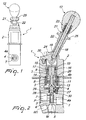
- the reference numeral 1 generally designates a valve for the hydraulic braking of work machines or the like.
- the valve 1 comprises an outer casing 2, in which there is a longitudinal sliding seat 3 for a slider 4, a first port P for connecting the seat 3 to a pumping assembly for feeding pressurized fluid, a second port T for connecting the seat 3 to a fluid recovery and discharge tank, a third port M for connecting the seat 3 to the jacks of the braking system of a work machine or the like, and a fourth port M 1 , which is connected to the third port M and is designed for the coupling of a measuring means for measuring the pressure of the jacks, such as a pressure-controlled switch or the like.
- the slider 4 is constituted by a flow control element 4a and by a pusher spool 4b, both of which are elongated longitudinally with respect to the seat 3 and are kept in mutual contact.
- the flow control element 4a is merely a contoured portion which is suitable to allow/prevent the passage of the fluid through the connecting ports P, T and M and on which there is a reaction surface which substantially faces the third port M and is sensitive to the pressure of the fluid at the jacks.
- said contoured portion is provided with an end 5 which faces axially the third port M and laterally faces the second port T; the movement of the slider 4 in a first direction away from the third port M in practice is adapted to connect the second port T and the third port M and to discharge the fluid from the jacks to the discharge tank (which corresponds to an increase in the braking capacity of the brakes).
- the contoured portion 4a comprises a longitudinal cavity 6, which is open at the end 5 that faces the third port M, and a plurality of transverse openings 7 for connecting the longitudinal cavity 6 to the first port P; the movement of the slider 4 in a second direction for sliding toward the third port M in practice is adapted to connect the first port P and the third port M and send the fluid to the jacks (which corresponds to a reduction in the braking capacity of the brakes).
- the reaction surface of the flow control element 4a is formed in practice by the edge of the end 5 and by the bottom of the longitudinal cavity 6.
- the spool 4b is constituted by a pivot which has a circular cross-section and a variable thickness and is associated with sliding actuation means for actuating the sliding of the slider 4 in the seat 3 in contrast with the pressurized fluid that strikes or anyway contacts said reaction surface.
- Said actuation means comprise first elastic means 8, which are interposed between the casing 2 and the slider 4 and are adapted to contrast the thrust of the fluid that strikes the reaction surface, second elastic means 9, which can be interposed between a first abutment element 10 associated with the slider 4 and a second abutment element 11 arranged within the casing 2 and are adapted to contrast the thrust of the first elastic means 8, and manual actuation means 12 for manually actuating the loading/unloading of the second elastic means 9.
- the first elastic means 8 are constituted by a first preloaded helical compression spring, which is wound around the spool 4b and has it ends in abutment between an abutment plate 13, in contact with the end of the spool 4b that is adjacent to the flow control element 4a, and a supporting surface 14, which is formed within the casing 2 and is directed toward the flow control element 4a.
- the second elastic means 9 are constituted by a second preloaded helical compression spring, which is also wound around the spool 4b.
- the first abutment element 10 on which the second helical spring 9 can engage is constituted by a shoulder which is provided at the end of the spool 4b that lies opposite the contoured portion 4a; the second abutment element 11 is constituted instead by a supporting washer, which is arranged around a substantially central portion of the slider 4 and can slide longitudinally with respect to the seat 3.
- the manual actuation means 12 are constituted by a mechanism for moving the washer 11 between a spaced configuration and a closer configuration with respect to the shoulder 10.
- cup-shaped elements 15 which can slide along the seat 3, surrounds the end part of the spool 4b and is provided with a closed end, which is arranged proximate to the shoulder 10, and an open end, which is associated with the washer 11.
- the second helical spring 9 is arranged inside the cup-shaped element 15 and rests directly at one end on the washer 11 and is adjacent, at the opposite end, to a retention ring 16 which surrounds the spool 4b.
- Said retention ring can slide with respect to the cup-shaped element 15 and during use it can rest against the shoulder 10 of the spool 4b or against an abutment recess 17 provided within said element.
- the elastic force of the second helical spring 9 is applied to the slider 4 and is subtracted from the elastic force produced by the first helical spring 8 in order to contrast the pressure of the fluid that acts against the flow control element 4a; when instead the retention ring 16 is adjacent to the abutment recess 17, the second helical spring 9 has no effect on the slider 4 and remains preloaded between said retention ring and the washer 11.
- an actuator device of the lever type is associated with the cup-shaped element 15 and allows to slide said cup-shaped element along the seat 3; however, alternative embodiments are also possible in which said device can be of the pedal-operated type.
- said lever device has a lever 18, which is associated rotatably with a body 19 for coupling to the cup-shaped element 15 and is provided with an eccentric portion 20, which can engage in abutment against the casing 2 and is adapted to convert the rotary motion of the lever 18 into the sliding motion of the cup-shaped element 15 along the seat 3.
- Removable locking means 21 for the removable locking of the lever 18 in a stroke limit configuration that corresponds to the full engagement of the brakes of the work machine are provided on the lever 18.
- Said removable locking means comprise a tubular body 22, which can slide coaxially around the lever 18, third elastic means 23, which are interposed between the lever 18 and the tubular body 22 and are adapted to press said tubular body against the coupling body 19, and a slot 24, which is formed on the coupling body 19 and in which the tubular body 22 can engage in the stroke limit configuration.
- the tubular body 22 slides on the spherical head of the coupling body 19 until, at the stroke limit, it is pushed into the slot 24 by virtue of the action of the third elastic means 23; to release the lever 18 from the stroke limit configuration, the tubular body 22 is provided externally with a grip wing 25, which allows to disengage it from the slot 24.
- the washer 11 is adapted to be placed in contact against an abutment surface 26 of the spool 4b of the slider 4 and move the flow control element 4a away from the third port M, so as to leave open the passage between the second and third ports T and M and discharge completely the pressure of the fluid at the jacks.
- the valve 1 according to the invention is completed by virtue of stabilizer means for stabilizing the sliding of the slider 4 in the seat 3.
- said stabilizer means comprise a disk 27, which is fitted coaxially around the flow control element 4a and is kept rigidly, jointly coupled thereto by way of a conical helical spring 28, which pushes said disk against a locking ring 29.
- the disk 27 slides snugly within a portion of the seat 3 and forms, together with the internal walls of the casing 2, an isolated chamber 30; the movement of the disk 27 by the flow control element 4a pumps, by seepage, the fluid in input and in output from the chamber 30 and therefore dampens the vibrations of the slider 4.
- This configuration corresponds to the condition in which the jacks are pressurized and the brakes are released: in practice, the pressure of the fluid at the jacks is determined by the extent of the preloading of the first helical spring 8.
- the cup-shaped element 15 slides within the seat 3 until it places the shoulder 10 in contact with the retention ring 16 and thus applies the preloading of the second helical spring 9 to the slider 4.
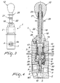
- the thrust of the first helical spring 8 is reduced by the value equal to the preloading of the second helical spring 9, the flow control element 4a performs a translational motion, opening the passage between the second port T and the third port M and discharging most of the pressure of the fluid to the jacks, until a new balanced configuration ( Figure 2 ) is achieved for the slider 4.
- the washer 11 engages the abutment surface 26 and lifts the slider 4, keeping stably open the passage between the second port T and the third port M and permanently discharging the pressure of the jacks.
- the present invention allows to achieve a rapid pressure drop in the initial steps of the discharge of the jacks, leaving most of the stroke of the lever for more simple brake control.
Landscapes
- Engineering & Computer Science (AREA)
- General Engineering & Computer Science (AREA)
- Mechanical Engineering (AREA)
- General Physics & Mathematics (AREA)
- Automation & Control Theory (AREA)
- Transportation (AREA)
- Physics & Mathematics (AREA)
- Mining & Mineral Resources (AREA)
- Civil Engineering (AREA)
- Structural Engineering (AREA)
- Mechanically-Actuated Valves (AREA)
- Valve Device For Special Equipments (AREA)
- Lift Valve (AREA)
- Braking Arrangements (AREA)
- Braking Systems And Boosters (AREA)
Claims (20)
- Ein Ventil für eine Hydraulikbremse einer Arbeitsmaschine oder ähnlichem, umfassend:- eine äußere Hülse (2), welche mit einer Längsaufnahme (3) ausgestattet ist und mindestens eine erste Ventilöffnung (P) zur Verbindung der Aufnahme (3) mit einer Pumpenanordnung zur Zuführung von unter Druck stehenden Flüssigkeiten, mindestens eine zweite Ventilöffnung (T) zur Verbindung der Aufnahme (3) mit einem Fluid-Ab- und -Rücklauftank und mindestens eine dritte Ventilöffnung (M) zur Verbindung der Aufnahme (3) mit einem Bremssystem einer Arbeitsmaschine oder ähnlichem aufweist;- einen Schieber (4), welcher entlang der Aufnahme (3) verschoben werden kann und einen profilierten Abschnitt (4a) aufweist, der geeignet ist, es zu erlauben/ zu verhindern, dass das Fluid durch die Ventilöffnungen strömt, und eine Gegendruckfläche (5), die zur dritten Ventilöffnung (M) ausgerichtet ist und auf den Druck der unter Druck stehenden Flüssigkeiten in dem Bremssystem anspricht,- ein Betätigungsmittel zum Bewirken der Verschiebung des Schiebers (4) in der Aufnahme (3), das der unter Druck stehenden Flüssigkeit, die die Gegendruckfläche (5) beaufschlagt oder anderweitig kontaktiert, entgegenwirkt, wobei die Betätigungseinrichtung ein erstes elastisches Mittel (8) und ein zweites elastisches Mittel (9) umfasst, wobei das zweite elastische Mittel (9) in einem vorgespannten Zustand zwischen einem ersten Abstützelement (10), welches mit dem Schieber (4) verbunden ist, und einem zweiten Abstützelement (11), welches innenseitig der Hülse (2) angeordnet ist, vermittelnd anordnenbar ist; und- eine manuelle Betätigungseinrichtung (12) für eine manuelle Betätigung der Be-/Entlastung des zweiten elastischen Mittels,dadurch gekennzeichnet, dass
das erste elastische Mittel (8) zwischen der Hülse (2) und dem Schieber (4) angeordnet ist, so dass es unmittelbar dem Druck des unter Druck stehenden Fluids an der Gegendruckfläche (5) entgegenwirkt und dadurch, dass das zweite elastische Mittel (9) so angepasst ist, dass es dem Druck des ersten elastischen Mittels (8), mit einem Wert, der dem vorgespannten Zustand entspricht, entgegenwirkt. - Ein Ventil gemäß Anspruch 1, dadurch gekennzeichnet, dass mindestens eines von dem ersten und dem zweiten elastischen Mittel (8,9) von einem Typ ist, der auf Druck vorgespannt ist.
- Ein Ventil gemäß einem der vorherigen Ansprüche, dadurch gekennzeichnet, dass das manuelle Betätigungselement (12) einen Mechanismus zur Bewegung des zweiten Abstützelements (11) zwischen einer beabstandeten und einer weniger beabstandeten Konfiguration mit Bezug zu dem ersten Abstützelement (10) aufweist.
- Ein Ventil gemäß einem der vorherigen Ansprüche, dadurch gekennzeichnet, dass das erste Abstützelement (10) ausgebildet ist als ein erster Absatz der am Ende des Schiebers (4) angeordnet ist, welches gegenüberliegend zu dem profilierten Abschnitt (4a) ist.
- Ein Ventil gemäß einem der vorherigen Ansprüche, dadurch gekennzeichnet, dass das zweite Abstützelement als Stützscheibe (11) ausgebildet ist, wobei diese um einen im Wesentlichen zentrierten Abschnitt des Schiebers (4) angeordnet ist und in Längsrichtung im Bezug zur Aufnahme (3) verschiebbar ist.
- Ein Ventil gemäß einem der vorherigen Ansprüche, dadurch gekennzeichnet, dass die manuelle Betätigungsvorrichtung (12) mindestens ein kelchförmigens Element (15) zur Aufnahme des zweiten elastischen Mittels (9) aufweist, welches verschiebbar entlang der Aufnahme (3) um den Schieber (4) gleiten kann und ein geschlossenes Ende, welches ungefähr in der Nähe zum ersten Abstützelement (10) angeordnet ist und ein offenes Ende, welches mit dem zweiten Abstützelement (11) in Verbindung steht, aufweist.
- Ein Ventil gemäß einem oder mehrerer der vorherigen Ansprüche, dadurch gekennzeichnet, dass die manuelle Betätigungsvorrichtung (12) mindestens eine Pedal-Betätigungsvorrichtung nach Art einer Pedale aufweist.
- Ein Ventil gemäß einem der vorherigen Ansprüche, dadurch gekennzeichnet, dass die manuelle Betätigungsvorrichtung (12) mindestens eine Betätigungsvorrichtung nach Art eines Hebels aufweist.
- Ein Ventil gemäß einem der vorherigen Ansprüche, dadurch gekennzeichnet, dass die manuelle Betätigungsvorrichtung (12) mindestens einen Hebel (18) aufweist, der drehbar mit einem Körper (19) zur Kopplung mit dem kelchförmigen Element (15) verbunden ist und einen exzentrischen Anteil (20) aufweist, welcher durch Abstützung an der Hülse (2) einrücken kann und ausgebildet ist, um die Drehbewegung des Handhebels (18) in eine Verschiebung des kelchförmigen Elements (15) umzuwandeln.
- Ein Ventil gemäß einem der vorherigen Ansprüche, dadurch gekennzeichnet, dass die manuelle Betätigungsvorrichtung (12) Mittel (21) zur lösbaren Verriegelung für den Handhebel (18) in mindestens einer Hubbegrenzeinstellung aufweist, welche mit einem Eingreifen der Bremsen der Arbeitsmaschine korrespondiert.
- Ein Ventil gemäß Anspruch 10, dadurch gekennzeichnet, dass die lösbaren Verriegelungsmittel (21) einen rohrförmigen Körper (22) aufweisen, welcher um den Handhebel (18) verschiebbar ist, wobei ein drittes elastisches Mittel (23), welches zwischen dem Handhebel (18) und dem rohrförmigen Körper (22) angeordnet ist und angepasst ist, um den rohrförmigen Körper gegen den Kopplungskörper (19) zu drücken, und ein Langloch (24) vorhanden ist, das in dem Kopplungskörper (19) ausgebildet ist, in welchem der rohrförmige Körper (22) bei der Hubbegrenzeinstellung eingreifen kann.
- Ein Ventil gemäß Anspruch 11, dadurch gekennzeichnet, dass die lösbaren Verriegelungsmittel (21) mindestens einen Flügelgriff (25) aufweisen, welcher von außen mit dem rohförmigen Körper (22) verbunden ist.
- Ein Ventil gemäß einem der vorherigen Ansprüche, dadurch gekennzeichnet, dass das erste elastische Mittel (8) mindestens eine erste Schraubenfeder aufweist, welche um den Schieber (4) gewickelt ist und jeweils anstoßend zwischen einer Abstützplatte (13), die in Verbindung mit dem Schieber (4) steht, und einer Auflagefläche (14), welche innerhalb der Hülse (2) ausgebildet ist und in die Richtung des profilierten Abschnitts des Schiebers (4) zeigt, angeordnet ist.
- Ein Ventil gemäß einem der Ansprüche 6-13, dadurch gekennzeichnet, dass das zweite elastische Mittel mindestens eine zweite Schraubenfeder (9) aufweist, die um den Schieber (14) und innerhalb des kelchförmigen Elements (15) gewickelt ist.
- Ein Ventil gemäß einem der Ansprüche 10-14, dadurch gekennzeichnet, dass der Schieber (4) mindestens eine Abstützfläche (26) aufweist, die durch das zweite Abstützelement (11) im Wesentlichen in der Hubbegrenzeinstellung bewegt werden kann.
- Ein Ventil gemäß einem der vorstehenden Ansprüche, dadurch gekennzeichnet, dass es Mittel (27) zur Stabilisierung der Gleitbewegung des Schiebers (4) in der Aufnahme (3) aufweist.
- Ein Ventil gemäß Anspruch 16, dadurch gekennzeichnet, dass die Stabilisierungsmittel eine Scheibe (27) aufweisen, welche durch eine im Wesentlichen starre Verbindung um den Schieber (4) gehalten wird und mit Spiel in der Aufnahme (3) gleiten kann.
- Ein Ventil gemäß einem der vorherigen Ansprüche, dadurch gekennzeichnet, dass der profilierte Abschnitt (4a) des Schiebers (4) ein Ende (5) aufweist, welches axial zu der dritten Ventilöffnung (M) und lateral zu der zweiten Ventilöffnung (T) ausgerichtet ist, wobei die Bewegung des Schiebers (4) in einer ersten Verschieberichtung angepasst ist, um die zweite und die dritte Ventilöffnung (T,M) zu verbinden.
- Ein Ventil gemäß Anspruch 18, dadurch gekennzeichnet, dass der profilierte Abschnitt (4a) mindestens eine längliche Vertiefung (6), die an dem Ende (5) offen ist, welches zur dritten Ventilöffnung (M) gerichtet ist, und mindestens eine Queröffnung (7) zur Verbindung der Vertiefung (6) mit der ersten Ventilöffnung (P) aufweist, wobei die Bewegung des Schiebers (4) in eine zweite Verschieberichtung, die der ersten Verschieberichtung entgegengesetzt ist, ausgebildet ist, um die erste (P) und die dritte (M) Ventilöffnung miteinander zu verbinden.
- Ein Ventil gemäß einem der vorherigen der Ansprüche, dadurch gekennzeichnet, dass die äußere Hülse (2) mindestens eine vierte Ventilöffnung (M1) aufweist, welche zur Ankopplung von Druckmessmitteln zur Messung der Drücke der dritten Ventilöffnung (M) dient.
Applications Claiming Priority (1)
| Application Number | Priority Date | Filing Date | Title |
|---|---|---|---|
| ITMO20050247 ITMO20050247A1 (it) | 2005-09-29 | 2005-09-29 | Valvola per la frenatura idraulica di macchine operatrici o simili |
Publications (3)
| Publication Number | Publication Date |
|---|---|
| EP1769989A2 EP1769989A2 (de) | 2007-04-04 |
| EP1769989A3 EP1769989A3 (de) | 2008-01-23 |
| EP1769989B1 true EP1769989B1 (de) | 2010-03-24 |
Family
ID=37562273
Family Applications (1)
| Application Number | Title | Priority Date | Filing Date |
|---|---|---|---|
| EP20060120866 Active EP1769989B1 (de) | 2005-09-29 | 2006-09-19 | Ventil zum hydraulischen Bremsen einer Arbeitsmaschine oder dergleichen |
Country Status (5)
| Country | Link |
|---|---|
| US (1) | US7743789B2 (de) |
| EP (1) | EP1769989B1 (de) |
| AT (1) | ATE462099T1 (de) |
| DE (1) | DE602006013081D1 (de) |
| IT (1) | ITMO20050247A1 (de) |
Families Citing this family (2)
| Publication number | Priority date | Publication date | Assignee | Title |
|---|---|---|---|---|
| US9533661B1 (en) * | 2015-06-24 | 2017-01-03 | Caterpillar Inc. | Simulated EH braking system and safety protection |
| USD779400S1 (en) * | 2016-01-21 | 2017-02-21 | Pilot, Inc. | Shift knob cover |
Family Cites Families (23)
| Publication number | Priority date | Publication date | Assignee | Title |
|---|---|---|---|---|
| US1354440A (en) * | 1917-08-20 | 1920-09-28 | Joseph B Mowry | Locomotive check-valve |
| US1511554A (en) * | 1923-09-04 | 1924-10-14 | Nat Safety Devices Company | Operating valve |
| US2223032A (en) * | 1938-01-28 | 1940-11-26 | Westinghouse Air Brake Co | Brake valve device |
| US3084899A (en) * | 1957-10-21 | 1963-04-09 | Cincinnati Milling Machine Co | Manual three direction tracer |
| GB956312A (en) * | 1961-03-03 | 1964-04-22 | Applic Mach Motrices | Improvements in hydraulic circuits and control valves |
| DE1600876B2 (de) * | 1967-04-19 | 1972-05-10 | Orenstein & Koppel AGt 1000 Berlin | Hydraulisch betaetigter hauptsteuerschieber mit vom verstellweg eines druckabhaengigen servoventils abhaengigem hub des steuerkolbens |
| US3502374A (en) * | 1968-09-23 | 1970-03-24 | Sloan Valve Co | Brake cylinder release valve |
| US3515441A (en) * | 1969-09-22 | 1970-06-02 | Applied Power Ind Inc | Power control device |
| FR2376978A1 (fr) * | 1977-01-06 | 1978-08-04 | Rexroth Sigma | Perfectionnements aux dispositifs distributeurs de fluide, notamment pour telecommande hydraulique |
| US4146102A (en) * | 1977-07-18 | 1979-03-27 | Caterpillar Tractor Co. | Pressure modulating control valve for steering systems or the like |
| US4159102A (en) * | 1977-09-28 | 1979-06-26 | Draft Systems, Inc. | Locking mechanism for coupler and valve assembly |
| US4341243A (en) * | 1980-06-16 | 1982-07-27 | Caterpillar Tractor Co. | Pressure reducing valve with floating stem for make-up vent |
| DE3817313A1 (de) * | 1983-12-24 | 1989-08-31 | Eder Gmbh Maschfab Franz | Insbesondere hydraulische bremsanlage fuer einen ueber einen antrieb bewegbaren teil |
| US4777981A (en) * | 1987-05-18 | 1988-10-18 | Commercial Shearing, Inc. | Magnetic detent joy stick and stack remote control valves |
| US5482085A (en) * | 1992-10-05 | 1996-01-09 | Dana Corporation | Pilot pressure sub-assembly for fluid control valve |
| DE19622948C2 (de) * | 1996-06-07 | 2001-08-02 | Mannesmann Rexroth Ag | Manuell betätigbares hydraulisches Vorsteuergerät |
| FI117772B (fi) | 2000-03-17 | 2007-02-15 | Nokia Corp | Menetelmä ja laite häviötyyppisen jännitesäätimen yli olevan jännitteen pienentämiseksi |
| JP3817446B2 (ja) | 2001-02-15 | 2006-09-06 | 株式会社リコー | 電源回路及びdc−dcコンバータの出力電圧制御方法 |
| US6886593B2 (en) * | 2003-02-20 | 2005-05-03 | Ross Operating Valve Company | Safety valve with pressure indicator |
| US6850044B2 (en) | 2003-03-13 | 2005-02-01 | Semiconductor Components Industries, L.L.C. | Hybrid regulator with switching and linear sections |
| FR2857705B1 (fr) | 2003-07-18 | 2005-09-30 | Bosch Rexroth Dsi Sas | Dispositif distributeur de fluide sous pression a regulation inversee |
| GB0324292D0 (en) | 2003-10-17 | 2003-11-19 | Huggins Mark | Embedded power supplies particularly for large scale integrated circuits |
| US7084612B2 (en) | 2004-04-30 | 2006-08-01 | Micrel, Inc. | High efficiency linear regulator |
-
2005
- 2005-09-29 IT ITMO20050247 patent/ITMO20050247A1/it unknown
-
2006
- 2006-09-19 DE DE200660013081 patent/DE602006013081D1/de active Active
- 2006-09-19 EP EP20060120866 patent/EP1769989B1/de active Active
- 2006-09-19 AT AT06120866T patent/ATE462099T1/de not_active IP Right Cessation
- 2006-09-21 US US11/524,466 patent/US7743789B2/en active Active
Also Published As
| Publication number | Publication date |
|---|---|
| EP1769989A2 (de) | 2007-04-04 |
| US7743789B2 (en) | 2010-06-29 |
| ATE462099T1 (de) | 2010-04-15 |
| DE602006013081D1 (de) | 2010-05-06 |
| US20070068586A1 (en) | 2007-03-29 |
| EP1769989A3 (de) | 2008-01-23 |
| ITMO20050247A1 (it) | 2007-03-30 |
Similar Documents
| Publication | Publication Date | Title |
|---|---|---|
| US8322797B2 (en) | Hydraulic device for actuating the braking of work vehicles and the like | |
| US7779972B2 (en) | Parking brake system | |
| US6199379B1 (en) | Oil circuit of a jack for rising object to preset position rapidly | |
| JPS5928763B2 (ja) | 流体弁 | |
| EP1769989B1 (de) | Ventil zum hydraulischen Bremsen einer Arbeitsmaschine oder dergleichen | |
| EP2371642A1 (de) | Strömungsregler und Bremskreis mit Strömungsregler | |
| SE455291B (sv) | Bromstrycksgenerator for ett hydrauliskt motorfordonsbromssystem spec med en drosselkanal med sperrventil mellan en kammare, knuten till minst en hjulbroms, och anordningens tryckkammare | |
| EP0735962B1 (de) | Ventilanordnung für die bremsdrucksteuerung bei einer hydraulischen fremdkraftbremsanlage eines strassenfahrzeuges | |
| US4123117A (en) | Hydraulic roosting means | |
| GB2175362A (en) | Anti-skid vehicle braking system | |
| US9371845B2 (en) | Brake or coupling system and method of operating such system | |
| GB2087017A (en) | Hydraulic braking system | |
| CN110005651B (zh) | 一种用于推土机的手先导阀和具有其的推土机 | |
| US3980343A (en) | Load responsive proportioning valve | |
| EP3312066B1 (de) | Gerät für die regelung der bremsung eines anhängers | |
| JPS5852854B2 (ja) | 流体圧ブレ−キブ−スタのための圧力制御装置 | |
| CN106783420A (zh) | 一种断路器用弹簧储能型液压操动机构 | |
| CN213655278U (zh) | 控制装置和工作设备 | |
| US3610102A (en) | Safety device for hydraulic brake booster | |
| EP3401177B1 (de) | Anordnung zur steuerung eines anhängerbremsventils, zur kopplung mit einem bremssystem eines anhängerfahrzeugs. | |
| KR20190100292A (ko) | 습식 클러치 어셈블리 | |
| US9638220B2 (en) | Control apparatus for vehicles, operating machines or the like | |
| US4050674A (en) | Hydraulic jack | |
| US8449046B2 (en) | Two-stage master brake cylinder | |
| US4821518A (en) | Clutch booster with overcenter means |
Legal Events
| Date | Code | Title | Description |
|---|---|---|---|
| PUAI | Public reference made under article 153(3) epc to a published international application that has entered the european phase |
Free format text: ORIGINAL CODE: 0009012 |
|
| AK | Designated contracting states |
Kind code of ref document: A2 Designated state(s): AT BE BG CH CY CZ DE DK EE ES FI FR GB GR HU IE IS IT LI LT LU LV MC NL PL PT RO SE SI SK TR |
|
| AX | Request for extension of the european patent |
Extension state: AL BA HR MK YU |
|
| PUAL | Search report despatched |
Free format text: ORIGINAL CODE: 0009013 |
|
| AK | Designated contracting states |
Kind code of ref document: A3 Designated state(s): AT BE BG CH CY CZ DE DK EE ES FI FR GB GR HU IE IS IT LI LT LU LV MC NL PL PT RO SE SI SK TR |
|
| AX | Request for extension of the european patent |
Extension state: AL BA HR MK YU |
|
| RIC1 | Information provided on ipc code assigned before grant |
Ipc: B60T 13/12 20060101ALI20071218BHEP Ipc: B60T 15/04 20060101ALI20071218BHEP Ipc: B60T 7/10 20060101ALI20071218BHEP Ipc: F16K 31/52 20060101AFI20071218BHEP Ipc: E02F 9/20 20060101ALI20071218BHEP |
|
| 17P | Request for examination filed |
Effective date: 20080721 |
|
| 17Q | First examination report despatched |
Effective date: 20080825 |
|
| AKX | Designation fees paid |
Designated state(s): AT BE BG CH CY CZ DE DK EE ES FI FR GB GR HU IE IS IT LI LT LU LV MC NL PL PT RO SE SI SK TR |
|
| GRAP | Despatch of communication of intention to grant a patent |
Free format text: ORIGINAL CODE: EPIDOSNIGR1 |
|
| GRAS | Grant fee paid |
Free format text: ORIGINAL CODE: EPIDOSNIGR3 |
|
| GRAA | (expected) grant |
Free format text: ORIGINAL CODE: 0009210 |
|
| AK | Designated contracting states |
Kind code of ref document: B1 Designated state(s): AT BE BG CH CY CZ DE DK EE ES FI FR GB GR HU IE IS IT LI LT LU LV MC NL PL PT RO SE SI SK TR |
|
| REG | Reference to a national code |
Ref country code: GB Ref legal event code: FG4D |
|
| REG | Reference to a national code |
Ref country code: CH Ref legal event code: EP |
|
| REG | Reference to a national code |
Ref country code: IE Ref legal event code: FG4D |
|
| REF | Corresponds to: |
Ref document number: 602006013081 Country of ref document: DE Date of ref document: 20100506 Kind code of ref document: P |
|
| REG | Reference to a national code |
Ref country code: NL Ref legal event code: VDEP Effective date: 20100324 |
|
| PG25 | Lapsed in a contracting state [announced via postgrant information from national office to epo] |
Ref country code: LT Free format text: LAPSE BECAUSE OF FAILURE TO SUBMIT A TRANSLATION OF THE DESCRIPTION OR TO PAY THE FEE WITHIN THE PRESCRIBED TIME-LIMIT Effective date: 20100324 |
|
| LTIE | Lt: invalidation of european patent or patent extension |
Effective date: 20100324 |
|
| PG25 | Lapsed in a contracting state [announced via postgrant information from national office to epo] |
Ref country code: PL Free format text: LAPSE BECAUSE OF FAILURE TO SUBMIT A TRANSLATION OF THE DESCRIPTION OR TO PAY THE FEE WITHIN THE PRESCRIBED TIME-LIMIT Effective date: 20100324 Ref country code: AT Free format text: LAPSE BECAUSE OF FAILURE TO SUBMIT A TRANSLATION OF THE DESCRIPTION OR TO PAY THE FEE WITHIN THE PRESCRIBED TIME-LIMIT Effective date: 20100324 Ref country code: FI Free format text: LAPSE BECAUSE OF FAILURE TO SUBMIT A TRANSLATION OF THE DESCRIPTION OR TO PAY THE FEE WITHIN THE PRESCRIBED TIME-LIMIT Effective date: 20100324 Ref country code: LV Free format text: LAPSE BECAUSE OF FAILURE TO SUBMIT A TRANSLATION OF THE DESCRIPTION OR TO PAY THE FEE WITHIN THE PRESCRIBED TIME-LIMIT Effective date: 20100324 Ref country code: SI Free format text: LAPSE BECAUSE OF FAILURE TO SUBMIT A TRANSLATION OF THE DESCRIPTION OR TO PAY THE FEE WITHIN THE PRESCRIBED TIME-LIMIT Effective date: 20100324 |
|
| PG25 | Lapsed in a contracting state [announced via postgrant information from national office to epo] |
Ref country code: EE Free format text: LAPSE BECAUSE OF FAILURE TO SUBMIT A TRANSLATION OF THE DESCRIPTION OR TO PAY THE FEE WITHIN THE PRESCRIBED TIME-LIMIT Effective date: 20100324 Ref country code: BE Free format text: LAPSE BECAUSE OF FAILURE TO SUBMIT A TRANSLATION OF THE DESCRIPTION OR TO PAY THE FEE WITHIN THE PRESCRIBED TIME-LIMIT Effective date: 20100324 Ref country code: ES Free format text: LAPSE BECAUSE OF FAILURE TO SUBMIT A TRANSLATION OF THE DESCRIPTION OR TO PAY THE FEE WITHIN THE PRESCRIBED TIME-LIMIT Effective date: 20100705 Ref country code: GR Free format text: LAPSE BECAUSE OF FAILURE TO SUBMIT A TRANSLATION OF THE DESCRIPTION OR TO PAY THE FEE WITHIN THE PRESCRIBED TIME-LIMIT Effective date: 20100625 Ref country code: NL Free format text: LAPSE BECAUSE OF FAILURE TO SUBMIT A TRANSLATION OF THE DESCRIPTION OR TO PAY THE FEE WITHIN THE PRESCRIBED TIME-LIMIT Effective date: 20100324 Ref country code: SE Free format text: LAPSE BECAUSE OF FAILURE TO SUBMIT A TRANSLATION OF THE DESCRIPTION OR TO PAY THE FEE WITHIN THE PRESCRIBED TIME-LIMIT Effective date: 20100324 Ref country code: RO Free format text: LAPSE BECAUSE OF FAILURE TO SUBMIT A TRANSLATION OF THE DESCRIPTION OR TO PAY THE FEE WITHIN THE PRESCRIBED TIME-LIMIT Effective date: 20100324 |
|
| PG25 | Lapsed in a contracting state [announced via postgrant information from national office to epo] |
Ref country code: SK Free format text: LAPSE BECAUSE OF FAILURE TO SUBMIT A TRANSLATION OF THE DESCRIPTION OR TO PAY THE FEE WITHIN THE PRESCRIBED TIME-LIMIT Effective date: 20100324 Ref country code: IS Free format text: LAPSE BECAUSE OF FAILURE TO SUBMIT A TRANSLATION OF THE DESCRIPTION OR TO PAY THE FEE WITHIN THE PRESCRIBED TIME-LIMIT Effective date: 20100724 Ref country code: CZ Free format text: LAPSE BECAUSE OF FAILURE TO SUBMIT A TRANSLATION OF THE DESCRIPTION OR TO PAY THE FEE WITHIN THE PRESCRIBED TIME-LIMIT Effective date: 20100324 Ref country code: BG Free format text: LAPSE BECAUSE OF FAILURE TO SUBMIT A TRANSLATION OF THE DESCRIPTION OR TO PAY THE FEE WITHIN THE PRESCRIBED TIME-LIMIT Effective date: 20100624 |
|
| PLBE | No opposition filed within time limit |
Free format text: ORIGINAL CODE: 0009261 |
|
| STAA | Information on the status of an ep patent application or granted ep patent |
Free format text: STATUS: NO OPPOSITION FILED WITHIN TIME LIMIT |
|
| PG25 | Lapsed in a contracting state [announced via postgrant information from national office to epo] |
Ref country code: DK Free format text: LAPSE BECAUSE OF FAILURE TO SUBMIT A TRANSLATION OF THE DESCRIPTION OR TO PAY THE FEE WITHIN THE PRESCRIBED TIME-LIMIT Effective date: 20100324 Ref country code: PT Free format text: LAPSE BECAUSE OF FAILURE TO SUBMIT A TRANSLATION OF THE DESCRIPTION OR TO PAY THE FEE WITHIN THE PRESCRIBED TIME-LIMIT Effective date: 20100726 |
|
| 26N | No opposition filed |
Effective date: 20101228 |
|
| PG25 | Lapsed in a contracting state [announced via postgrant information from national office to epo] |
Ref country code: MC Free format text: LAPSE BECAUSE OF NON-PAYMENT OF DUE FEES Effective date: 20100930 |
|
| REG | Reference to a national code |
Ref country code: CH Ref legal event code: PL |
|
| PG25 | Lapsed in a contracting state [announced via postgrant information from national office to epo] |
Ref country code: LI Free format text: LAPSE BECAUSE OF NON-PAYMENT OF DUE FEES Effective date: 20100930 Ref country code: CH Free format text: LAPSE BECAUSE OF NON-PAYMENT OF DUE FEES Effective date: 20100930 Ref country code: IE Free format text: LAPSE BECAUSE OF NON-PAYMENT OF DUE FEES Effective date: 20100919 |
|
| PG25 | Lapsed in a contracting state [announced via postgrant information from national office to epo] |
Ref country code: CY Free format text: LAPSE BECAUSE OF FAILURE TO SUBMIT A TRANSLATION OF THE DESCRIPTION OR TO PAY THE FEE WITHIN THE PRESCRIBED TIME-LIMIT Effective date: 20100324 |
|
| PG25 | Lapsed in a contracting state [announced via postgrant information from national office to epo] |
Ref country code: LU Free format text: LAPSE BECAUSE OF NON-PAYMENT OF DUE FEES Effective date: 20100919 Ref country code: HU Free format text: LAPSE BECAUSE OF FAILURE TO SUBMIT A TRANSLATION OF THE DESCRIPTION OR TO PAY THE FEE WITHIN THE PRESCRIBED TIME-LIMIT Effective date: 20100925 |
|
| PG25 | Lapsed in a contracting state [announced via postgrant information from national office to epo] |
Ref country code: TR Free format text: LAPSE BECAUSE OF FAILURE TO SUBMIT A TRANSLATION OF THE DESCRIPTION OR TO PAY THE FEE WITHIN THE PRESCRIBED TIME-LIMIT Effective date: 20100324 |
|
| REG | Reference to a national code |
Ref country code: DE Ref legal event code: R082 Ref document number: 602006013081 Country of ref document: DE Representative=s name: GRAMM, LINS & PARTNER PATENT- UND RECHTSANWAEL, DE |
|
| REG | Reference to a national code |
Ref country code: FR Ref legal event code: PLFP Year of fee payment: 10 |
|
| REG | Reference to a national code |
Ref country code: FR Ref legal event code: PLFP Year of fee payment: 11 |
|
| REG | Reference to a national code |
Ref country code: FR Ref legal event code: PLFP Year of fee payment: 12 |
|
| REG | Reference to a national code |
Ref country code: GB Ref legal event code: 732E Free format text: REGISTERED BETWEEN 20180215 AND 20180221 |
|
| REG | Reference to a national code |
Ref country code: FR Ref legal event code: CA Effective date: 20180619 |
|
| REG | Reference to a national code |
Ref country code: FR Ref legal event code: GC Effective date: 20180622 Ref country code: FR Ref legal event code: TP Owner name: SAFIM S.P.A., IT Effective date: 20180622 |
|
| REG | Reference to a national code |
Ref country code: FR Ref legal event code: PLFP Year of fee payment: 13 |
|
| REG | Reference to a national code |
Ref country code: DE Ref legal event code: R082 Ref document number: 602006013081 Country of ref document: DE Representative=s name: GRAMM, LINS & PARTNER PATENT- UND RECHTSANWAEL, DE Ref country code: DE Ref legal event code: R081 Ref document number: 602006013081 Country of ref document: DE Owner name: SAFIM S.P.A., IT Free format text: FORMER OWNER: STUDIO TECNICO 6 M S.R.L., MODENA, IT |
|
| P01 | Opt-out of the competence of the unified patent court (upc) registered |
Effective date: 20230527 |
|
| PGFP | Annual fee paid to national office [announced via postgrant information from national office to epo] |
Ref country code: DE Payment date: 20250930 Year of fee payment: 20 |
|
| PGFP | Annual fee paid to national office [announced via postgrant information from national office to epo] |
Ref country code: IT Payment date: 20250922 Year of fee payment: 20 |
|
| PGFP | Annual fee paid to national office [announced via postgrant information from national office to epo] |
Ref country code: GB Payment date: 20250930 Year of fee payment: 20 |
|
| PGFP | Annual fee paid to national office [announced via postgrant information from national office to epo] |
Ref country code: FR Payment date: 20250926 Year of fee payment: 20 |