EP1772209A2 - Fabrication d'un modèle perdu - Google Patents
Fabrication d'un modèle perdu Download PDFInfo
- Publication number
- EP1772209A2 EP1772209A2 EP06253455A EP06253455A EP1772209A2 EP 1772209 A2 EP1772209 A2 EP 1772209A2 EP 06253455 A EP06253455 A EP 06253455A EP 06253455 A EP06253455 A EP 06253455A EP 1772209 A2 EP1772209 A2 EP 1772209A2
- Authority
- EP
- European Patent Office
- Prior art keywords
- tabs
- die
- core
- wall cooling
- outlet end
- Prior art date
- Legal status (The legal status is an assumption and is not a legal conclusion. Google has not performed a legal analysis and makes no representation as to the accuracy of the status listed.)
- Granted
Links
- 238000005495 investment casting Methods 0.000 title claims abstract description 13
- 238000004519 manufacturing process Methods 0.000 title claims description 12
- 238000001816 cooling Methods 0.000 claims abstract description 33
- 239000000463 material Substances 0.000 claims abstract description 19
- 238000000605 extraction Methods 0.000 claims abstract description 13
- 238000000034 method Methods 0.000 claims description 22
- 239000000919 ceramic Substances 0.000 claims description 16
- 239000003870 refractory metal Substances 0.000 claims description 11
- 238000000465 moulding Methods 0.000 claims description 7
- 238000005266 casting Methods 0.000 claims description 6
- 239000000758 substrate Substances 0.000 claims description 2
- 229910045601 alloy Inorganic materials 0.000 description 3
- 239000000956 alloy Substances 0.000 description 3
- 238000011144 upstream manufacturing Methods 0.000 description 3
- 239000011230 binding agent Substances 0.000 description 2
- 230000000694 effects Effects 0.000 description 2
- 238000003780 insertion Methods 0.000 description 2
- 230000037431 insertion Effects 0.000 description 2
- 238000002844 melting Methods 0.000 description 2
- 230000008018 melting Effects 0.000 description 2
- 229910052751 metal Inorganic materials 0.000 description 2
- 239000002184 metal Substances 0.000 description 2
- 239000000203 mixture Substances 0.000 description 2
- 239000000843 powder Substances 0.000 description 2
- 229910000601 superalloy Inorganic materials 0.000 description 2
- 239000004215 Carbon black (E152) Substances 0.000 description 1
- ZOKXTWBITQBERF-UHFFFAOYSA-N Molybdenum Chemical compound [Mo] ZOKXTWBITQBERF-UHFFFAOYSA-N 0.000 description 1
- 239000000853 adhesive Substances 0.000 description 1
- 230000001070 adhesive effect Effects 0.000 description 1
- 238000003491 array Methods 0.000 description 1
- 238000010276 construction Methods 0.000 description 1
- 229930195733 hydrocarbon Natural products 0.000 description 1
- 150000002430 hydrocarbons Chemical class 0.000 description 1
- 229910000765 intermetallic Inorganic materials 0.000 description 1
- 238000012986 modification Methods 0.000 description 1
- 230000004048 modification Effects 0.000 description 1
- 238000010248 power generation Methods 0.000 description 1
- 239000011253 protective coating Substances 0.000 description 1
- 238000000926 separation method Methods 0.000 description 1
- 239000013589 supplement Substances 0.000 description 1
Images

Classifications
-
- B—PERFORMING OPERATIONS; TRANSPORTING
- B22—CASTING; POWDER METALLURGY
- B22C—FOUNDRY MOULDING
- B22C7/00—Patterns; Manufacture thereof so far as not provided for in other classes
- B22C7/02—Lost patterns
-
- B—PERFORMING OPERATIONS; TRANSPORTING
- B22—CASTING; POWDER METALLURGY
- B22C—FOUNDRY MOULDING
- B22C21/00—Flasks; Accessories therefor
- B22C21/12—Accessories
- B22C21/14—Accessories for reinforcing or securing moulding materials or cores, e.g. gaggers, chaplets, pins, bars
-
- B—PERFORMING OPERATIONS; TRANSPORTING
- B22—CASTING; POWDER METALLURGY
- B22C—FOUNDRY MOULDING
- B22C9/00—Moulds or cores; Moulding processes
- B22C9/02—Sand moulds or like moulds for shaped castings
- B22C9/04—Use of lost patterns
-
- B—PERFORMING OPERATIONS; TRANSPORTING
- B22—CASTING; POWDER METALLURGY
- B22C—FOUNDRY MOULDING
- B22C9/00—Moulds or cores; Moulding processes
- B22C9/06—Permanent moulds for shaped castings
- B22C9/064—Locating means for cores
-
- B—PERFORMING OPERATIONS; TRANSPORTING
- B22—CASTING; POWDER METALLURGY
- B22C—FOUNDRY MOULDING
- B22C9/00—Moulds or cores; Moulding processes
- B22C9/10—Cores; Manufacture or installation of cores
- B22C9/103—Multipart cores
Definitions
- the invention relates to investment casting. More particularly, the invention relates to investment casting of cooled turbine engine components.
- Investment casting is a commonly used technique for forming metallic components having complex geometries, especially hollow components, and is used in the fabrication of superalloy gas turbine engine components.
- Gas turbine engines are widely used in aircraft propulsion, electric power generation, ship propulsion, and pumps. In gas turbine engine applications, efficiency is a prime objective. Improved gas turbine engine efficiency can be obtained by operating at higher temperatures, however current operating temperatures in the turbine section exceed the melting points of the superalloy materials used in turbine components. Consequently, it is a general practice to provide air cooling. Cooling is typically provided by flowing relatively cool air, e.g., from the compressor section of the engine, through passages in the turbine components to be cooled. Such cooling comes with an associated cost in engine efficiency. Consequently, there is a strong desire to provide enhanced specific cooling, maximizing the amount of cooling benefit obtained from a given amount of cooling air. This may be obtained by the use of fine, precisely located, cooling passageway sections.
- a mold is prepared having one or more mold cavities, each having a shape generally corresponding to the part to be cast.
- An exemplary process for preparing the mold involves the use of one or more wax patterns of the part. The patterns are formed by molding wax over ceramic cores generally corresponding to positives of the cooling passages within the parts.
- a ceramic shell is formed around one or more such patterns in well known fashion. The wax may be removed such as by melting in an autoclave. The shell may be fired to harden the shell. This leaves a mold comprising the shell having one or more part-defining compartments which, in turn, contain the ceramic core(s) defining the cooling passages.
- Molten alloy may then be introduced to the mold to cast the part(s). Upon cooling and solidifying of the alloy, the shell and core may be mechanically and/or chemically removed from the molded part(s). The part(s) can then be machined and/or treated in one or more stages.
- the ceramic cores themselves may be formed by molding a mixture of ceramic powder and binder material by injecting the mixture into hardened metal dies. After removal from the dies, the green cores are thermally post-processed to remove the binder and fired to sinter the ceramic powder together.
- the trend toward finer cooling features has taxed ceramic core manufacturing techniques. The fine features may be difficult to manufacture and/or, once manufactured, may prove fragile.
- U.S. Patent No. 6,637,500 of Shah et al. discloses exemplary use of a ceramic and refractory metal core combination. Other configurations are possible. Generally, the ceramic core(s) provide the large internal features such as trunk passageways while the refractory metal core(s) provide finer features such as outlet passageways.
- One aspect of the invention involves a method for manufacturing a cooled turbine engine element investment casting pattern. At least one feed core and at least one airfoil wall cooling core are assembled with a number of elements of a die. A sacrificial material is molded in the die and is then removed from the die. The removing includes extracting a first of the die elements from a compartment in a second of the die elements before disengaging the second die element from the sacrificial material. The first element includes a compartment receiving an outlet end portion of a first of the wall cooling cores in the assembly and disengages therefrom in the extraction.
- the disengaging of the second element from the sacrificial material may include a first extraction in a first direction.
- the extracting of the first die element may be in a second direction off-parallel to the first direction.
- the first extraction may release a backlocking between the first wall cooling core and the second element.
- the second direction may be off-parallel to the first direction by 5-60°.
- FIG. 1 shows an exemplary airfoil 20 of a gas turbine engine element.
- An exemplary element is a blade wherein the airfoil is unitarily cast with an inboard platform and attachment root for securing the blade to a disk.
- Another example is a vane wherein the blade is unitarily cast with an outboard shroud and, optionally, an inboard platform.
- Other examples include seals, combustor panels, and the like.
- the exemplary airfoil 20 has a leading edge 22 and a trailing edge 24.
- a generally convex suction side 26 and a generally concave pressure side 28 extend between the leading and trailing edges. In operation, an incident airflow is split into portions 500 and 502 along the suction and pressure sides (surfaces) 26 and 28, respectively.
- the exemplary airfoil 20 includes an internal cooling passageway network.
- An exemplary network includes a plurality of spanwise extending passageway legs 30A-30G from upstream to downstream. These legs carry one or more flows of cooling air (e.g., delivered through the root of a blade or the shroud of a vane). Outboard of the legs, the airfoil has suction and pressure side walls 32 and 34.
- the passageway network includes cooling circuits 40A-40E each extending from one or more of the passageway legs 30A-30G to the suction or pressure sides.
- each circuit 40A-40E has one or more inlets 42 at the associated passageway leg or legs. As is discussed in further detail below, in the exemplary airfoil, the inlets 42 of each circuit are formed as a single spanwise row of inlets.
- each circuit extends to associated outlets.
- each circuit extends to two rows of outlets 44 and 46.
- the exemplary outlets of each row are streamwise staggered.
- a main portion 48 of each circuit may extend through the associated wall 32 or 34 in a convoluted fashion.
- the circuits 40A-40D are oriented as counterflow circuits (i.e., airflow through their main portions 48 is generally opposite the adjacent airflow 500 or 502).
- the exemplary circuit 40E is positioned for parallel flow heat exchange.
- the outlets are angled slightly off-normal to the surface 26 or 28 in a direction with the associated flow 500 or 502.
- FIG. 1 shows a local surface normal 504 and an axis 506 of the outlets separated by an angle ⁇ 1 . This angle helps enhance flow through the circuit by improving entrainment of the outlet flows 508 and 510 (shown exaggerated). The angle may also help provide a film cooling effect on the surface to the extent the cool from the flows 508 and 510 air stays closer to the surface.
- An investment casting process is used to form the turbine element.
- a sacrificial material e.g., a hydrocarbon based material such as a natural or synthetic wax
- the core assembly ultimately forms the passageway network.
- shelling of the pattern e.g., by a multi-stage stuccoing process
- removal of the wax e.g., by a steam autoclave
- the shell and core assembly are removed from the casting. For example, the shell may be mechanically broken away and the core assembly may be chemically leached from the casting.
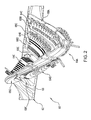
- FIG. 2 shows an exemplary investment casting core assembly 60.
- the assembly includes one or more ceramic cores, illustrated in FIG. 2 as a single ceramic feed core 62, and a number of refractory metal cores (RMCs) 64A-64E.
- RMCs refractory metal cores
- Exemplary RMCs are formed from molybdenum sheet stock and may have a protective coating (e.g., ceramic).
- Alternative RMC substrate materials include refractory metal-based alloys and intermetallics.
- the RMCs 64A-64E respectively form the circuits 40A-40E in the cast part.
- the feed core 62 includes a proximal root 66 and a series of spanwise portions 68A-68G. The spanwise portions respectively form the passageways 30A-30G in the cast part.
- Each of the exemplary RMCs includes a main body 80.
- the body 80 has first and second faces 82 and 84 and may have a number of apertures 86 for forming pedestals, dividing walls, or other features in the associated circuit 40A-40E.
- the body extends between first and second spanwise ends 88 and 90 and from an inlet end 92 to an outlet end 94.
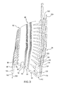
- an array of tabs 96 extend from the body 80.
- the tabs have proximal portions 98 bent/curved to orient the tab away from the local orientation of the body 80.
- Exemplary tabs 96 have straight terminal portions 100 extending to distal ends 102. When assembled to the feed core 60, the distal ends 102 engage the feed core (e.g., contacting a surface of or received within a compartment of the associated spanwise portion(s) 68A-68G).
- first and second arrays of tabs 110 and 112 extend from the body 80.
- the tabs 110 and 112 have proximal portions 114 and 116, respectively, bent/curved to orient the tab away from the local orientation of the body 80.
- the exemplary tabs 110 and 112 have straight terminal portions 118 and 120, respectively, extending to distal ends 122 and 124.
- the distal ends 122 and 124 are positioned to engage a die assembly (discussed below) for molding the pattern wax over the core assembly.
- the tabs 96 form the circuit inlets 42 and the tabs 110 and 112 form the circuit outlets 44 and 46, respectively.
- the terminal portions 100 of the tabs 96 have central axes 520.
- the terminal portions 118 and 120 of the tabs 110 and 112 have respective central axes 522 and 524.
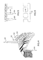
- FIG. 4 shows the exemplary axes 522 as parallel to each other in spanwise projection.
- the exemplary axes 524 are parallel to each other in spanwise projection.
- the axes 522 and 524 are also parallel to each other.
- the exemplary axes 520 are parallel to each other.
- the axes may be fully parallel to each other (e.g., not merely in a spanwise projection).
- FIG. 5 shows the tabs 96 as parallel when viewed approximately streamwise.
- FIG. 5 shows the tabs 96 as parallel when viewed approximately streamwise.
- ⁇ 2 and ⁇ 3 may vary spanwise. For example, they may be well under 90° at one spanwise end, transitioning to over 90° at the other. Exemplary low values for ⁇ 3 are less than 80°, more particularly about 30-75° or 40-70°. Exemplary larger values are the supplements (180° - x) of these.
- FIG. 6 shows an alternate group of tabs 140 connected by a terminal bridging portion 142 (e.g., distinguished from the free tips of other tabs). This construction may provide greater handling robustness.
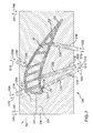
- FIG. 7 shows a pattern-forming die assembly 200.
- the assembly 200 includes two or more die main elements 202 and 204.
- the assembly 200 also includes a number of die inserts 210A-210E, each carried by an associated one of the die main elements 202 or 204.
- the die assembly defines an internal surface 220 forming a compartment for containing the core assembly 60 and molding the pattern wax 222 over the core assembly 60.
- the die main elements 202 and 204 may be respectively identified as upper and lower die elements, although no absolute orientation is required.
- such die elements are installed to each other by a linear insertion in a direction 540 and, after molding, are separated by extraction in an opposite direction 541. With two such main elements, this extraction is known as a single pull.
- some pattern configurations do not permit single pull molding because the shape of the molded wax may create a backlocking effect. In such a situation, there may be an additional main element.
- FIG. 7 shows, in broken line, such an additional element 224 and its associated pull direction 542.
- the tabs if not oriented parallel to the pull of the associated die main element, may cause backlocking.
- the assembly 200 utilizes the inserts 210A-210E.
- Each of the inserts 210A-210E is received in an associated compartment 230A-230E in the associated die main element 202 or 204.
- Each insert 210A-210E includes an end surface 232 which ultimately forms a part of the surface 220. Extending inward from the surface 232 are rows of compartments 234 and 236. The compartments 234 and 236 are positioned to receive the terminal portions of the associated outlet tabs 110 and 112.
- the RMCs may be preassembled to the feedcore.
- the RMCs may be positioned relative to the feedcore such as by wax pads (not shown) between the RMC main bodies and the feedcore.
- the RMCs may be secured to the feedcore such as by melted wax drops or a ceramic adhesive along the contact region between the RMC inlet end terminal portions 100 and the feedcore.
- the die main elements are initially assembled around the core assembly 60 with the inserts 210A-210E fully or slightly retracted.
- the inserts 210A and 210E are, then, inserted in respective directions 550A-550E.
- the terminal portions 118 and 120 of each RMC are received by the associated compartments 234 and 236 of the associated insert 210A-210E.
- the inserts 210A-210E may be fully or partially retracted in a direction 551A-551E, opposite the associated direction 550A-550E.
- the retraction may be simultaneous or staged.
- the inserts in one of the die halves e.g., 210A and 210B in the upper die half 202
- the upper die half 202 may then be disengaged from the lower die half 204 and pattern by extraction in the direction 541.
- the backlocking of the inserts 210C-210E to their associated RMCs helps maintain the pattern engaged to the lower die half. Thereafter, the inserts 210C-210E may be retracted to permit removal of the pattern from the lower die half (e.g., by lifting the pattern in the direction 541).
Landscapes
- Engineering & Computer Science (AREA)
- Mechanical Engineering (AREA)
- Molds, Cores, And Manufacturing Methods Thereof (AREA)
Applications Claiming Priority (1)
| Application Number | Priority Date | Filing Date | Title |
|---|---|---|---|
| US11/219,156 US7185695B1 (en) | 2005-09-01 | 2005-09-01 | Investment casting pattern manufacture |
Publications (3)
| Publication Number | Publication Date |
|---|---|
| EP1772209A2 true EP1772209A2 (fr) | 2007-04-11 |
| EP1772209A3 EP1772209A3 (fr) | 2008-05-21 |
| EP1772209B1 EP1772209B1 (fr) | 2009-12-16 |
Family
ID=37622476
Family Applications (1)
| Application Number | Title | Priority Date | Filing Date |
|---|---|---|---|
| EP06253455A Not-in-force EP1772209B1 (fr) | 2005-09-01 | 2006-06-30 | Fabrication d'un modèle perdu |
Country Status (4)
| Country | Link |
|---|---|
| US (3) | US7185695B1 (fr) |
| EP (1) | EP1772209B1 (fr) |
| JP (1) | JP2007061902A (fr) |
| DE (1) | DE602006011095D1 (fr) |
Cited By (2)
| Publication number | Priority date | Publication date | Assignee | Title |
|---|---|---|---|---|
| EP1886745A1 (fr) * | 2006-08-10 | 2008-02-13 | United Technologies Corporation | Joints d'air externes de lames, et procédé de fabrication |
| EP1927414A3 (fr) * | 2006-11-30 | 2008-07-30 | United Technologies Corporation | Fentes de soufflage à pointe défini par RMC pour pales de turbine |
Families Citing this family (52)
| Publication number | Priority date | Publication date | Assignee | Title |
|---|---|---|---|---|
| US8066052B2 (en) * | 2007-06-07 | 2011-11-29 | United Technologies Corporation | Cooled wall thickness control |
| US8133553B2 (en) | 2007-06-18 | 2012-03-13 | Zimmer, Inc. | Process for forming a ceramic layer |
| US8309521B2 (en) * | 2007-06-19 | 2012-11-13 | Zimmer, Inc. | Spacer with a coating thereon for use with an implant device |
| US20110230973A1 (en) * | 2007-10-10 | 2011-09-22 | Zimmer, Inc. | Method for bonding a tantalum structure to a cobalt-alloy substrate |
| US8608049B2 (en) * | 2007-10-10 | 2013-12-17 | Zimmer, Inc. | Method for bonding a tantalum structure to a cobalt-alloy substrate |
| US20090198286A1 (en) * | 2008-02-05 | 2009-08-06 | Zimmer, Inc. | Bone fracture fixation system |
| US7882885B2 (en) * | 2008-02-18 | 2011-02-08 | United Technologies Corporation | Systems and methods for reducing the potential for riser backfilling during investment casting |
| US8157527B2 (en) * | 2008-07-03 | 2012-04-17 | United Technologies Corporation | Airfoil with tapered radial cooling passage |
| FR2933884B1 (fr) * | 2008-07-16 | 2012-07-27 | Snecma | Procede de fabrication d'une piece d'aubage. |
| US8572844B2 (en) * | 2008-08-29 | 2013-11-05 | United Technologies Corporation | Airfoil with leading edge cooling passage |
| US8303252B2 (en) * | 2008-10-16 | 2012-11-06 | United Technologies Corporation | Airfoil with cooling passage providing variable heat transfer rate |
| WO2010044800A1 (fr) * | 2008-10-17 | 2010-04-22 | Brp Us Inc. | Procédé et appareil de coulée de modèle consommable |
| US8100165B2 (en) * | 2008-11-17 | 2012-01-24 | United Technologies Corporation | Investment casting cores and methods |
| US8113780B2 (en) * | 2008-11-21 | 2012-02-14 | United Technologies Corporation | Castings, casting cores, and methods |
| US8109725B2 (en) * | 2008-12-15 | 2012-02-07 | United Technologies Corporation | Airfoil with wrapped leading edge cooling passage |
| US8313301B2 (en) * | 2009-01-30 | 2012-11-20 | United Technologies Corporation | Cooled turbine blade shroud |
| US20110135446A1 (en) * | 2009-12-04 | 2011-06-09 | United Technologies Corporation | Castings, Casting Cores, and Methods |
| US20110132562A1 (en) * | 2009-12-08 | 2011-06-09 | Merrill Gary B | Waxless precision casting process |
| US8807198B2 (en) | 2010-11-05 | 2014-08-19 | United Technologies Corporation | Die casting system and method utilizing sacrificial core |
| US8291963B1 (en) * | 2011-08-03 | 2012-10-23 | United Technologies Corporation | Hybrid core assembly |
| US9138804B2 (en) | 2012-01-11 | 2015-09-22 | United Technologies Corporation | Core for a casting process |
| US20130280081A1 (en) | 2012-04-24 | 2013-10-24 | Mark F. Zelesky | Gas turbine engine airfoil geometries and cores for manufacturing process |
| US20130340966A1 (en) * | 2012-06-21 | 2013-12-26 | United Technologies Corporation | Blade outer air seal hybrid casting core |
| US9879546B2 (en) * | 2012-06-21 | 2018-01-30 | United Technologies Corporation | Airfoil cooling circuits |
| US10100646B2 (en) * | 2012-08-03 | 2018-10-16 | United Technologies Corporation | Gas turbine engine component cooling circuit |
| US9511418B2 (en) * | 2012-10-01 | 2016-12-06 | United Technologies Corporation | Method of casting parts using heat reservoir, gating used by such method, and casting made thereby |
| US20140102656A1 (en) * | 2012-10-12 | 2014-04-17 | United Technologies Corporation | Casting Cores and Manufacture Methods |
| US9120144B2 (en) * | 2013-02-06 | 2015-09-01 | Siemens Aktiengesellschaft | Casting core for twisted gas turbine engine airfoil having a twisted rib |
| EP2964891B1 (fr) | 2013-03-05 | 2019-06-12 | Rolls-Royce North American Technologies, Inc. | Agencement de composant pour moteur à turbine à gaz |
| US9874110B2 (en) * | 2013-03-07 | 2018-01-23 | Rolls-Royce North American Technologies Inc. | Cooled gas turbine engine component |
| US9835035B2 (en) | 2013-03-12 | 2017-12-05 | Howmet Corporation | Cast-in cooling features especially for turbine airfoils |
| WO2014197061A2 (fr) | 2013-03-15 | 2014-12-11 | United Technologies Corporation | Trou de refroidissement de film formé de turbine à gaz |
| US20160222794A1 (en) * | 2013-09-09 | 2016-08-04 | United Technologies Corporation | Incidence tolerant engine component |
| US9132476B2 (en) * | 2013-10-31 | 2015-09-15 | Siemens Aktiengesellschaft | Multi-wall gas turbine airfoil cast using a ceramic core formed with a fugitive insert and method of manufacturing same |
| US10329916B2 (en) | 2014-05-01 | 2019-06-25 | United Technologies Corporation | Splayed tip features for gas turbine engine airfoil |
| US9988910B2 (en) * | 2015-01-30 | 2018-06-05 | United Technologies Corporation | Staggered core printout |
| CN104959795A (zh) * | 2015-06-17 | 2015-10-07 | 遵义航天新力精密铸锻有限公司 | 一种雷达大型散热冷却循环控制系统的加工方法 |
| US10046389B2 (en) | 2015-12-17 | 2018-08-14 | General Electric Company | Method and assembly for forming components having internal passages using a jacketed core |
| US9987677B2 (en) | 2015-12-17 | 2018-06-05 | General Electric Company | Method and assembly for forming components having internal passages using a jacketed core |
| US10099283B2 (en) | 2015-12-17 | 2018-10-16 | General Electric Company | Method and assembly for forming components having an internal passage defined therein |
| US10099284B2 (en) | 2015-12-17 | 2018-10-16 | General Electric Company | Method and assembly for forming components having a catalyzed internal passage defined therein |
| US10099276B2 (en) | 2015-12-17 | 2018-10-16 | General Electric Company | Method and assembly for forming components having an internal passage defined therein |
| US10137499B2 (en) | 2015-12-17 | 2018-11-27 | General Electric Company | Method and assembly for forming components having an internal passage defined therein |
| US9968991B2 (en) | 2015-12-17 | 2018-05-15 | General Electric Company | Method and assembly for forming components having internal passages using a lattice structure |
| US9579714B1 (en) | 2015-12-17 | 2017-02-28 | General Electric Company | Method and assembly for forming components having internal passages using a lattice structure |
| US10118217B2 (en) | 2015-12-17 | 2018-11-06 | General Electric Company | Method and assembly for forming components having internal passages using a jacketed core |
| US10150158B2 (en) | 2015-12-17 | 2018-12-11 | General Electric Company | Method and assembly for forming components having internal passages using a jacketed core |
| US10335853B2 (en) | 2016-04-27 | 2019-07-02 | General Electric Company | Method and assembly for forming components using a jacketed core |
| US10286450B2 (en) | 2016-04-27 | 2019-05-14 | General Electric Company | Method and assembly for forming components using a jacketed core |
| US10556269B1 (en) | 2017-03-29 | 2020-02-11 | United Technologies Corporation | Apparatus for and method of making multi-walled passages in components |
| US10596621B1 (en) | 2017-03-29 | 2020-03-24 | United Technologies Corporation | Method of making complex internal passages in turbine airfoils |
| US10808571B2 (en) * | 2017-06-22 | 2020-10-20 | Raytheon Technologies Corporation | Gaspath component including minicore plenums |
Citations (2)
| Publication number | Priority date | Publication date | Assignee | Title |
|---|---|---|---|---|
| US5291654A (en) | 1993-03-29 | 1994-03-08 | United Technologies Corporation | Method for producing hollow investment castings |
| US20050274478A1 (en) | 2004-06-14 | 2005-12-15 | Verner Carl R | Investment casting |
Family Cites Families (53)
| Publication number | Priority date | Publication date | Assignee | Title |
|---|---|---|---|---|
| US4618262A (en) * | 1984-04-13 | 1986-10-21 | Applied Materials, Inc. | Laser interferometer system and method for monitoring and controlling IC processing |
| DE3650562T2 (de) * | 1985-04-11 | 1997-03-20 | Toyo Communication Equip | Piezoelektrischer resonator zur erzeugung von oberschwingungen |
| US4944836A (en) * | 1985-10-28 | 1990-07-31 | International Business Machines Corporation | Chem-mech polishing method for producing coplanar metal/insulator films on a substrate |
| US5668057A (en) * | 1991-03-13 | 1997-09-16 | Matsushita Electric Industrial Co., Ltd. | Methods of manufacture for electronic components having high-frequency elements |
| US6614529B1 (en) * | 1992-12-28 | 2003-09-02 | Applied Materials, Inc. | In-situ real-time monitoring technique and apparatus for endpoint detection of thin films during chemical/mechanical polishing planarization |
| JPH06350376A (ja) * | 1993-01-25 | 1994-12-22 | Matsushita Electric Ind Co Ltd | 気密封止された圧電デバイスおよび気密封止パッケージ |
| EP0662241A1 (fr) * | 1993-04-28 | 1995-07-12 | Applied Materials, Inc. | Procede et appareil de detection du point final d'une gravure en retrait |
| FR2718231B1 (fr) * | 1994-04-05 | 1996-06-21 | Sofie | Procédé et dispositif pour quantifier in situ la morphologie et l'épaisseur dans une zone localisée d'une couche superficielle en cours de traitement sur une structure à couches minces . |
| US5480747A (en) * | 1994-11-21 | 1996-01-02 | Sematech, Inc. | Attenuated phase shifting mask with buried absorbers |
| DE69510032T2 (de) * | 1995-03-31 | 2000-01-27 | International Business Machines Corp., Armonk | Verfahren und Gerät zur Überwachung des Trockenätzens eines dielektrischen Films bis zu einer gegebenen Dicke |
| JP3620554B2 (ja) * | 1996-03-25 | 2005-02-16 | 信越半導体株式会社 | 半導体ウェーハ製造方法 |
| JP3252702B2 (ja) * | 1996-03-28 | 2002-02-04 | 信越半導体株式会社 | 気相エッチング工程を含む半導体単結晶鏡面ウエーハの製造方法およびこの方法で製造される半導体単結晶鏡面ウエーハ |
| US5928532A (en) * | 1996-11-11 | 1999-07-27 | Tokyo Electron Limited | Method of detecting end point of plasma processing and apparatus for the same |
| US6049702A (en) * | 1997-12-04 | 2000-04-11 | Rockwell Science Center, Llc | Integrated passive transceiver section |
| JPH11176815A (ja) * | 1997-12-15 | 1999-07-02 | Ricoh Co Ltd | ドライエッチングの終点判定方法およびドライエッチング装置 |
| US6297064B1 (en) * | 1998-02-03 | 2001-10-02 | Tokyo Electron Yamanashi Limited | End point detecting method for semiconductor plasma processing |
| US6081334A (en) * | 1998-04-17 | 2000-06-27 | Applied Materials, Inc | Endpoint detection for semiconductor processes |
| JP3647267B2 (ja) * | 1998-05-29 | 2005-05-11 | キヤノン株式会社 | 面発光レーザーを用いた表面プラズモン共鳴センサ装置 |
| JP3627907B2 (ja) * | 1999-05-21 | 2005-03-09 | 信越化学工業株式会社 | フォトマスク用合成石英ガラス基板の製造方法 |
| AU5631200A (en) * | 1999-06-22 | 2001-01-09 | President And Fellows Of Harvard College | Control of solid state dimensional features |
| US7118657B2 (en) * | 1999-06-22 | 2006-10-10 | President And Fellows Of Harvard College | Pulsed ion beam control of solid state features |
| FR2797140B1 (fr) * | 1999-07-30 | 2001-11-02 | Thomson Csf Sextant | Procede de fabrication de connexions traversantes dans un substrat et substrat equipe de telles connexions |
| JP2001066248A (ja) * | 1999-08-26 | 2001-03-16 | Fuji Photo Film Co Ltd | 表面プラズモンセンサー |
| ES2584553T3 (es) * | 1999-10-06 | 2016-09-28 | Becton Dickinson And Company | Nanopartículas compuestas espectroscópicamente activas superficialmente potenciadas |
| DE19962028A1 (de) * | 1999-12-22 | 2001-06-28 | Philips Corp Intellectual Pty | Filteranordnung |
| JP2001244240A (ja) * | 2000-02-25 | 2001-09-07 | Speedfam Co Ltd | 半導体ウエハの製造方法 |
| TW492106B (en) * | 2000-06-20 | 2002-06-21 | Hitachi Ltd | Inspection method for thickness of film to be processed using luminous beam-splitter and method of film processing |
| AU2001269528A1 (en) * | 2000-07-17 | 2002-01-30 | Nagaura, Kumiko | Piezoelectric device and acousto-electric transducer and method for manufacturing the same |
| JP3639809B2 (ja) * | 2000-09-01 | 2005-04-20 | キヤノン株式会社 | 電子放出素子,電子放出装置,発光装置及び画像表示装置 |
| US6426296B1 (en) * | 2000-09-08 | 2002-07-30 | The United States Of America As Represented By The Administrator Of The National Aeronautics And Space Administration | Method and apparatus for obtaining a precision thickness in semiconductor and other wafers |
| KR100354442B1 (ko) * | 2000-12-11 | 2002-09-28 | 삼성전자 주식회사 | 반도체 장치의 스핀 온 글래스 절연막 형성 방법 |
| DE10063491A1 (de) * | 2000-12-20 | 2002-06-27 | Bayer Ag | Saure Polierslurry für das chemisch-mechanische Polieren von SiO¶2¶-Isolationsschichten |
| JP4071476B2 (ja) * | 2001-03-21 | 2008-04-02 | 株式会社東芝 | 半導体ウェーハ及び半導体ウェーハの製造方法 |
| US6862398B2 (en) * | 2001-03-30 | 2005-03-01 | Texas Instruments Incorporated | System for directed molecular interaction in surface plasmon resonance analysis |
| US6920765B2 (en) * | 2001-06-04 | 2005-07-26 | The Regents Of The University Of California | Combined advanced finishing and UV laser conditioning process for producing damage resistant optics |
| US6710681B2 (en) * | 2001-07-13 | 2004-03-23 | Agilent Technologies, Inc. | Thin film bulk acoustic resonator (FBAR) and inductor on a monolithic substrate and method of fabricating the same |
| TWI220423B (en) * | 2001-08-30 | 2004-08-21 | Hrl Lab Llc | A method of fabrication of a sensor |
| US6637500B2 (en) | 2001-10-24 | 2003-10-28 | United Technologies Corporation | Cores for use in precision investment casting |
| JP3996788B2 (ja) * | 2002-02-18 | 2007-10-24 | アイシン高丘株式会社 | 金属製品の鋳造装置 |
| AU2003272195A1 (en) * | 2002-04-30 | 2004-01-06 | Hrl Laboratories, Llc | Quartz-based nanoresonators and method of fabricating same |
| TW540173B (en) * | 2002-05-03 | 2003-07-01 | Asia Pacific Microsystems Inc | Bulk acoustic device having integrated fine-tuning and trimming devices |
| WO2004073824A2 (fr) * | 2003-02-20 | 2004-09-02 | Dow Global Technologies Inc. | Procede de synthese de polyarylenes et polyarylenes obtenus par ce procede |
| KR100517841B1 (ko) * | 2003-02-22 | 2005-09-30 | 주식회사 엠에스솔루션 | 체적탄성파 공진기 밴드 패스 필터, 이를 포함하는듀플렉서 및 그 제조 방법 |
| US6946928B2 (en) * | 2003-10-30 | 2005-09-20 | Agilent Technologies, Inc. | Thin-film acoustically-coupled transformer |
| US6929054B2 (en) * | 2003-12-19 | 2005-08-16 | United Technologies Corporation | Investment casting cores |
| KR100565799B1 (ko) * | 2003-12-22 | 2006-03-29 | 삼성전자주식회사 | 일체화된 FBAR 및 Isolation부를 사용하여제조된 듀플렉서 및 그 제조 방법 |
| US7172012B1 (en) * | 2004-07-14 | 2007-02-06 | United Technologies Corporation | Investment casting |
| KR100760780B1 (ko) * | 2004-09-28 | 2007-09-21 | 후지쓰 메디아 데바이스 가부시키가이샤 | 분파기 |
| JP2006135447A (ja) * | 2004-11-02 | 2006-05-25 | Fujitsu Media Device Kk | 分波器 |
| JP4762531B2 (ja) * | 2004-11-30 | 2011-08-31 | 太陽誘電株式会社 | 電子部品及びその製造方法 |
| US7555824B2 (en) * | 2006-08-09 | 2009-07-07 | Hrl Laboratories, Llc | Method for large scale integration of quartz-based devices |
| US7605916B2 (en) * | 2006-09-21 | 2009-10-20 | Intel Corporation | Online analyte detection by surface enhanced Raman scattering (SERS) |
| US7663196B2 (en) * | 2007-02-09 | 2010-02-16 | Freescale Semiconductor, Inc. | Integrated passive device and method of fabrication |
-
2005
- 2005-09-01 US US11/219,156 patent/US7185695B1/en not_active Expired - Lifetime
-
2006
- 2006-06-29 JP JP2006178910A patent/JP2007061902A/ja active Pending
- 2006-06-30 EP EP06253455A patent/EP1772209B1/fr not_active Not-in-force
- 2006-06-30 DE DE602006011095T patent/DE602006011095D1/de active Active
- 2006-09-19 US US11/523,960 patent/US7258156B2/en not_active Expired - Lifetime
-
2007
- 2007-07-31 US US11/831,028 patent/US7438118B2/en not_active Expired - Lifetime
Patent Citations (2)
| Publication number | Priority date | Publication date | Assignee | Title |
|---|---|---|---|---|
| US5291654A (en) | 1993-03-29 | 1994-03-08 | United Technologies Corporation | Method for producing hollow investment castings |
| US20050274478A1 (en) | 2004-06-14 | 2005-12-15 | Verner Carl R | Investment casting |
Cited By (2)
| Publication number | Priority date | Publication date | Assignee | Title |
|---|---|---|---|---|
| EP1886745A1 (fr) * | 2006-08-10 | 2008-02-13 | United Technologies Corporation | Joints d'air externes de lames, et procédé de fabrication |
| EP1927414A3 (fr) * | 2006-11-30 | 2008-07-30 | United Technologies Corporation | Fentes de soufflage à pointe défini par RMC pour pales de turbine |
Also Published As
| Publication number | Publication date |
|---|---|
| US7185695B1 (en) | 2007-03-06 |
| EP1772209B1 (fr) | 2009-12-16 |
| EP1772209A3 (fr) | 2008-05-21 |
| US20080060781A1 (en) | 2008-03-13 |
| US7258156B2 (en) | 2007-08-21 |
| US7438118B2 (en) | 2008-10-21 |
| US20070044933A1 (en) | 2007-03-01 |
| US20070044934A1 (en) | 2007-03-01 |
| JP2007061902A (ja) | 2007-03-15 |
| DE602006011095D1 (de) | 2010-01-28 |
Similar Documents
| Publication | Publication Date | Title |
|---|---|---|
| EP1772209B1 (fr) | Fabrication d'un modèle perdu | |
| US7306026B2 (en) | Cooled turbine airfoils and methods of manufacture | |
| EP1616642B1 (fr) | Coulée de précisionà la cire perdue | |
| EP2000232B1 (fr) | Contrôle d'épaisseur de paroi refroidie | |
| US8137068B2 (en) | Castings, casting cores, and methods | |
| AU2005201580B2 (en) | Investment casting | |
| US7779892B2 (en) | Investment casting cores and methods | |
| EP2189230B1 (fr) | Moulages, noyaux de moulage et procédés | |
| EP1857199B1 (fr) | Conception d'ensemble de noyau de coulée | |
| EP2298469A1 (fr) | Noyeaux pour la coulée en cire perdue et leurs utilisation en fonderie en cire perdue | |
| EP1923152B1 (fr) | Procédé de coulage d'aube de turbine | |
| WO2014035522A2 (fr) | Noyau de moulage hybride pour joint extérieur d'aube étanche à l'air |
Legal Events
| Date | Code | Title | Description |
|---|---|---|---|
| PUAI | Public reference made under article 153(3) epc to a published international application that has entered the european phase |
Free format text: ORIGINAL CODE: 0009012 |
|
| AK | Designated contracting states |
Kind code of ref document: A2 Designated state(s): AT BE BG CH CY CZ DE DK EE ES FI FR GB GR HU IE IS IT LI LT LU LV MC NL PL PT RO SE SI SK TR |
|
| AX | Request for extension of the european patent |
Extension state: AL BA HR MK YU |
|
| PUAL | Search report despatched |
Free format text: ORIGINAL CODE: 0009013 |
|
| AK | Designated contracting states |
Kind code of ref document: A3 Designated state(s): AT BE BG CH CY CZ DE DK EE ES FI FR GB GR HU IE IS IT LI LT LU LV MC NL PL PT RO SE SI SK TR |
|
| AX | Request for extension of the european patent |
Extension state: AL BA HR MK RS |
|
| RIC1 | Information provided on ipc code assigned before grant |
Ipc: B22D 17/24 20060101ALI20080417BHEP Ipc: B22C 9/04 20060101ALI20080417BHEP Ipc: B22C 9/10 20060101ALI20080417BHEP Ipc: B22C 7/02 20060101AFI20070301BHEP Ipc: B22C 21/14 20060101ALI20080417BHEP Ipc: B22C 9/06 20060101ALI20080417BHEP |
|
| 17P | Request for examination filed |
Effective date: 20080630 |
|
| AKX | Designation fees paid |
Designated state(s): DE FR GB |
|
| GRAP | Despatch of communication of intention to grant a patent |
Free format text: ORIGINAL CODE: EPIDOSNIGR1 |
|
| GRAS | Grant fee paid |
Free format text: ORIGINAL CODE: EPIDOSNIGR3 |
|
| GRAA | (expected) grant |
Free format text: ORIGINAL CODE: 0009210 |
|
| AK | Designated contracting states |
Kind code of ref document: B1 Designated state(s): DE FR GB |
|
| REG | Reference to a national code |
Ref country code: GB Ref legal event code: FG4D |
|
| REF | Corresponds to: |
Ref document number: 602006011095 Country of ref document: DE Date of ref document: 20100128 Kind code of ref document: P |
|
| PLBE | No opposition filed within time limit |
Free format text: ORIGINAL CODE: 0009261 |
|
| STAA | Information on the status of an ep patent application or granted ep patent |
Free format text: STATUS: NO OPPOSITION FILED WITHIN TIME LIMIT |
|
| 26N | No opposition filed |
Effective date: 20100917 |
|
| REG | Reference to a national code |
Ref country code: FR Ref legal event code: ST Effective date: 20110228 |
|
| PG25 | Lapsed in a contracting state [announced via postgrant information from national office to epo] |
Ref country code: FR Free format text: LAPSE BECAUSE OF NON-PAYMENT OF DUE FEES Effective date: 20100630 |
|
| REG | Reference to a national code |
Ref country code: DE Ref legal event code: R082 Ref document number: 602006011095 Country of ref document: DE Representative=s name: SCHMITT-NILSON SCHRAUD WAIBEL WOHLFROM PATENTA, DE |
|
| REG | Reference to a national code |
Ref country code: DE Ref legal event code: R082 Ref document number: 602006011095 Country of ref document: DE Representative=s name: SCHMITT-NILSON SCHRAUD WAIBEL WOHLFROM PATENTA, DE Ref country code: DE Ref legal event code: R081 Ref document number: 602006011095 Country of ref document: DE Owner name: UNITED TECHNOLOGIES CORP. (N.D.GES.D. STAATES , US Free format text: FORMER OWNER: UNITED TECHNOLOGIES CORP., HARTFORD, CONN., US |
|
| PGFP | Annual fee paid to national office [announced via postgrant information from national office to epo] |
Ref country code: DE Payment date: 20190521 Year of fee payment: 14 |
|
| PGFP | Annual fee paid to national office [announced via postgrant information from national office to epo] |
Ref country code: GB Payment date: 20190522 Year of fee payment: 14 |
|
| REG | Reference to a national code |
Ref country code: DE Ref legal event code: R119 Ref document number: 602006011095 Country of ref document: DE |
|
| GBPC | Gb: european patent ceased through non-payment of renewal fee |
Effective date: 20200630 |
|
| PG25 | Lapsed in a contracting state [announced via postgrant information from national office to epo] |
Ref country code: GB Free format text: LAPSE BECAUSE OF NON-PAYMENT OF DUE FEES Effective date: 20200630 |
|
| PG25 | Lapsed in a contracting state [announced via postgrant information from national office to epo] |
Ref country code: DE Free format text: LAPSE BECAUSE OF NON-PAYMENT OF DUE FEES Effective date: 20210101 |