EP1772268B1 - Tintenstrahlaufzeichnungsgerät und dessen Steuerverfahren - Google Patents
Tintenstrahlaufzeichnungsgerät und dessen Steuerverfahren Download PDFInfo
- Publication number
- EP1772268B1 EP1772268B1 EP06020961A EP06020961A EP1772268B1 EP 1772268 B1 EP1772268 B1 EP 1772268B1 EP 06020961 A EP06020961 A EP 06020961A EP 06020961 A EP06020961 A EP 06020961A EP 1772268 B1 EP1772268 B1 EP 1772268B1
- Authority
- EP
- European Patent Office
- Prior art keywords
- ink
- pressure chamber
- state
- passage
- pressure
- Prior art date
- Legal status (The legal status is an assumption and is not a legal conclusion. Google has not performed a legal analysis and makes no representation as to the accuracy of the status listed.)
- Active
Links
- 238000000034 method Methods 0.000 title claims description 26
- 230000008859 change Effects 0.000 claims description 24
- 239000012530 fluid Substances 0.000 description 13
- 230000014509 gene expression Effects 0.000 description 10
- 238000010586 diagram Methods 0.000 description 9
- 238000004088 simulation Methods 0.000 description 7
- 230000009467 reduction Effects 0.000 description 5
- 230000007704 transition Effects 0.000 description 5
- 230000006866 deterioration Effects 0.000 description 4
- 230000005684 electric field Effects 0.000 description 4
- 230000006870 function Effects 0.000 description 4
- 238000003475 lamination Methods 0.000 description 4
- 230000004048 modification Effects 0.000 description 3
- 238000012986 modification Methods 0.000 description 3
- 238000003825 pressing Methods 0.000 description 3
- 238000011144 upstream manufacturing Methods 0.000 description 3
- 238000001514 detection method Methods 0.000 description 2
- 230000000694 effects Effects 0.000 description 2
- 230000005284 excitation Effects 0.000 description 2
- 229910052451 lead zirconate titanate Inorganic materials 0.000 description 2
- 230000005499 meniscus Effects 0.000 description 2
- 230000000630 rising effect Effects 0.000 description 2
- 239000000853 adhesive Substances 0.000 description 1
- 230000001070 adhesive effect Effects 0.000 description 1
- 238000004364 calculation method Methods 0.000 description 1
- 229910010293 ceramic material Inorganic materials 0.000 description 1
- 238000006243 chemical reaction Methods 0.000 description 1
- 239000003086 colorant Substances 0.000 description 1
- 230000006835 compression Effects 0.000 description 1
- 238000007906 compression Methods 0.000 description 1
- 238000010276 construction Methods 0.000 description 1
- 230000002542 deteriorative effect Effects 0.000 description 1
- 230000005621 ferroelectricity Effects 0.000 description 1
- 239000011521 glass Substances 0.000 description 1
- PCHJSUWPFVWCPO-UHFFFAOYSA-N gold Chemical compound [Au] PCHJSUWPFVWCPO-UHFFFAOYSA-N 0.000 description 1
- 239000010931 gold Substances 0.000 description 1
- 229910052737 gold Inorganic materials 0.000 description 1
- HFGPZNIAWCZYJU-UHFFFAOYSA-N lead zirconate titanate Chemical compound [O-2].[O-2].[O-2].[O-2].[O-2].[Ti+4].[Zr+4].[Pb+2] HFGPZNIAWCZYJU-UHFFFAOYSA-N 0.000 description 1
- 239000011159 matrix material Substances 0.000 description 1
- 239000007769 metal material Substances 0.000 description 1
- 230000010287 polarization Effects 0.000 description 1
- 238000009774 resonance method Methods 0.000 description 1
- 229920002379 silicone rubber Polymers 0.000 description 1
Images





Classifications
-
- B—PERFORMING OPERATIONS; TRANSPORTING
- B41—PRINTING; LINING MACHINES; TYPEWRITERS; STAMPS
- B41J—TYPEWRITERS; SELECTIVE PRINTING MECHANISMS, i.e. MECHANISMS PRINTING OTHERWISE THAN FROM A FORME; CORRECTION OF TYPOGRAPHICAL ERRORS
- B41J2/00—Typewriters or selective printing mechanisms characterised by the printing or marking process for which they are designed
- B41J2/005—Typewriters or selective printing mechanisms characterised by the printing or marking process for which they are designed characterised by bringing liquid or particles selectively into contact with a printing material
- B41J2/01—Ink jet
- B41J2/135—Nozzles
- B41J2/14—Structure thereof only for on-demand ink jet heads
- B41J2/14201—Structure of print heads with piezoelectric elements
- B41J2/14209—Structure of print heads with piezoelectric elements of finger type, chamber walls consisting integrally of piezoelectric material
-
- B—PERFORMING OPERATIONS; TRANSPORTING
- B41—PRINTING; LINING MACHINES; TYPEWRITERS; STAMPS
- B41J—TYPEWRITERS; SELECTIVE PRINTING MECHANISMS, i.e. MECHANISMS PRINTING OTHERWISE THAN FROM A FORME; CORRECTION OF TYPOGRAPHICAL ERRORS
- B41J2/00—Typewriters or selective printing mechanisms characterised by the printing or marking process for which they are designed
- B41J2/005—Typewriters or selective printing mechanisms characterised by the printing or marking process for which they are designed characterised by bringing liquid or particles selectively into contact with a printing material
- B41J2/01—Ink jet
- B41J2/015—Ink jet characterised by the jet generation process
- B41J2/04—Ink jet characterised by the jet generation process generating single droplets or particles on demand
- B41J2/045—Ink jet characterised by the jet generation process generating single droplets or particles on demand by pressure, e.g. electromechanical transducers
- B41J2/04501—Control methods or devices therefor, e.g. driver circuits, control circuits
- B41J2/04581—Control methods or devices therefor, e.g. driver circuits, control circuits controlling heads based on piezoelectric elements
-
- B—PERFORMING OPERATIONS; TRANSPORTING
- B41—PRINTING; LINING MACHINES; TYPEWRITERS; STAMPS
- B41J—TYPEWRITERS; SELECTIVE PRINTING MECHANISMS, i.e. MECHANISMS PRINTING OTHERWISE THAN FROM A FORME; CORRECTION OF TYPOGRAPHICAL ERRORS
- B41J2/00—Typewriters or selective printing mechanisms characterised by the printing or marking process for which they are designed
- B41J2/005—Typewriters or selective printing mechanisms characterised by the printing or marking process for which they are designed characterised by bringing liquid or particles selectively into contact with a printing material
- B41J2/01—Ink jet
- B41J2/015—Ink jet characterised by the jet generation process
- B41J2/04—Ink jet characterised by the jet generation process generating single droplets or particles on demand
- B41J2/045—Ink jet characterised by the jet generation process generating single droplets or particles on demand by pressure, e.g. electromechanical transducers
- B41J2/04501—Control methods or devices therefor, e.g. driver circuits, control circuits
- B41J2/04588—Control methods or devices therefor, e.g. driver circuits, control circuits using a specific waveform
-
- B—PERFORMING OPERATIONS; TRANSPORTING
- B41—PRINTING; LINING MACHINES; TYPEWRITERS; STAMPS
- B41J—TYPEWRITERS; SELECTIVE PRINTING MECHANISMS, i.e. MECHANISMS PRINTING OTHERWISE THAN FROM A FORME; CORRECTION OF TYPOGRAPHICAL ERRORS
- B41J2/00—Typewriters or selective printing mechanisms characterised by the printing or marking process for which they are designed
- B41J2/005—Typewriters or selective printing mechanisms characterised by the printing or marking process for which they are designed characterised by bringing liquid or particles selectively into contact with a printing material
- B41J2/01—Ink jet
- B41J2/015—Ink jet characterised by the jet generation process
- B41J2/04—Ink jet characterised by the jet generation process generating single droplets or particles on demand
- B41J2/045—Ink jet characterised by the jet generation process generating single droplets or particles on demand by pressure, e.g. electromechanical transducers
- B41J2/04501—Control methods or devices therefor, e.g. driver circuits, control circuits
- B41J2/0459—Height of the driving signal being adjusted
-
- B—PERFORMING OPERATIONS; TRANSPORTING
- B41—PRINTING; LINING MACHINES; TYPEWRITERS; STAMPS
- B41J—TYPEWRITERS; SELECTIVE PRINTING MECHANISMS, i.e. MECHANISMS PRINTING OTHERWISE THAN FROM A FORME; CORRECTION OF TYPOGRAPHICAL ERRORS
- B41J2/00—Typewriters or selective printing mechanisms characterised by the printing or marking process for which they are designed
- B41J2/005—Typewriters or selective printing mechanisms characterised by the printing or marking process for which they are designed characterised by bringing liquid or particles selectively into contact with a printing material
- B41J2/01—Ink jet
- B41J2/015—Ink jet characterised by the jet generation process
- B41J2/04—Ink jet characterised by the jet generation process generating single droplets or particles on demand
- B41J2/045—Ink jet characterised by the jet generation process generating single droplets or particles on demand by pressure, e.g. electromechanical transducers
- B41J2/04501—Control methods or devices therefor, e.g. driver circuits, control circuits
- B41J2/04591—Width of the driving signal being adjusted
-
- B—PERFORMING OPERATIONS; TRANSPORTING
- B41—PRINTING; LINING MACHINES; TYPEWRITERS; STAMPS
- B41J—TYPEWRITERS; SELECTIVE PRINTING MECHANISMS, i.e. MECHANISMS PRINTING OTHERWISE THAN FROM A FORME; CORRECTION OF TYPOGRAPHICAL ERRORS
- B41J2/00—Typewriters or selective printing mechanisms characterised by the printing or marking process for which they are designed
- B41J2/005—Typewriters or selective printing mechanisms characterised by the printing or marking process for which they are designed characterised by bringing liquid or particles selectively into contact with a printing material
- B41J2/01—Ink jet
- B41J2/135—Nozzles
- B41J2/14—Structure thereof only for on-demand ink jet heads
- B41J2/14201—Structure of print heads with piezoelectric elements
- B41J2/14209—Structure of print heads with piezoelectric elements of finger type, chamber walls consisting integrally of piezoelectric material
- B41J2002/14217—Multi layer finger type piezoelectric element
-
- B—PERFORMING OPERATIONS; TRANSPORTING
- B41—PRINTING; LINING MACHINES; TYPEWRITERS; STAMPS
- B41J—TYPEWRITERS; SELECTIVE PRINTING MECHANISMS, i.e. MECHANISMS PRINTING OTHERWISE THAN FROM A FORME; CORRECTION OF TYPOGRAPHICAL ERRORS
- B41J2/00—Typewriters or selective printing mechanisms characterised by the printing or marking process for which they are designed
- B41J2/005—Typewriters or selective printing mechanisms characterised by the printing or marking process for which they are designed characterised by bringing liquid or particles selectively into contact with a printing material
- B41J2/01—Ink jet
- B41J2/135—Nozzles
- B41J2/14—Structure thereof only for on-demand ink jet heads
- B41J2/14201—Structure of print heads with piezoelectric elements
- B41J2/14209—Structure of print heads with piezoelectric elements of finger type, chamber walls consisting integrally of piezoelectric material
- B41J2002/14225—Finger type piezoelectric element on only one side of the chamber
-
- B—PERFORMING OPERATIONS; TRANSPORTING
- B41—PRINTING; LINING MACHINES; TYPEWRITERS; STAMPS
- B41J—TYPEWRITERS; SELECTIVE PRINTING MECHANISMS, i.e. MECHANISMS PRINTING OTHERWISE THAN FROM A FORME; CORRECTION OF TYPOGRAPHICAL ERRORS
- B41J2/00—Typewriters or selective printing mechanisms characterised by the printing or marking process for which they are designed
- B41J2/005—Typewriters or selective printing mechanisms characterised by the printing or marking process for which they are designed characterised by bringing liquid or particles selectively into contact with a printing material
- B41J2/01—Ink jet
- B41J2/135—Nozzles
- B41J2/14—Structure thereof only for on-demand ink jet heads
- B41J2/14201—Structure of print heads with piezoelectric elements
- B41J2002/14306—Flow passage between manifold and chamber
-
- B—PERFORMING OPERATIONS; TRANSPORTING
- B41—PRINTING; LINING MACHINES; TYPEWRITERS; STAMPS
- B41J—TYPEWRITERS; SELECTIVE PRINTING MECHANISMS, i.e. MECHANISMS PRINTING OTHERWISE THAN FROM A FORME; CORRECTION OF TYPOGRAPHICAL ERRORS
- B41J2/00—Typewriters or selective printing mechanisms characterised by the printing or marking process for which they are designed
- B41J2/005—Typewriters or selective printing mechanisms characterised by the printing or marking process for which they are designed characterised by bringing liquid or particles selectively into contact with a printing material
- B41J2/01—Ink jet
- B41J2/135—Nozzles
- B41J2/14—Structure thereof only for on-demand ink jet heads
- B41J2002/14459—Matrix arrangement of the pressure chambers
Definitions
- This invention relates to a combination of an inkjet recording apparatus and ink and a method for controlling the combination.
- ink is ejected from a nozzle when pressure is applied to ink contained in a pressure chamber.
- an inkjet recording apparatus employing a so-called fill before fire method is disclosed in JP-A-2003-305852 , which is capable of applying pressure to ink by temporarily increasing a volume of a pressure chamber and returning the volume of the pressure chamber to the original volume after an elapse of a predetermined time period.
- the time period from the increase in volume of the pressure chamber to the return to the original volume which corresponds to a pulse width To described later, is adjusted to the Acoustic Length (AL), a time length that causes the ink to be ejected from the nozzle at a maximum speed.
- AL Acoustic Length
- the ink ejection speed sometimes becomes a local maximal value or a local minimal value which are different from the maximum value (see the curve C2 in Fig. 9 ).
- the time period is set to a certain local minimal value, an ejected ink droplet is broken up to become high speed small droplets.
- a noise or the like is generated on a printed image.
- the time period is set to a certain local maximal value
- the influence of the change in pressure applied to ink upon the ink ejection speed is enhanced so as to cause a large increase in the ink ejection speed.
- the variation in ink ejection speed with respect to the variation in pressure applied to ink is increased.
- An object of this invention is to provide a combination of an inkjet recording apparatus an ink and a method for controlling the combination, which produce excellent image reproducibility without causing a noise and variation in the ink ejection speed.
- an inkjet recording apparatus including a pressurizing actuator, a passage unit, and a controller is provided.
- a pressure chamber whose volume is changed by the pressurizing actuator and an ejection opening for ejecting ink are formed.
- the passage unit has a first ink passage which extends from an outlet of the pressure chamber to the ejection opening.
- the controller controls the pressurizing actuator in such a manner that the pressure chamber changes from a first state where a volume of the pressure chamber is V1 to a second state where the volume is V2 which is larger than V1 and then returns from the second state to the first state to cause ink to be ejected from the ejection opening, that a time length Tv 1 from a time point at which the pressure chamber starts to change from the first state to the second state to a time point at which the pressure chamber is in the second state becomes 33% or more of a characteristic vibration period Td of ink filled in the first ink passage, and that the time length Tv 1 becomes 83% or less of the characteristic vibration period Td.
- the inkjet recording apparatus includes a pressurizing actuator and a passage unit.
- a pressure chamber whose volume is changed by the pressurizing actuator and an ejection opening for ejecting ink are formed.
- the passage unit has a first ink passage which extends from an outlet of the pressure chamber to the ejection opening.
- the method has a step of controlling the pressurizing actuator in such a manner that the pressure chamber changes from a first state where a volume of the pressure chamber is V1 to a second state where the volume is V2 which is larger than V1 and then returns from the second state to the first state to cause ink to be ejected from the ejection opening, that a time length Tv 1 from a time point at which the pressure chamber starts to change from the first state to the second state to a time point at which the pressure chamber is in the second state becomes 33% or more of a characteristic vibration period Td of ink filled in the first ink passage, and that the time length Tv 1 becomes 83% or less of the characteristic vibration period Td.
- Fig. 1 is a schematic diagram showing a color inkjet printer according to one embodiment of this invention.
- a color inkjet printer 1, hereinafter referred to as printer 1 has four inkjet heads 2.
- the inkjet heads 2 are aligned along a conveyance direction for a printing paper P and fixed to the printer 1.
- Each of the inkjet heads 2 has an elongated shape extending along a vertical direction of Fig. 1 .
- the printer 1 is provided with a feed unit 114, a conveyance unit 120, and a printed paper receiver 116 which are aligned in this order along a conveyance path for the printing paper P.
- the printer 1 is provided with a controller 100 for controlling operations of components of the printer 1, such as the inkjet heads 2 and the feed unit 114.
- the feed unit 114 has a paper housing case 115 capable of housing the printing papers P and a feed roller 145.
- the feed roller 145 is capable of feeding one placed on the top of printing papers P accumulated in the paper housing case 115 so that the printing papers P are fed one by one.
- a pair of feed rollers 118a and 118b and a pair of feed rollers 119a and 119b are disposed along a conveyance path of the printing paper P.
- the printing paper P fed from the feed unit 114 is guided by the rollers 118a, 118b, 119a, and 119b to be passed to the conveyance unit 120.
- the conveyance unit 120 has an endless conveyance belt 111 and two belt rollers 106 and 107.
- the conveyance belt 111 is wound around the belt rollers 106 and 107.
- the conveyance belt 111 has a length that is so adjusted that the conveyance belt 111 is stretched with a predetermined tension when wound around the two belt rollers 106 and 107.
- the conveyance belt 111 is stretched along two parallel flat surfaces each of which includes a common tangent line of the two belt rollers 106 and 107 without slack. Of the two flat surfaces, the one closer to the inkjet heads 2 is a conveyor face 127 for the printing paper P.
- a conveyance motor 174 is connected to the belt roller 106.
- the conveyance motor 174 rotates the belt roller 106 in a direction of an arrow A so that the belt roller 107 is rotated relative to the conveyance belt 111.
- the conveyance belt 111 moves along the direction of the arrow A.
- a pair of nip rollers 138 and 139 is disposed to sandwich the conveyance belt 111.
- the upper nip roller 138 is biased downward by a spring (not shown).
- the lower roller 139 receives the nip roller 138 biased downward via the conveyance belt 111.
- the pair of nip rollers 138 and 139 is rotatably disposed and rotates in conjunction with the movement of the conveyance belt 111.
- the printing paper P fed from the feed unit 114 to the conveyance unit 120 is sandwiched between the nip roller 138 and the conveyance belt 111.
- the printing paper P is pressed against the conveyor face 127 of the conveyance belt 111 to be fixed on the conveyor face 127.
- the printing paper P is conveyed to a position at which the inkjet heads 2 are disposed in accordance with the rotation of the conveyance belt 111.
- An adhesive silicon rubber treatment may be performed on an outer periphery of the conveyance belt 111 so as to fix the printing paper P to the conveyor face 127 without fail.
- the four inkjet heads 2 are disposed along the conveyance direction for the printing paper P and close to one another.
- Each of the inkjet heads 2 has a head main body 13 at its lower end.
- Many nozzles 8 for ejecting ink are provided on a bottom face of the head main body 13 (see Figs. 3 and 4 ).
- From the nozzles 8 provided in one inkjet head 2 ink of an identical color is ejected. Colors of the ink ejected from the inkjet heads 2 are magenta (M), yellow (Y), cyan (C), and black (K).
- M magenta
- Y yellow
- C cyan
- K black
- Each of the inkjet heads 2 is disposed with a slight gap being defined between the bottom face of the head main body 13 and the conveyor face 127 of the conveyance belt 111.
- the printing paper P conveyed by the conveyance belt 111 passes through the gap between the inkjet heads 2 and the conveyance belt 111.
- ink is ejected toward a top face of the printing paper P from the head main bodies 13.
- a color image based on image data stored by the controller 100 is formed on the top face of the printing paper P.
- a peeling plate 140 Between the conveyance unit 120 and the printed paper receiver 116, a peeling plate 140, a pair of feed rollers 121a and 121b, and a pair of feed rollers 122a and 122b are disposed.
- the paper P on which the color image has been printed is conveyed to the peeling plate 140 by the conveyance belt 111. Then, the paper P is peeled apart from the conveyor face 127 by a right end of the peeling plate 140.
- the paper P is then fed to the printed paper receiver 116 by the feed rollers 121a, 121b, 122a, and 122b.
- Printed papers P are sequentially fed to the printed paper receiver 116 to be accumulated on the printed paper receiver 116.
- a paper sensor 133 is provided between the inkjet heads 2 and the nip roller 138 which are disposed at the most upstream part in the conveyance direction for the printing paper P.
- the paper sensor 133 includes a light emission element and light receiving element and detects a leading end of the printing paper P on the conveyance path.
- a detection result of the paper sensor 133 is sent to the controller 100.
- the controller 100 controls the inkjet heads 2, the conveyance motor 174, and the like based on the detection result sent from the paper sensor 133 in such a manner as to synchronize the conveyance of the printing paper P with the image printing.
- Fig. 2 is a top view showing the head main body 13 shown in Fig. 1 .
- the head main body 13 has a passage unit 4 and actuator units 21 attached to the passage unit 4.
- Each of the actuator units 21 has a trapezoidal shape and is disposed on a top face of the passage unit 4 in such a fashion that a pair of parallel sides of the trapezoid is parallel to a longitudinal direction of the passage unit 4.
- the actuator units 21 are disposed in such a fashion that two actuator units 21 are disposed along each of two straight lines that are parallel to the longitudinal direction of the passage unit 4, i.e., the four actuator units 21 are arranged in zigzag alignment on the passage unit 4. Orthogonal sides of the adjacent actuator units 21 on the passage unit 4 partially overlap with each other with respect to a width direction of the passage unit 4.
- a manifold channel 5 is formed inside the passage unit 4.
- openings 5b of the manifold channel 5 are formed.
- Five openings 5b are formed along each of the two straight lines which are parallel to the longitudinal direction of the passage unit 4, i.e., ten openings 5b are formed on the passage unit 4.
- the openings 5b are formed at positions avoiding regions on which the four actuator units 21 are formed.
- Ink is supplied from an ink tank (not shown) to the manifold channel 5 through the openings 5b.
- Fig. 3 is an enlarged top view showing the region enclosed by a chain line in Fig. 2 .
- the actuator units 21 are indicated by a two dot chain line in Fig. 3 .
- apertures 12 formed inside the passage unit 4 and the nozzles 8 formed on the bottom face of the passage unit 4 should be indicated by a broken line, they are indicated by the thick line.
- sub-manifold channels 5a are branched.
- the sub-manifold channels 5a are disposed in a region opposed to the actuator unit 21 inside the passage unit 4 and extend adjacent to each other.
- Many pressure chambers 10 are formed on the top face of the passage unit 4 in such a fashion as to open in the form of a matrix over substantially whole region opposed to the actuator unit 21.
- Each of the pressure chambers 10 is a hollow region having a substantially rhomboid flat shape with round corners.
- the pressure chambers 10 which correspond to each of the actuator units 21 form a pressure chamber group 9.
- the pressure chamber group 9 occupies a region having the size and the shape that are substantially the same as those of the actuator unit 21.
- An opening of the pressure chamber 10 is closed by the actuator unit 21 disposed on the top face of the passage unit 4.
- Individual electrodes 35 which will be described later are formed at positions on the actuator unit 21 and corresponding to the pressure chambers 10.
- Each of the individual electrodes 35 has the size smaller than that of the pressure chamber 10 and the shape substantially the same as that of the pressure chamber 10, so that the individual electrode 35 is disposed inside the region opposed to the pressure chamber 10 on the top face of the actuator unit 21.
- the nozzles 8 are formed at positions avoiding the regions that are opposed to the sub-manifold channels 5a on the bottom surface of the passage unit 4.
- the nozzles 8 are disposed in the region opposed to the actuator unit 21 on the bottom face of the passage unit 4.
- the nozzles 8 in each of the regions are arranged at a constant spacing along straight lines parallel to the longitudinal direction of the passage unit 4.
- the nozzles 8 are formed at positions where projection points obtained by projecting the positions of the nozzles 8 from a direction perpendicular to a virtual straight line parallel to the longitudinal direction of the passage unit 4 are aligned at constant spacing corresponding to a resolution of printing and without discontinuation. Therefore, the inkjet head 2 performs printing at a spacing corresponding to the resolution of printing and without discontinuation over substantially the whole area in the longitudinal direction in which the nozzles 8 are formed in the passage unit 4.
- apertures 12 are formed inside the passage unit 4 in such a fashion as to extend along the parallel direction on a horizontal surface (see Fig. 4 ).
- the apertures 12 are disposed in regions opposed to the pressure chamber group 9.
- Fig. 4 is a longitudinal sectional view taken along the line IV-IV of Fig. 3 .
- the passage unit 4 included in the head main body 13 has a lamination structure wherein nine plates, namely, from the top to the bottom, a cavity plate 22, a base plate 23, an aperture plate 24, a supply plate 25, manifold plates 26, 27, and 28, a cover plate 29, and a nozzle plate 30 are laminated. Many holes are formed in each of the plates.
- the plates 22 to 30 are laminated with the holes being matched to one another so as to form the individual ink passages 32 and the sub-manifold channels 5a. As shown in Fig.
- the pressure chamber 10, the sub-manifold channel 5a, the nozzle 8, and the aperture 12 are formed at the positions different from one another with respect to a direction of the thickness of the plates, i.e., the pressure chamber 10 is formed on the top face of the passage unit 4; the sub-manifold channel 5a is formed inside the passage unit 4; the nozzle 8 is formed on the bottom face of the passage unit 4; and the aperture 12 is formed between the pressure chamber 10 and the sub-manifold channel 5a.
- Holes corresponding to the sub-manifold channel 5a are formed on the manifold plates 26 to 28.
- On the nozzle plate 30, holes corresponding to the nozzle 8 are formed.
- a passage extending from the outlet of the pressure chamber 10 to the ejection opening 8a at the tip of the nozzle 8 is referred to as a first ink passage 33 or a descender.
- the ink supplied to the sub-manifold channel 5a proceeds to the nozzle 8 via the following route. Firstly, the ink proceeds upward from the sub-manifold channel 5a to reach one end of the aperture 12. Then, the ink proceeds horizontally along a direction of extension of the aperture 12 to reach the other end of the aperture 12. After that, the ink proceeds upward to reach one end of the pressure chamber 10 serving as the inlet of the pressure chamber 10. Further, the ink proceeds inside the pressure chamber 10 horizontally along a direction of extension of the pressure chamber 10 to reach the other end of the pressure chamber 10 serving as the outlet of the pressure chamber 10. After that, the ink proceeds orthogonally downward via the holes formed on the three plates 23 to 25 to proceed to the nozzle 8 formed below.
- the actuator unit 21 has a lamination structure wherein four piezoelectric layers 41 to 44 are laminated as shown in Fig. 5 .
- Each of the piezoelectric layers 41 to 44 has a thickness of about 15 ⁇ m, and a thickness of the overall actuator unit 21 is about 60 ⁇ m.
- Each of the piezoelectric layers 41 to 44 forming the actuator unit 21 extends in such a manner as to overlap the pressure chambers 10 included in the pressure chamber group 9 (see Fig. 3 ).
- the piezoelectric layers 41 to 44 are made from a lead zirconate titanate-based (PZT-based) ceramic material having ferroelectricity.
- the actuator unit 21 has the individual electrodes 35 and a common electrode 34 which are made from a metal material of Ag-Pd-based or the like.
- the individual electrode 35 is disposed at the position opposed to the pressure chamber 10 on the top face of the actuator unit 21 as described above.
- One end of the individual electrode 35 is extended out of the region opposed to the pressure chamber 10, and a land 36 is formed on the end.
- the land 36 is made from gold containing a glass frit, for example, and has a thickness of 15 ⁇ m to form a projection.
- the land 36 is electrically connected to a contact provided in an FPC (Flexible Printed Circuit) (not shown).
- the controller 100 supplies a voltage pulse signal to the individual electrode 35 through the FPC as described later.
- the common electrode 34 is disposed between the piezoelectric layers 41 and 42 to extend over a substantially whole area of the layers 41 and 42. That is, the common electrode 34 so extends as to overlap over all the pressure chambers 10 in the region opposed to the actuator unit 21.
- the common electrode 34 has a thickness of about 2 ⁇ m.
- the common electrode 34 is grounded at a region not shown in the drawings and maintained to a ground potential.
- the uppermost piezoelectric layer 41 is sandwiched between the common electrode 34 and the individual electrodes 35. Portions sandwiched between the respective individual electrodes 35 and the common electrode 34 in the piezoelectric layer 41 are referred to as active portions.
- the actuator unit 21 only the uppermost piezoelectric layer 41 includes the active portions, and other piezoelectric layers 42 to 44 do not include any active portion. That is, the actuator unit 21 is of a so-called unimorph type.
- an amount of the ink ejected from the ejection opening 8a by one ejection operation is about 3 to 4 pl (picolitter).
- the printer 1 has the controller 100 and a driver IC 80 for controlling the actuator unit 21.
- the printer 1 has a CPU (Central Processing Unit), a ROM (Read Only Memory) for storing programs executed by the CPU and data used for the programs, and a RAM (Read Access Memory) for temporarily storing data during execution of the programs.
- the controller 100 having functions described below is constructed by the CPU, the ROM, and the RAM.
- the controller 100 has a print controller 101 and a motion controller 105 as shown in Fig. 6 .
- the print controller 101 has an image data memory 102, a wave data memory 103, and a print signal generator 104.
- the image data memory 102 stores image data relating to printing sent from a PC (Personal Computer) 135 or the like.
- the wave data memory 103 stores wave data relating to basic waves of voltage pulse signals corresponding to gradation scales or the like of the image.
- a voltage pulse signal corresponding to a certain gradation scale is supplied to the individual electrode 35 via the driver IC 80, ink is ejected from the inkjet head 2 in an amount corresponding to the gradation scale.
- the print signal generator 104 generates serial print data based on the image data stored in the image data memory 102.
- the print data are data for giving instructions that a voltage pulse signal corresponding to any one of the basic waves indicated by the wave data stored in the wave data memory 103 is to be supplied at a predetermined timing to the individual electrodes 35.
- the print signal generator 104 outputs the generated print data to the driver IC 80.
- the driver IC 80 is provided in each of the actuator units 21 and has a shift register, a multiplexer, and a drive buffer (not shown).
- the shift register converts the serial print data outputted from the print signal generator 104 into parallel data. More specifically, the shift register outputs independent data for each of the piezoelectric actuators 50 corresponding to the respective pressure chambers 10 based on the serial print data.
- the multiplexer selects an appropriate wave signal from basic wave signals indicated by the wave data stored in the wave data memory 103 for each of the individual electrodes 35 based on the parallel data outputted from the shift register.
- the multiplexer outputs the basic wave signal selected for each of the individual electrodes 35 to the drive buffer.
- the drive buffer generates a voltage pulse signal having a predetermined level for each of the individual electrodes 35 based on the basic wave signal outputted from the multiplexer.
- the drive buffer supplies the voltage pulse signals to the respective individual electrodes 35 corresponding to the piezoelectric actuators 50 via the FPC.
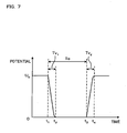
- FIG. 7 Shown in Fig. 7 is one example of a change in potential in the individual electrode 35 to which a voltage pulse signal for causing an ink droplet to be ejected from the ejection opening 8a has been supplied.
- a waveform of the voltage pulse signal to be supplied to the individual electrode 35 is a simple rectangular wave where each of a rising edge and a trailing edge has an angle of 90 degrees.
- the waveform has a pulse width To and indicates a high level potential U 0 and a low level potential 0 as shown in Fig. 7 .
- time t1 the supply of the voltage pulse signal to the individual electrode 35 is started.
- the time t1 is adjusted in accordance with a timing at which the ink is ejected from the ejection opening 8a.
- the potential of the individual electrode 35 is maintained to U 0 (#0).
- time period from time t2 to time t3 the individual electrode 35 is maintained to the ground potential.
- a time period from the time t1 to the time t2 is a transition period during which the potential of the individual electrode 35 changes from U 0 to the ground potential.
- a time period from the time t3 to the time 4 is a transition period during which the potential of the individual electrode 35 changes from the ground potential to U 0 .
- the piezoelectric actuator 50 since the piezoelectric actuator 50 has the constitution similar to that of a condenser, the above-described transition periods are generated when the potential of the individual electrode 35 changes.
- a length Tv 1 of the transition period from the time t1 to time t2 and a length Tv 2 of the transition period from the time t3 to the time t4 depend on the size and the shape of the individual electrode 35, a distance between the individual electrode 35 and the common electrode 34, a dielectric constant of the piezoelectric layer 41, and the waveform of the voltage pulse signal supplied to the individual electrode 35.
- the size and the shape of the individual electrode 35, the distance between the individual electrode 35 and the common electrode 34, and the dielectric constant of the piezoelectric layer 41 are set to predetermined values, and the waveform of the voltage pulse signal applied to the individual electrode 35 is preliminary adjusted so that 0.5 Td ⁇ Tv 1 ⁇ 0.6 Td and 0.33 Td ⁇ Tv 2 ⁇ 0.44 Td are satisfied when a characteristic vibration period in ink filled in the first ink passage 33 is set to Td.
- the waveform of the voltage pulse signal is adjusted so that a length of a time period from the time t1 to the time t3, i.e., the pulse with To, is in a range enabling the desired ink to be ejected from the ejection opening 8a of the nozzle 8 corresponding to the individual electrode 35.
- Such voltage pulse signal is supplied to the individual electrode 35, so that a prominent reduction in ink ejection speed is prevented and thus the ink ejection is maintained at the most stable state.
- the actuator unit 21 in the embodiment shown in Fig. 5 only the uppermost piezoelectric layer 41 is polarized in a direction toward the common electrode 34 from the individual electrode 35. Therefore, by setting the potential of the individual electrode 35 to a value different from that of the common electrode 34, and by applying to the piezoelectric layer 41 an electric field in a direction same as the polarization direction, a portion to which the electric field was applied, i.e., an active portion, starts to extend in a thickness direction, i.e., in the lamination direction. At the same time, the active portion starts to shrink in a direction perpendicular to the lamination direction, i.e., in a surface direction of the layer 41. In contrast, the rest of three piezoelectric layers 42 to 44 do not spontaneously deform upon application of the electric field since they are not polarized.
- the piezoelectric layer 41 and the piezoelectric layers 42 to 44 exhibit different strains, so that the piezoelectric actuators 50 as a whole are deformed to form a projection toward the pressure chambers 10, i.e., present a unimorph deformation.
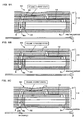
- Figs. 8A to 8C are diagrams generally showing a change with time of the piezoelectric actuator 50 when the potential of the individual electrode changes due to the supply of the voltage pulse signal as shown in Fig. 7 .
- Shown in Fig. 8A is a state of the piezoelectric actuator 50 during the time period till the time t1 shown in Fig. 7 .
- the potential of the individual electrode 35 is U 0 . Therefore, the piezoelectric actuator 50 is projected toward the pressure chamber 10 due to the above-described unimorph deformation.
- a volume of the pressure chamber 10 during this time period is V1. This state will be referred to as a first state of the pressure chamber 10.
- Shown in Fig. 8B is a state of the piezoelectric actuator 50 during the time period from the time t2 to the time t3 shown in Fig. 7 .
- the potential of the individual electrode 35 is the ground potential. Therefore, the electric field that has been applied to the active portion of the piezoelectric layer 41 is released so that the unimorph deformation of the piezoelectric actuator 50 is released.
- a volume V2 of the pressure chamber 10 during this time period is larger than the volume V1 of the pressure chamber 10 shown in Fig. 8A .
- This state will be referred to as a second state of the pressure chamber 10.
- the ink is drawn into the pressure chamber 10 from the sub-manifold channel 5a.
- Shown in Fig. 8C is a state of the piezoelectric actuator 50 during the time period after the time t4 shown in Fig. 7 .
- the potential of the individual electrode 35 is U 0 . Therefore, the piezoelectric actuator 50 is returned to the first state. Since the piezoelectric actuator 50 changes the pressure chamber 10 from the second state to the first state, pressure is applied to the ink in the pressure chamber 10. Thus, an ink droplet is ejected from the ejection opening 8a at the tip of the nozzle 8.
- the ink droplet lands on a printing surface, i.e., the top face, of the printing paper P to form a dot.
- the volume of the pressure chamber 10 is temporarily increased to generate a negative pressure wave in the ink in the pressure chamber 10 (from Fig. 8A to Fig. 8B ). Then, the pressure wave is reflected at the end of an ink passage inside the passage unit 4 to be returned as a positive pressure wave proceeding to the nozzle 8. At a timing when the positive pressure wave reaches to the pressure chamber 10, the volume of the pressure chamber 10 is reduced again (from Fig. 8B to Fig. 8C ). This is the so-called fill before fire method.
- the pulse width To (see Fig. 7 ) of the voltage pulse signal is adjusted to AL.
- AL means a length of time required for a pressure wave generated in the pressure chamber 10 to transmit from the end of the aperture 12 near the pressure chamber 10 to the ejection opening 8a at the tip of the nozzle 8.
- the pulse width To is adjusted to AL, the positive pressure wave reflected as described above and the positive pressure wave generated due to the deformation of the piezoelectric actuator 50 superimpose on each other to thereby apply stronger pressure to ink.
- the driving voltage of the piezoelectric actuator 50 for ejecting the same amount of ink can be lower. Consequently, the fill before fire method is advantageous from the stand points of high collection in the pressure chamber 10, compact size of the inkjet head 2, and a running cost for driving the inkjet head 2.
- the timing at which the potential of the individual electrode 35 changes substantially coincides with the timing at which the piezoelectric actuator 50 deforms. Therefore, in this specification, it is assumed that the timing at which the potential of the individual electrode 35 changes coincides with the timing at which the piezoelectric actuator 50 deforms.
- the volume of the pressure chamber 10 starts to diminish at the same time when the potential of the individual electrode 35 starts to diminish at the time t1. Then, the volume of the pressure chamber 10 becomes the minimum value at the same time when the potential of the individual electrode 35 becomes the ground potential at the time t2. Even if the timing at which the potential of the individual electrode 35 changes was different from the timing at which the actuator 50 deforms, this invention can be applied in view of the difference in advance.
- the piezoelectric actuator 50 shown in Fig. 5 is used as a pressure actuator for applying pressure to ink.
- the piezoelectric actuator 50 has the individual electrode 35 and the common electrode 34, and the common electrode 34 is continuously maintained to the ground potential.
- the piezoelectric actuator 50 deforms due to the piezoelectric strain to change the volume of the pressure chamber 10.
- the pressure wave generated due to the volume change of the pressure chamber 10 reaches to the nozzle 8, the meniscus of the ink formed in the nozzle 8 is deformed, so that a part of the ink forming the meniscus is ejected as an ink droplet.
- ink is supplied from the upstream of the pressure chamber 10, for example, from the sub-manifold channel 5a shown in Fig. 4 , in an amount equal to that previously ejected.
- ink is ejected from the ejection opening 8a by the fill before fire method performed by deforming the piezoelectric actuator 50 by supplying a predetermined voltage pulse signal to the individual electrode 35.
- Fig. 9 is a graph showing the speed of ink ejected by the voltage pulse signal varied in pulse width To (see Fig. 7 ).
- the inventors have confirmed that a curve C2 having several local maximal values and local minimal values when the pulse width To is other than AL is obtained in actuality.
- the inventors have considered that the function of the ejection speed with respect to the pulse width To takes the local maximal or minimal value when To is other than AL as in the curve C2 due to the following causes. That is, it is considered that the ink ejection speed has the characteristics indicated by the curve C1 due to the pressure wave in the ink filled in the individual ink passage 32 of the head 2. It has also been considered that the characteristics of the curve C2 appear due to vibration generated in a local range different from the range in which the pressure wave imparting the characteristics of the curve C1 transmits, more specifically, due to characteristic vibration of ink filled in the first ink passage 33 described above (see Fig. 4 ).
- the characteristic vibration is considered to occur as described below.
- the pressure wave arises in the ink in the pressure chamber 10 due to the deformation of the piezoelectric actuator 50, the pressure wave transmits in a direction upstream of the pressure chamber 10, i.e., in a direction oriented to the sub-manifold channel 5a, as well as to a downstream direction, i.e., in a direction oriented to the nozzle 8 (see Fig. 4 ).
- the volume of the pressure chamber 10 is temporarily increased and then returned to the original volume after the time period corresponding to the pulse width To, so that ink is ejected from the ejection opening 8a as described above.
- the negative pressure wave (hereinafter referred to as first pressure wave) occurs in the ink in the pressure chamber 10, and, in subsequently reducing the volume, the positive pressure wave (hereinafter referred to as second pressure wave) occurs in the ink in the pressure chamber 10.
- a part of the pressure wave transmits to the first ink passage 33 at the downstream as described above. Therefore, the first pressure wave transmitted to the first ink passage 33, for example, is reflected at one end of the first ink passage 33, i.e., at the boundary between the pressure chamber 10 and the first ink passage 33, or near the nozzle 8. Due to the reflected wave, the characteristic vibration arises in ink filled in the first ink passage 33.
- a part of the first pressure wave transmits toward the sub-manifold channel 5a.
- the part of the first pressure wave is reflected at the end of the aperture 12 near the pressure chamber 10 and then transmitted, as a pressure wave of which the polarity is reversed, toward the pressure chamber 10 and the first ink passage 33 to proceed to the ejection opening 8a. That is, the part of the first pressure wave returns to the pressure chamber 10 as a positive pressure wave (hereinafter referred to as third pressure wave) after the reversal of pressure when reflected at the end of the aperture 12.
- third pressure wave a positive pressure wave
- Ink is ejected from the ejection opening 8a when the synthetic wave produced by the overlapping of the second pressure wave with the third pressure wave reaches to the nozzle 8 as a proceeding wave.
- a part of the second and the third pressure waves is overlapped with the characteristic vibration wave generated in the first ink passage 33 by the part of the first pressure wave. Therefore, when the second and the third pressure waves reach to the nozzle 8 as the proceeding wave, not only a vibration produced by the proceeding wave but also a synthetic vibration produced by the overlapping of the vibration generated by the part of the second and the third pressure waves with the vibration generated by the first pressure wave is observed in the vicinity of the nozzle 8.
- the second and the third pressure waves that are overlapped with each other at the timing when the ink ejection speed becomes the local maximal value indicated by the curve C1 in Fig. 9 reach the nozzle 8.
- the case wherein the state of the pressure chamber 10 starts to be changed from the second state to the first state at any of the timings till the pressure inside the pressure chamber 10 becomes the maximum due to the third pressure wave corresponds to the case of To ⁇ AL.
- the synthetic wave of the second and the third pressure waves reaches to the vicinity of the nozzle 8 when the pressure of the ink in the vicinity of the nozzle 8 becomes the maximum value caused by the synthetic vibration due to the first to the third pressure waves. Consequently, in the vicinity of the nozzle 8, the positive pressure synthetic wave transmitted from the pressure chamber 10 is overlapped with the maximum positive pressure caused by the synthetic vibration, so that the ejection speed becomes the local maximal value as shown in Fig. 9 .
- Figs. 10A to 10C are diagrams showing contents of the simulation.
- the individual ink passage 32 shown in Fig. 4 i.e., the passage extending from the outlet of the sub-manifold channel 5a to the ejection opening 8a at the tip of the nozzle 8 via the aperture 12 and the pressure chamber 10, is used as a circuit obtained by acoustically subjecting the passage to equivalent conversion (see Fig. 10A ), and acoustic analysis on the equivalent circuit was performed.
- the aperture 12 corresponds to a coil 212a and a resistance 212b
- the piezoelectric actuator 50 corresponds to a condenser 250
- the pressure chamber 10 corresponds to a condenser 210.
- the first ink passage 33 corresponds to a fluid analysis unit 233 in this circuit.
- the fluid analysis unit 233 is not considered as a component of the circuit, such as the condenser and the resistance, but is to be subjected to numerical analysis by fluid analysis described later.
- the thickness of the piezoelectric actuator 50 For the acoustic analysis of this simulation, the thickness of the piezoelectric actuator 50, an area and a depth of the pressure chamber 10 with respect to a thickness direction of the piezoelectric actuator 50, a width, a length, and a depth of the aperture 12 with respect to the thickness direction, and the like are used.
- Compliance (acoustic capacity) of the piezoelectric actuator 50 i.e., a capacity of the condenser 250 in the equivalent circuit, and a pressure constant are preliminary determined from the construction of the piezoelectric actuator 50 and the like by employing the finite element method.
- the piezoelectric constant is determined by employing the resonance method for measuring impedance of a piezoelectric element.
- FIG. 10B Shown in Fig. 10B is a structure of the first ink passage 33 in the fluid analysis unit 233. Shown in Fig. 10C is a structure of the nozzle 8 in the first ink passage 33 shown in Fig. 10B .
- a range corresponding lengths L1, L2, L3 and L4 indicates the first ink passage 33 excluding the nozzle 8.
- the left end of Fig. 10B is a part connected to the pressure chamber 10.
- Inner diameters D1, D2, D3 and D4 and the lengths L1 to L4 of the first ink passage 33 used in this fluid analysis are as shown in Table 1.
- a diameter D5 of the tip of the nozzle 8, i.e., of the ejection opening 8a, and other elements L5, L6, and ⁇ are as shown in Table 2.
- the fluid analysis in the fluid analysis unit 233 was performed by using the structure of the first ink passage 33 described above and by employing the pseudo compression method which is fluid analysis formulated by pseudo compressibility, i.e., by employing a method of determining speed and pressure by using a simultaneous expressions consisting of a continuity expression to which "A" representing time change of density is added in a pseudo manner and the Navier-Stokes expression.
- the compliance (acoustic capacity) of the pressure chamber 10, i.e., a capacity of the condenser 250 in the equivalent circuit, was determined from a relational expression C W*Ev.
- C represents the compliance
- W represents the volume of the pressure chamber 10
- Ev represents a volumetric elastic modulus of the ink.
- m represents the inertance
- ⁇ represents a density of the ink
- A represents an area of a section with respect to a direction perpendicular to the thickness direction in the aperture 12
- 1 represents a length of the aperture 12 with respect to a horizontal direction of Fig. 4 .
- the aperture 12 has the rectangular shape of which the sides with respect to the direction perpendicular to the thickness direction have the lengths 2a and 2b.
- the amount of ink flowing through the aperture 12 is represented by using the following Expression 1.
- the resistance value R is calculated by using this expression and Expression 1.
- 1 represents a length of the aperture 12 as described above
- ⁇ represents the viscosity of ink.
- a volumetric speed of ink passing through the fluid analysis unit 233 is determined.
- a pressure P corresponding to the voltage applied between the individual electrode 35 and the common electrode 34 is to be added by a pressure source 299 in the circuit.
- the volumetric speed of the ink flowing through the circuit was obtained by numerical analysis, based on the pressure P, the acoustic capacity, the inertance, the resistance value, and an analysis result in the fluid analysis unit 233 separately obtained. Results of the numerical analysis are shown in Table 3.
- Td represents a characteristic vibration period of ink filled in the first ink passage 33
- Td and Tc depend on the shape of the individual ink passage 32. Since the individual ink passages 32 used in the simulations had an identical shape, Td and Tc are constant.
- Tv 1 indicates a time required for the potential of the individual electrode 35 to transitionally change from U 0 to the ground potential (see Fig. 7 ). The waveform of the voltage pulse signal was changed in order to vary Tv 1 .
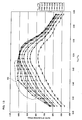
- Fig. 11 is a graph showing the results of the numerical analysis shown in Table 3.
- the horizontal axis represents To/Tc, and the vertical axis represents the ratio of the ejection speed.
- Each of the curves shows a result per parameter Tv 1 /Td.
- Tv 1 /Td is less than 0.33, i.e., the ratio of Tv 1 to Td is less than 33%
- the extreme value corresponds to the extreme value indicated in the curve C2 of Fig. 9 .
- the horizontal axis in Fig. 12A indicates a ratio of Tv 1 to Tc
- the horizontal axis in Fig. 12B indicates a ratio of Tv 1 to Td.
- a reduction in ejection speed is prominent particularly when the ratio of Tv 1 to Tc exceeds 12%.
- the passage unit 4 has the sub-manifold channels 5a for supplying ink to the pressure chambers 10 and the second ink passage extending from the outlets of the sub-manifold channels 5a to the inlets of the pressure chambers 10 and that the controller 100 controls the piezoelectric actuator 50 so as to keep Tv 1 to 12% or less of Tc. Further, it is more preferable to control the piezoelectric actuator 50 so as to keep Tv 1 to 67% or less of Td. In such case, the speed of the ink ejected from the ejection opening 8a is ensured satisfactorily in view of the analysis. This is because the pressurizing efficiency is improved when pressure is applied satisfactorily rapidly to ink in the pressure chamber 10 by the piezoelectric actuator 50 due to Tv 1 that is reduced to the satisfactory value.
- the ratio of the ejection speed is reduced from 100% when the ratio of Tv 1 to Tc exceeds 6.4% or the ratio of Tv 1 to Td exceeds 42%. Therefore, in order to keep the ratio of the ejection speed to about 100%, it is preferable to keep the ratio of Tv 1 to Tc to 6.4% or less and to keep the ratio of Tv 1 to Td to 42% or less. With such ratios, it is possible to keep the ejection speed to the maximum value.
- Table 4 shows results of the numerical analysis in the simulation, the results being different from those shown in Table 3.
- Fig. 13 is a graph showing the results of the numerical analysis shown in Table 4.
- the horizontal axis represents To/Tc, and the vertical axis represents the ratio of the ejection speed.
- Each of the curves shows a result per parameter Tv 2 /Td.
- Tv 2 /Td is less than 0.33, i.e., the ratio of Tv 2 to Td is less than 33%
- the piezoelectric actuator 50 it is preferable to control the piezoelectric actuator 50 so as to keep the Tv 2 to 33% or more of Td.
- the problem of unsatisfactory reproduction of images due to the occurrence of noise or variation in ink ejection speed is suppressed, as the extreme value is seldom or never appears when the ratio of Tv 2 to Td is 33% or more in the above analysis results as shown in Fig. 13 .
- Such effect is achieved since the change in pressure applied by the piezoelectric actuator 50 to ink in the pressure chamber 10 is moderated due to the satisfactory increase in Tv 2 .
- a pressure wave that generates the characteristic vibration hardly arises in ink filled in the first ink passage 33, so that the excitation of the characteristic vibration is suppressed.
- Tv 2 0.9Tv 1 100.61% 99.46% 100.28% 99.97% 98.69% 95.93% 92.85% 91.21% 83.71%
- Tv 2 Tv 1 100.61% 99.39% 100.00% 99.35% 96.57% 94.19% 89.85% 87.01% 78.07%
- Tv 2 1.1Tv 1 100.61% 99.28% 99.60% 98.52% 95.19% 92.12% 86.98% 80.72% 72.25%
- Fig. 14 is a graph showing the results of the numerical analysis shown in Table 5.
- the horizontal axis represents the ratio of Tv 1 to Td, and the vertical axis represents the ratio of the ejection speed.
- a relationship "the ejection speed of the curve 93 > the ejection speed of the curve 94 > the ejection speed of the curve 95" is established in almost all the range of Tv 1 /Td as shown in Fig. 14 .
- Tv 1 > Tv 2 it is preferable that the relationship of Tv 1 > Tv 2 is established. With such relationship, the ink ejection speed is increased irrelevant from the value of Tv 1 as compared to the case where Tv 1 ⁇ Tv 2 , and the ink ejection speed suitable for printing is ensured in the wide range of Tv 1 /Td.
- Table 6 Shown in Table 6 are ratios of speed of the ink ejected from the ejection opening 8a in the case where Tv 1 and Tv 2 are varied.
- the ejection speed is maintained to 98% or more of the reference value when Tv 2 /Td ⁇ 0.44.
- Tv 1 /Td ⁇ 0.60 an extreme reduction in ejection speed is prevented simultaneously with maintaining the ink ejection at the most stable state.
- the piezoelectric actuator 50 it is preferable to control the piezoelectric actuator 50 in such a manner that the ratio of Tv 1 to Td becomes 50% to 60% and the ratio of Tv 2 to Td becomes 33% to 44%. With such control, an extreme reduction in ejection speed is prevented simultaneously with maintaining the ink ejection at the most stable state.
- the pulse with To may be a value other than AL.
- the pulse with To may be a value other than AL.
- the ratio of change of the ejection speed with respect to the pulse width To is larger than that of the case of To/Tc ⁇ 0.5 regardless of the value of Tv 1 or Tv 2 .
- the change ratio is gradual as compared to the other ranges of To/Tc.
- the ejection speed change ratio with respect to the pulse width To is small, i.e., the influence of the change in the pulse width To upon the ejection speed is reduced.
- the ejection speed is maintained to 80% or more of the reference value and the freedom of the ejection speed with respect to the pulse width To is increased by maintaining To/Tc to the range of 0.4 to 0.5. That is, the vibration of ink in the first ink passage 33 acts effectively on the ink ejection in the wide range of the pulse width To, so as to avoid an extreme change or reduction in ejection speed and to maintain the ink ejection at the most stable state.
- the waveform of the voltage pulse signal is not limited to the rectangular wave insofar as the above conditions are satisfied when a voltage pulse signal corresponding to the waveform is applied to the individual electrode 35 and can be a non-rectangular wave wherein each of a trailing edge and a rising edge has an angle larger than 90 degrees as in the potential change curve of the individual electrode 35 shown in Fig. 7 .
- Tv 1 and/or Tv 2 are not limited to the adjustment of the waveform of the voltage pulse signal supplied to the individual electrode 35.
- Tv 1 and/or Tv 2 may be set to the above numerical ranges by adjusting any one of the size and the shape of the individual electrode 35, the distance between the individual electrode 35 and the common electrode 34, and the dielectric constant of the piezoelectric layer 41.
- Wave data indicating various types of basic waveforms with which Tv 1 , Tv 2 , and the like satisfy the above-described conditions such as Tv 1 ⁇ 0.33 Td or Tv 1 ⁇ 0.12 Tc when the voltage pulse signal is supplied to the individual electrode 35 may preliminary be stored in the wave data memory 103, so that the print controller 101 selects one of the basic waveforms indicated by the wave data stored in the wave data memory 103 to supply a voltage pulse signal corresponding to the selected basic waveform to the individual electrode 35.
- the problem according to this invention is raised when the characteristic vibration of the pressure generated in ink filled in the first ink passage 33 overlaps with the pressure wave reflected in the ink passage. Therefore, the problem according to this invention can occur in other components than the passage unit 4 shown in Fig. 4 which has the sub-manifold channel 5a and the individual ink passage 32 including the first ink passage 33, the pressure chamber 10, and the aperture 12. It is also understood that, since the problem according to this invention is raised due to the overlapping of the pressure waves generated in the ink passage as described above, the problem according to this invention is raised irrelevant from the method of pressurizing ink. Therefore, the problem according to this invention can be raised in the cases where ink is pressurized by a pressurizing actuator other than the piezoelectric actuator.
Landscapes
- Particle Formation And Scattering Control In Inkjet Printers (AREA)
Claims (8)
- Kombination von einer Tintenstrahlaufzeichnungsvorrichtung (1) und einer Tinte, wobei die Tintenstrahlaufzeichnungsvorrichtung (1) aufweist:einen Druckbeaufschlagungsaktor (21);eine Kanaleinheit (4), in der eine Druckkammer (10), deren Volumen durch den Druckbeaufschlagungsaktor (21) verändert wird, und eine Ausstoßöffnung (8a) zum Ausstoßen der Tinte ausgebildet sind, wobei die Kanaleinheit (4) einen ersten Tintenkanal (33) aufweist, der sich von einem Auslass der Druckkammer (10) zu der Ausstoßöffnung (8a) erstreckt; undeinen Controller (100), der den Druckbeaufschlagungsaktor (21) derart steuert, dass die Druckkammer (10) von einem ersten Zustand, in dem ein Volumen der Druckkammer (10) V1 ist, in einen zweiten Zustand wechselt, in dem das Volumen V2 ist, das größer als V1 ist, und dann von dem zweiten Zustand in den ersten Zustand zurückkehrt, um zu bewirken, dass die Tinte aus der Ausstoßöffnung (8a) ausgestoßen wird,dadurch gekennzeichnet, dass der Controller (100) den Druckbeaufschlagungsaktor (21) ferner derart steuert, dass eine Zeitlänge Tv1 ab einem Zeitpunkt, zu dem die Druckkammer (10) beginnt, von dem ersten Zustand in den zweiten Zustand zu wechseln, bis einem Zeitpunkt, zu dem die Druckkammer (10) sich in dem zweiten Zustand befindet, 33 % oder mehr von einer charakteristischen Vibrationszeitspanne Td der Tinte, mit der der erste Tintenkanal (33) befüllt ist, erreicht und derart, dass die Zeitlänge Tv1 83 % oder weniger der charakteristischen Vibrationszeitspanne Td erreicht.
- Kombination nach Anspruch 1, dadurch gekennzeichnet, dass die Kanaleinheit (4) ferner eine gemeinsame Tintenkammer (5a) zum Zuführen der Tinte zu der Druckkammer (10) und einen zweiten Tintenkanal aufweist, der sich von einem Auslass der gemeinsamen Tintenkammer (5a) zu einem Einlass der Druckkammer (10) erstreckt; und
der Controller (100) den Druckbeaufschlagungsaktor (21) ferner so steuert, dass die Zeitlänge Tv1 12 % oder weniger von einer charakteristischen Vibrationszeitspanne Tc der Tinte erreicht, mit der ein einzelner Tintenkanal (32) befüllt ist, der aus dem ersten und dem zweiten Tintenkanal und der Druckkammer (10) besteht. - Kombination nach Anspruch 1 oder 2, dadurch gekennzeichnet, dass der Controller (100) den Druckbeaufschlagungsaktor (21) derart steuert, dass die Zeitlänge Tv1 67 % oder weniger der charakteristischen Vibrationszeitspanne Td erreicht.
- Kombination nach einem der Ansprüche 1 bis 3, dadurch gekennzeichnet, dass der Controller (100) den Druckbeaufschlagungsaktor (21) ferner derart steuert, dass eine Zeitlänge Tv2 ab einem Zeitpunkt, zu dem die Druckkammer (10) beginnt, von dem zweiten Zustand in den ersten Zustand zu wechseln, bis zu einem Zeitpunkt, zu dem die Druckkammer (10) in den ersten Zustand zurückkehrt, 33 % oder mehr der charakteristischen Vibrationszeitspanne Td erreicht.
- Kombination nach Anspruch 4, dadurch gekennzeichnet, dass der Controller (100) den Druckbeaufschlagungsaktor (21) ferner derart steuert, dass die Zeitlänge Tv2 geringer wird als die Zeitlänge Tv1.
- Kombination nach Anspruch 5, dadurch gekennzeichnet, dass der Controller den Druckbeaufschlagungsaktor (21) ferner derart steuert, dass die Zeitlänge Tv1 50 % bis 60 % der charakteristischen Vibrationszeitspanne Td erreicht und dass die Zeitlänge Tv2 33 % bis 44 % der charakteristischen Vibrationszeitspanne erreicht.
- Kombination nach einem der Ansprüche 1 bis 6, dadurch gekennzeichnet, dass eine Wellenform eines Signals, das dem Druckbeaufschlagungsaktor (21) zugeführt wird, um das Volumen der Druckkammer (10) zu verändern, eine einfache Rechteckwelle ist.
- Verfahren zum Steuern einer Kombination von einer Tintenstrahlaufzeichnungsvorrichtung (1) und einer Tinte, wobei die Tintenstrahlaufzeichnungsvorrichtung (1) aufweist: einen Druckbeaufschlagungsaktor (21); und eine Kanaleinheit (4), in der eine Druckkammer (10), deren Volumen durch den Druckbeaufschlagungsaktor (21) verändert wird, und eine Ausstoßöffnung (8a) zum Ausstoßen der Tinte ausgebildet sind, wobei die Kanaleinheit (4) einen ersten Tintenkanal (33) aufweist, der sich von einem Auslass der Druckkammer (10) zu der Ausstoßöffnung (8a) erstreckt;
wobei das Verfahren einen Schritt aufweist zum Steuern des Druckbeaufschlagungsaktors (21) derart, dass die Druckkammer (10) von einem ersten Zustand, in dem ein Volumen der Druckkammer (10) V1 ist, in einen zweiten Zustand wechselt, in dem das Volumen V2 ist, das größer als V1 ist, und dann von dem zweiten Zustand in den ersten Zustand wechselt, um zu bewirken, dass die Tinte aus der Ausstoßöffnung (8a) ausgestoßen wird ,
gekennzeichnet durch den Schritt des Steuerns des Druckbeaufschlagungsaktors (21) ferner derart, dass eine Zeitlänge Tv1 ab einem Zeitpunkt, zu dem die Druckkammer (10) beginnt, von dem ersten Zustand in den zweiten Zustand zu
wechseln, bis einem Zeitpunkt, zu dem die Druckkammer (10) sich in dem zweiten Zustand befindet, 33 % oder mehr von einer charakteristischen Vibrationszeitspanne Td der Tinte, mit der der erste Tintenkanal (33) befüllt ist, erreicht und derart, dass die Zeitlänge TV1 83 % oder weniger der charakteristischen Vibrationszeitspanne Td erreicht.
Applications Claiming Priority (1)
| Application Number | Priority Date | Filing Date | Title |
|---|---|---|---|
| JP2005293862 | 2005-10-06 |
Publications (3)
| Publication Number | Publication Date |
|---|---|
| EP1772268A2 EP1772268A2 (de) | 2007-04-11 |
| EP1772268A3 EP1772268A3 (de) | 2008-07-02 |
| EP1772268B1 true EP1772268B1 (de) | 2011-05-04 |
Family
ID=37667333
Family Applications (1)
| Application Number | Title | Priority Date | Filing Date |
|---|---|---|---|
| EP06020961A Active EP1772268B1 (de) | 2005-10-06 | 2006-10-05 | Tintenstrahlaufzeichnungsgerät und dessen Steuerverfahren |
Country Status (4)
| Country | Link |
|---|---|
| US (1) | US7661783B2 (de) |
| EP (1) | EP1772268B1 (de) |
| CN (1) | CN100475537C (de) |
| DE (1) | DE602006021681D1 (de) |
Families Citing this family (2)
| Publication number | Priority date | Publication date | Assignee | Title |
|---|---|---|---|---|
| JP5059336B2 (ja) * | 2006-03-30 | 2012-10-24 | ブラザー工業株式会社 | インクジェット記録装置及びその制御条件の決定方法 |
| CN112903716B (zh) * | 2021-01-21 | 2022-07-08 | 安徽祁鸣春农业科技有限公司 | 一种放置稳定的食品加工用罐底喷码检测机 |
Family Cites Families (15)
| Publication number | Priority date | Publication date | Assignee | Title |
|---|---|---|---|---|
| US6095630A (en) * | 1997-07-02 | 2000-08-01 | Sony Corporation | Ink-jet printer and drive method of recording head for ink-jet printer |
| JP3857805B2 (ja) * | 1997-12-10 | 2006-12-13 | ブラザー工業株式会社 | インク滴噴射方法及びその装置 |
| JP3842886B2 (ja) * | 1997-12-16 | 2006-11-08 | ブラザー工業株式会社 | インク滴噴射方法及びその装置 |
| JP3159188B2 (ja) | 1998-10-20 | 2001-04-23 | 日本電気株式会社 | インクジェット記録ヘッドの駆動方法 |
| US7014294B2 (en) * | 2000-11-30 | 2006-03-21 | Brother Kogyo Kabushiki Kaisha | Ink-jet head and ink-jet printer having ink-jet head |
| JP2003165212A (ja) * | 2001-11-30 | 2003-06-10 | Brother Ind Ltd | インクジェットヘッド |
| US6808254B2 (en) * | 2000-11-30 | 2004-10-26 | Brother Kogyo Kabushiki Kaisha | Ink jet printer head |
| US6953241B2 (en) * | 2001-11-30 | 2005-10-11 | Brother Kogyo Kabushiki Kaisha | Ink-jet head having passage unit and actuator units attached to the passage unit, and ink-jet printer having the ink-jet head |
| US6984027B2 (en) * | 2001-11-30 | 2006-01-10 | Brother Kogyo Kabushiki Kaisha | Ink-jet head and ink-jet printer having ink-jet head |
| CN2752050Y (zh) * | 2002-02-18 | 2006-01-18 | 兄弟工业株式会社 | 喷墨打印头以及具有该喷墨打印头的喷墨打印机 |
| JP2003305852A (ja) | 2002-02-18 | 2003-10-28 | Brother Ind Ltd | インクジェットヘッド及びこれを有するインクジェットプリンタ |
| JP4247043B2 (ja) | 2002-06-28 | 2009-04-02 | 東芝テック株式会社 | インクジェットヘッドの駆動装置 |
| JP2004114362A (ja) | 2002-09-24 | 2004-04-15 | Brother Ind Ltd | インクジェットヘッド |
| US7150517B2 (en) * | 2003-03-28 | 2006-12-19 | Kyocera Corporation | Method for driving piezoelectric ink jet head |
| JP2006150817A (ja) | 2004-11-30 | 2006-06-15 | Brother Ind Ltd | インクジェット記録装置 |
-
2006
- 2006-10-05 DE DE602006021681T patent/DE602006021681D1/de active Active
- 2006-10-05 EP EP06020961A patent/EP1772268B1/de active Active
- 2006-10-05 US US11/538,832 patent/US7661783B2/en active Active
- 2006-10-08 CN CNB2006101421179A patent/CN100475537C/zh active Active
Also Published As
| Publication number | Publication date |
|---|---|
| EP1772268A2 (de) | 2007-04-11 |
| US7661783B2 (en) | 2010-02-16 |
| US20070081050A1 (en) | 2007-04-12 |
| DE602006021681D1 (de) | 2011-06-16 |
| CN100475537C (zh) | 2009-04-08 |
| EP1772268A3 (de) | 2008-07-02 |
| CN1944054A (zh) | 2007-04-11 |
Similar Documents
| Publication | Publication Date | Title |
|---|---|---|
| US8087760B2 (en) | Liquid ejection head and driving method thereof | |
| EP1403047B1 (de) | Tintenstrahldrucker und Aktuatorsteuerung und Methode zur Aktuatorsteuerung für die Verwendung in einem Tintenstrahldrucker | |
| EP1839868B1 (de) | Tintenstrahlkopf | |
| EP1832425B1 (de) | Tintenstrahlkopf | |
| EP1839865B1 (de) | Tintenstrahlaufzeichnungsgerät und Verfahren zur Bestimmung der Steuerbedingungen in dem Gerät | |
| US7628462B2 (en) | Droplet discharge device and method of driving the same | |
| US20040090476A1 (en) | Apparatus for ejecting droplets, actuator controller used in the apparatus, and method for controlling the actuator | |
| EP1772268B1 (de) | Tintenstrahlaufzeichnungsgerät und dessen Steuerverfahren | |
| JP4588618B2 (ja) | インクジェット記録装置 | |
| US7780272B2 (en) | Inkjet printer | |
| JP2007125881A (ja) | インクジェット記録装置及びその制御方法 | |
| JP2004136666A (ja) | インクジェット記録装置、これに用いられるアクチュエータ制御装置、および、アクチュエータ制御方法 |
Legal Events
| Date | Code | Title | Description |
|---|---|---|---|
| PUAI | Public reference made under article 153(3) epc to a published international application that has entered the european phase |
Free format text: ORIGINAL CODE: 0009012 |
|
| AK | Designated contracting states |
Kind code of ref document: A2 Designated state(s): AT BE BG CH CY CZ DE DK EE ES FI FR GB GR HU IE IS IT LI LT LU LV MC NL PL PT RO SE SI SK TR |
|
| AX | Request for extension of the european patent |
Extension state: AL BA HR MK YU |
|
| PUAL | Search report despatched |
Free format text: ORIGINAL CODE: 0009013 |
|
| AK | Designated contracting states |
Kind code of ref document: A3 Designated state(s): AT BE BG CH CY CZ DE DK EE ES FI FR GB GR HU IE IS IT LI LT LU LV MC NL PL PT RO SE SI SK TR |
|
| AX | Request for extension of the european patent |
Extension state: AL BA HR MK RS |
|
| 17P | Request for examination filed |
Effective date: 20081229 |
|
| AKX | Designation fees paid |
Designated state(s): DE FR GB |
|
| 17Q | First examination report despatched |
Effective date: 20091016 |
|
| GRAP | Despatch of communication of intention to grant a patent |
Free format text: ORIGINAL CODE: EPIDOSNIGR1 |
|
| GRAS | Grant fee paid |
Free format text: ORIGINAL CODE: EPIDOSNIGR3 |
|
| GRAA | (expected) grant |
Free format text: ORIGINAL CODE: 0009210 |
|
| AK | Designated contracting states |
Kind code of ref document: B1 Designated state(s): DE FR GB |
|
| REG | Reference to a national code |
Ref country code: GB Ref legal event code: FG4D |
|
| REF | Corresponds to: |
Ref document number: 602006021681 Country of ref document: DE Date of ref document: 20110616 Kind code of ref document: P |
|
| REG | Reference to a national code |
Ref country code: DE Ref legal event code: R096 Ref document number: 602006021681 Country of ref document: DE Effective date: 20110616 |
|
| PLBE | No opposition filed within time limit |
Free format text: ORIGINAL CODE: 0009261 |
|
| STAA | Information on the status of an ep patent application or granted ep patent |
Free format text: STATUS: NO OPPOSITION FILED WITHIN TIME LIMIT |
|
| 26N | No opposition filed |
Effective date: 20120207 |
|
| REG | Reference to a national code |
Ref country code: DE Ref legal event code: R097 Ref document number: 602006021681 Country of ref document: DE Effective date: 20120207 |
|
| REG | Reference to a national code |
Ref country code: FR Ref legal event code: PLFP Year of fee payment: 11 |
|
| REG | Reference to a national code |
Ref country code: FR Ref legal event code: PLFP Year of fee payment: 12 |
|
| REG | Reference to a national code |
Ref country code: FR Ref legal event code: PLFP Year of fee payment: 13 |
|
| P01 | Opt-out of the competence of the unified patent court (upc) registered |
Effective date: 20230505 |
|
| PGFP | Annual fee paid to national office [announced via postgrant information from national office to epo] |
Ref country code: GB Payment date: 20240829 Year of fee payment: 19 |
|
| PGFP | Annual fee paid to national office [announced via postgrant information from national office to epo] |
Ref country code: FR Payment date: 20240909 Year of fee payment: 19 |
|
| PGFP | Annual fee paid to national office [announced via postgrant information from national office to epo] |
Ref country code: DE Payment date: 20240828 Year of fee payment: 19 |