EP1772593A2 - Doppelschicht-Schaufelspitzekappe - Google Patents
Doppelschicht-Schaufelspitzekappe Download PDFInfo
- Publication number
- EP1772593A2 EP1772593A2 EP06255037A EP06255037A EP1772593A2 EP 1772593 A2 EP1772593 A2 EP 1772593A2 EP 06255037 A EP06255037 A EP 06255037A EP 06255037 A EP06255037 A EP 06255037A EP 1772593 A2 EP1772593 A2 EP 1772593A2
- Authority
- EP
- European Patent Office
- Prior art keywords
- cap
- shield
- tip cap
- tip
- high strength
- Prior art date
- Legal status (The legal status is an assumption and is not a legal conclusion. Google has not performed a legal analysis and makes no representation as to the accuracy of the status listed.)
- Granted
Links
Images

Classifications
-
- F—MECHANICAL ENGINEERING; LIGHTING; HEATING; WEAPONS; BLASTING
- F01—MACHINES OR ENGINES IN GENERAL; ENGINE PLANTS IN GENERAL; STEAM ENGINES
- F01D—NON-POSITIVE DISPLACEMENT MACHINES OR ENGINES, e.g. STEAM TURBINES
- F01D5/00—Blades; Blade-carrying members; Heating, heat-insulating, cooling or antivibration means on the blades or the members
- F01D5/12—Blades
- F01D5/14—Form or construction
- F01D5/20—Specially-shaped blade tips to seal space between tips and stator
-
- F—MECHANICAL ENGINEERING; LIGHTING; HEATING; WEAPONS; BLASTING
- F05—INDEXING SCHEMES RELATING TO ENGINES OR PUMPS IN VARIOUS SUBCLASSES OF CLASSES F01-F04
- F05D—INDEXING SCHEME FOR ASPECTS RELATING TO NON-POSITIVE-DISPLACEMENT MACHINES OR ENGINES, GAS-TURBINES OR JET-PROPULSION PLANTS
- F05D2230/00—Manufacture
- F05D2230/30—Manufacture with deposition of material
-
- F—MECHANICAL ENGINEERING; LIGHTING; HEATING; WEAPONS; BLASTING
- F05—INDEXING SCHEMES RELATING TO ENGINES OR PUMPS IN VARIOUS SUBCLASSES OF CLASSES F01-F04
- F05D—INDEXING SCHEME FOR ASPECTS RELATING TO NON-POSITIVE-DISPLACEMENT MACHINES OR ENGINES, GAS-TURBINES OR JET-PROPULSION PLANTS
- F05D2230/00—Manufacture
- F05D2230/90—Coating; Surface treatment
-
- F—MECHANICAL ENGINEERING; LIGHTING; HEATING; WEAPONS; BLASTING
- F05—INDEXING SCHEMES RELATING TO ENGINES OR PUMPS IN VARIOUS SUBCLASSES OF CLASSES F01-F04
- F05D—INDEXING SCHEME FOR ASPECTS RELATING TO NON-POSITIVE-DISPLACEMENT MACHINES OR ENGINES, GAS-TURBINES OR JET-PROPULSION PLANTS
- F05D2260/00—Function
- F05D2260/95—Preventing corrosion
Definitions
- the present invention relates generally to a turbine engine and more particularly relates to a bi-layer tip cap for a turbine bucket.
- a turbine stage includes a row of turbine buckets extending outwardly from a supporting rotor disc.
- Each turbine bucket includes an airfoil over which the combustion gases flow.
- the airfoils are generally hollow and may be provided with air bled from the compressor for use as a coolant during operation.
- Each turbine bucket includes a blade body and a tip cap. Due to the environment in which the tip cap operates, the tip cap should be oxidant resistant. The tip cap also is prone to bulging due to creep. Most alloys with sufficient creep strength do not have sufficient resistance to oxidation. Most alloys with adequate oxidation resistance do not have sufficient creep strength. Those alloys that do have adequate properties for both creep and oxidation generally are not available except as custom cast billets. Such custom billets then have to be worked at great expense to form a finished product. Other alternatives include the use of an aluminized coating to the underside of the tip cap.
- a suitable material that provides both adequate oxidation resistance and sufficient creep strength.
- the material should be reasonable in terms of costs and workability.
- the present application thus describes a tip cap for use in a turbine bucket.
- the tip cap may include a shield of an oxidant resistant material and a cap positioned within the shield of a high strength material.
- the oxidant resistant material may be a nickel-based alloy or a cobalt-based alloy.
- the shield may have a thickness of about 0.001 to about 0.030 inches (about 0.025 to about 0.762 millimeters).
- the high strength material may be a nickel-based alloy or a cobalt-based alloy. Specifically, the high strength material may include a precipitation-strengthened, creep resistant super alloy.
- the cap may have a thickness of about 0.030 to 0.120 inches (about 0.762 to about 3 millimeters).
- the shield may have a cup shape and the cap fits within the shield.
- the shield also may be a flat plate and cap may be attached to the shield.
- the shield may be a powder deposited on the cap.
- the shield may be attached to the cap via welding, brazing, or mechanical attachment.
- the present application further describes a turbine bucket.
- the turbine bucket may include an airfoil and a tip cap positioned within the airfoil.
- the tip cap may include an oxidant resistant shield and a high strength cap.
- the oxidant resistant shield may include a nickel-based alloy or a cobalt-based alloy.
- the oxidant resistant shield may have a thickness of about 0.001 to about 0.030 inches (about 0.025 to about 0.762 millimeters).
- the high strength cap may include a nickel-based alloy or a cobalt-based alloy.
- the high strength cap may include a thickness of about 0.030 to 0.120 inches (about 0.762 to about 3 millimeters).
- the high strength cap may include a precipitation-strengthened, creep resistant super alloy.
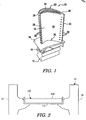
- Fig. 1 depicts an example of a turbine bucket 10.
- the turbine bucket 10 may include a conventional dovetail 12.
- the dovetail 12 attaches to a conventional rotor disc (not shown).
- a blade shank 14 extends upwardly from the dovetail 12 and terminates in a platform 16 that projects outwardly from and surrounds the shank 14.
- a hollow airfoil 18 extends outwardly from the platform 16.
- the airfoil 18 has a root 20 at the junction with the platform 16 and a tip 22 at its outer end.
- the airfoil 18 has a concave pressure sidewall 24 and a convex suction sidewall 26 joined together at a leading edge 28 and a trailing edge 30.
- the airfoil 18 may include a number of trailing edge cooling holes 32 and a number of leading edge cooling holes 33.
- a tip cap 34 may close off the tip 22 of the airfoil 18.
- a squealer tip 36 may extend outwardly from the tip cap 34.
- the airfoil 18 may take any configuration suitable for extracting energy from the hot gas stream and causing rotation of the rotor disc.
- the airfoil 18 described herein is for the purpose of example only. The present application is not intended to be limited to this airfoil embodiment.
- the airfoil 18 may be used in a stage one bucket of a turbine manufactured by General Electric Corporation of Schenectady, New York or in similar types of devices.
- Fig. 2 shows a tip cap 100 as is described herein. As is shown, the tip cap 100 is positioned within the tip 22 of the airfoil 18 between the sidewalls 24 and 26.
- the tip cap 100 may be of two-piece construction and may include a shield 110 and a cap 120.
- the shield 110 is an oxidation shield.
- the shield 110 may be made from an oxidant resistant material such as nickel-based alloys or cobalt-based alloys with additives of aluminum, silicon, lanthanum or other oxidation-resistant additives.
- An alloy such as a Haynes 230 alloy may be used.
- the shield 110 may come as a sheet material, a powder, a wire, a plating material, or other types of compositions.
- the shield 110 may be used as a flat plate, as cladding material, or the shield 110 may be formed into a cup. If formed into a cup, the cup may be performed in isolation or be formed around the cap 120.
- the shield may have a thickness of about 0.001 to about 0.030 inches (about 0.025 to about 0.762 millimeters).
- the cap 120 may come as a sheet or as a forged or a cast material.
- the cap 120 may be made from a nickel-based or cobalt-based gamma-prime strengthened alloy.
- a Nimonic 263 alloy material may be used.
- the material has high strength and corrosion resistance and may exhibit good formability.
- Other types of high strength materials or compositions may be used herein.
- high strength materials we mean materials that are strain tolerant. Precipitation-strengthened, creep resistant super alloys are preferred.
- the cap 120 may have a thickness of about 0.030 to 0.120 inches (about 0.762 to about 3 millimeters).
- the cap 120 may be sized to fit within the shield 110 and the bucket tip 22 of the airfoil 18. Any desired size may be used herein.
- the cap 120 may be wire cut, water jet cut, or laser cut.
- the cap 120 also may be cut mechanically via stamping, shearing, or milling. Other types of manufacturing methods may be used herein.
- the shield 110 may be attached to one (1), two (2), three (3), or all four (4) sides of the cap 120.
- the shield 110 and the cap 120 may be assembled together and resistance welded to form a single composite tip cap 100. Other forms of welding or brazing may be used.
- the shield 110 may extend around the edge of the cap 120 to form a ductile layer to facilitate crack free welding.
- the tip cap 100 may be welded, brazed or mechanically attached to the sidewalls 24, 26 in a conventional manner. Additionally, the shield 110 may be deposited as a filler material or plating material to the cap 120 in a cladding operation.
- the shield 110 is a powder, it may be deposited directly on the cap 120 or it may be weld built by using filler wire, by electroplating, by diffusing a braze perform, or via plasma spray. Other types of manufacturing methods also may be used herein.
- the tip cap 100 thus employs the shield 110 with higher oxidation resistance and somewhat lower strength with the cap 120 that provides high strength but somewhat lower oxidation resistance.
- the combination of these characteristics eliminates the need to use more exotic tip materials.
- the combination also eliminates the need to apply an aluminized coating to the underside or to the topside of the tip cap 100 after welding so as to reduce both the costs and time doing repairs and/or refurbishment.
Landscapes
- Engineering & Computer Science (AREA)
- Mechanical Engineering (AREA)
- General Engineering & Computer Science (AREA)
- Turbine Rotor Nozzle Sealing (AREA)
- Other Surface Treatments For Metallic Materials (AREA)
Applications Claiming Priority (1)
| Application Number | Priority Date | Filing Date | Title |
|---|---|---|---|
| US11/163,067 US7556477B2 (en) | 2005-10-04 | 2005-10-04 | Bi-layer tip cap |
Publications (3)
| Publication Number | Publication Date |
|---|---|
| EP1772593A2 true EP1772593A2 (de) | 2007-04-11 |
| EP1772593A3 EP1772593A3 (de) | 2012-11-14 |
| EP1772593B1 EP1772593B1 (de) | 2019-04-10 |
Family
ID=37192618
Family Applications (1)
| Application Number | Title | Priority Date | Filing Date |
|---|---|---|---|
| EP06255037.1A Ceased EP1772593B1 (de) | 2005-10-04 | 2006-09-29 | Turbinenshaufel mit Doppelschicht-Schaufelspitzekappe |
Country Status (5)
| Country | Link |
|---|---|
| US (1) | US7556477B2 (de) |
| EP (1) | EP1772593B1 (de) |
| JP (1) | JP4998690B2 (de) |
| CN (1) | CN1978868B (de) |
| CA (1) | CA2561474C (de) |
Cited By (3)
| Publication number | Priority date | Publication date | Assignee | Title |
|---|---|---|---|---|
| WO2012172099A1 (de) * | 2011-06-17 | 2012-12-20 | Alstom Technology Ltd. | Gegossene turbinenschaufel |
| EP2700788A1 (de) | 2012-08-21 | 2014-02-26 | Alstom Technology Ltd | Leit- oder Laufsschaufel mit Spitzenabdeckung |
| WO2015015207A1 (en) * | 2013-07-30 | 2015-02-05 | Composite Technology And Applications Limited | A tip cap for a fan blade |
Families Citing this family (16)
| Publication number | Priority date | Publication date | Assignee | Title |
|---|---|---|---|---|
| DE102008047043A1 (de) * | 2008-09-13 | 2010-03-18 | Mtu Aero Engines Gmbh | Ersatzteil für eine Gasturbinen-Schaufel einer Gasturbine, Gasturbinen-Schaufel sowie ein Verfahren zur Reparatur einer Gasturbinen-Schaufel |
| US20100200189A1 (en) * | 2009-02-12 | 2010-08-12 | General Electric Company | Method of fabricating turbine airfoils and tip structures therefor |
| US8454310B1 (en) * | 2009-07-21 | 2013-06-04 | Florida Turbine Technologies, Inc. | Compressor blade with tip sealing |
| US8371817B2 (en) * | 2009-09-15 | 2013-02-12 | General Electric Company | Apparatus and method for a turbine bucket tip cap |
| US8734107B2 (en) | 2011-05-31 | 2014-05-27 | General Electric Company | Ceramic-based tip cap for a turbine bucket |
| US8985956B2 (en) | 2011-09-19 | 2015-03-24 | General Electric Company | Compressive stress system for a gas turbine engine |
| US20130236318A1 (en) * | 2012-03-06 | 2013-09-12 | General Electric Company | Fabricated turbine airfoil |
| US9050769B2 (en) * | 2012-04-13 | 2015-06-09 | General Electric Company | Pre-form ceramic matrix composite cavity and method of forming and method of forming a ceramic matrix composite component |
| US9186757B2 (en) * | 2012-05-09 | 2015-11-17 | Siemens Energy, Inc. | Method of providing a turbine blade tip repair |
| EP3062954B1 (de) * | 2013-10-30 | 2018-12-19 | United Technologies Corporation | Schweissnahtnachbesserung mit laserpulverauftragung für einen gasturbinenmotor mit ohne fusion schweissbaren nickelgussstücken |
| US20150308449A1 (en) * | 2014-03-11 | 2015-10-29 | United Technologies Corporation | Gas turbine engine component with brazed cover |
| US10202854B2 (en) | 2014-12-18 | 2019-02-12 | Rolls-Royce North America Technologies, Inc. | Abrasive tips for ceramic matrix composite blades and methods for making the same |
| GB201514801D0 (en) * | 2015-08-20 | 2015-10-07 | Rolls Royce Plc And Rolls Royce Deutschland Ltd & Co Kg | Method of manufacture of a turbine component |
| US10677067B2 (en) * | 2016-09-29 | 2020-06-09 | General Electric Company | Airfoil and method of assembling same |
| US11203938B2 (en) | 2018-11-08 | 2021-12-21 | General Electric Company | Airfoil coupon attachment |
| US11143033B2 (en) * | 2018-11-08 | 2021-10-12 | General Electric Company | Turbomachine blade tip attachment |
Family Cites Families (23)
| Publication number | Priority date | Publication date | Assignee | Title |
|---|---|---|---|---|
| US3785809A (en) * | 1971-06-15 | 1974-01-15 | United Aircraft Corp | Nickel-base superalloy |
| US3899267A (en) * | 1973-04-27 | 1975-08-12 | Gen Electric | Turbomachinery blade tip cap configuration |
| US4020538A (en) * | 1973-04-27 | 1977-05-03 | General Electric Company | Turbomachinery blade tip cap configuration |
| US4589824A (en) * | 1977-10-21 | 1986-05-20 | United Technologies Corporation | Rotor blade having a tip cap end closure |
| US4214355A (en) * | 1977-12-21 | 1980-07-29 | General Electric Company | Method for repairing a turbomachinery blade tip |
| GB2028928B (en) * | 1978-08-17 | 1982-08-25 | Ross Royce Ltd | Aerofoil blade for a gas turbine engine |
| US4247254A (en) * | 1978-12-22 | 1981-01-27 | General Electric Company | Turbomachinery blade with improved tip cap |
| US4390320A (en) * | 1980-05-01 | 1983-06-28 | General Electric Company | Tip cap for a rotor blade and method of replacement |
| US4411597A (en) * | 1981-03-20 | 1983-10-25 | The United States Of America As Represented By The Administrator Of The National Aeronautics And Space Administration | Tip cap for a rotor blade |
| US4540339A (en) * | 1984-06-01 | 1985-09-10 | The United States Of America As Represented By The Secretary Of The Air Force | One-piece HPTR blade squealer tip |
| US4802828A (en) * | 1986-12-29 | 1989-02-07 | United Technologies Corporation | Turbine blade having a fused metal-ceramic tip |
| DE4323486C2 (de) * | 1992-07-23 | 2001-09-27 | Abb Research Ltd | Ausscheidungshärtbare Nickelbasis-Superlegierung und Verwendung der Legierung als Werkstoff bei der Herstellung eines gerichteten erstarrten Bauteils, wie insbesondere einer Gasturbinenschaufel |
| US5359770A (en) * | 1992-09-08 | 1994-11-01 | General Motors Corporation | Method for bonding abrasive blade tips to the tip of a gas turbine blade |
| US5752802A (en) * | 1996-12-19 | 1998-05-19 | Solar Turbines Incorporated | Sealing apparatus for airfoils of gas turbine engines |
| JPH11350094A (ja) * | 1998-06-12 | 1999-12-21 | Hitachi Ltd | ガスタービン動翼 |
| US6231307B1 (en) * | 1999-06-01 | 2001-05-15 | General Electric Company | Impingement cooled airfoil tip |
| US6461107B1 (en) * | 2001-03-27 | 2002-10-08 | General Electric Company | Turbine blade tip having thermal barrier coating-formed micro cooling channels |
| US6616410B2 (en) * | 2001-11-01 | 2003-09-09 | General Electric Company | Oxidation resistant and/or abrasion resistant squealer tip and method for casting same |
| US6837687B2 (en) * | 2001-12-20 | 2005-01-04 | General Electric Company | Foil formed structure for turbine airfoil |
| US7059834B2 (en) * | 2003-01-24 | 2006-06-13 | United Technologies Corporation | Turbine blade |
| US6902633B2 (en) * | 2003-05-09 | 2005-06-07 | General Electric Company | Nickel-base-alloy |
| DE10326541A1 (de) * | 2003-06-12 | 2005-01-05 | Mtu Aero Engines Gmbh | Verfahren zur Schaufelspitzenpanzerung der Laufschaufeln eines Gasturbinentriebwerkes und Vorrichtung zur Durchführung des Verfahrens |
| US7001151B2 (en) * | 2004-03-02 | 2006-02-21 | General Electric Company | Gas turbine bucket tip cap |
-
2005
- 2005-10-04 US US11/163,067 patent/US7556477B2/en not_active Expired - Fee Related
-
2006
- 2006-09-28 CA CA2561474A patent/CA2561474C/en not_active Expired - Fee Related
- 2006-09-29 EP EP06255037.1A patent/EP1772593B1/de not_active Ceased
- 2006-09-29 CN CN2006101447431A patent/CN1978868B/zh not_active Expired - Fee Related
- 2006-10-02 JP JP2006270518A patent/JP4998690B2/ja not_active Expired - Fee Related
Cited By (4)
| Publication number | Priority date | Publication date | Assignee | Title |
|---|---|---|---|---|
| WO2012172099A1 (de) * | 2011-06-17 | 2012-12-20 | Alstom Technology Ltd. | Gegossene turbinenschaufel |
| CH705187A1 (de) * | 2011-06-17 | 2012-12-31 | Alstom Technology Ltd | Gegossene Turbinenschaufel. |
| EP2700788A1 (de) | 2012-08-21 | 2014-02-26 | Alstom Technology Ltd | Leit- oder Laufsschaufel mit Spitzenabdeckung |
| WO2015015207A1 (en) * | 2013-07-30 | 2015-02-05 | Composite Technology And Applications Limited | A tip cap for a fan blade |
Also Published As
| Publication number | Publication date |
|---|---|
| CA2561474A1 (en) | 2007-04-04 |
| CN1978868A (zh) | 2007-06-13 |
| CA2561474C (en) | 2014-07-15 |
| US7556477B2 (en) | 2009-07-07 |
| US20070077143A1 (en) | 2007-04-05 |
| EP1772593B1 (de) | 2019-04-10 |
| EP1772593A3 (de) | 2012-11-14 |
| JP2007100697A (ja) | 2007-04-19 |
| JP4998690B2 (ja) | 2012-08-15 |
| CN1978868B (zh) | 2011-04-06 |
Similar Documents
| Publication | Publication Date | Title |
|---|---|---|
| EP1772593B1 (de) | Turbinenshaufel mit Doppelschicht-Schaufelspitzekappe | |
| US7001151B2 (en) | Gas turbine bucket tip cap | |
| US7900458B2 (en) | Turbine airfoils with near surface cooling passages and method of making same | |
| EP3115147A1 (de) | Systeme und verfahren zur reparatur von turbinenschaufeln | |
| JP6692609B2 (ja) | タービンバケット組立体及びタービンシステム | |
| JP4181793B2 (ja) | タービン翼形部並びにその製造及び修理方法 | |
| US20030118444A1 (en) | Foil formed structure for turbine airfoil tip | |
| EP1657405B1 (de) | Leitschaufelanordnung für eine Gasturbine | |
| US7189459B2 (en) | Turbine blade for extreme temperature conditions | |
| US20150345307A1 (en) | Turbine bucket assembly and turbine system | |
| JP2015520033A (ja) | 複合物でできた前縁を保護するためのインサートを備えた金属補強材を形成するための方法 | |
| JP2017115859A (ja) | 深い先端の割れを修理するためのシステムおよび方法 | |
| JP2005201242A (ja) | ガスタービンロータブレードを修理する方法 | |
| US20150345309A1 (en) | Turbine bucket assembly and turbine system | |
| JP6067216B2 (ja) | 接合タービンバケット先端シュラウド及び関連する方法 | |
| JP2015224631A (ja) | タービンバケット組立体及びタービンシステム | |
| US8985955B2 (en) | Turbine nozzle segment and method of repairing same | |
| JP2015224635A (ja) | タービンバケット組立体及びタービンシステム | |
| EP3236013B1 (de) | Artikel, komponente und verfahren zur herstellung einer komponente eines gasturbinentriebwerks |
Legal Events
| Date | Code | Title | Description |
|---|---|---|---|
| PUAI | Public reference made under article 153(3) epc to a published international application that has entered the european phase |
Free format text: ORIGINAL CODE: 0009012 |
|
| AK | Designated contracting states |
Kind code of ref document: A2 Designated state(s): AT BE BG CH CY CZ DE DK EE ES FI FR GB GR HU IE IS IT LI LT LU LV MC NL PL PT RO SE SI SK TR |
|
| AX | Request for extension of the european patent |
Extension state: AL BA HR MK YU |
|
| RAP1 | Party data changed (applicant data changed or rights of an application transferred) |
Owner name: GENERAL ELECTRIC COMPANY |
|
| PUAL | Search report despatched |
Free format text: ORIGINAL CODE: 0009013 |
|
| AK | Designated contracting states |
Kind code of ref document: A3 Designated state(s): AT BE BG CH CY CZ DE DK EE ES FI FR GB GR HU IE IS IT LI LT LU LV MC NL PL PT RO SE SI SK TR |
|
| AX | Request for extension of the european patent |
Extension state: AL BA HR MK RS |
|
| RIC1 | Information provided on ipc code assigned before grant |
Ipc: F01D 5/20 20060101AFI20121011BHEP |
|
| 17P | Request for examination filed |
Effective date: 20130514 |
|
| AKX | Designation fees paid |
Designated state(s): CH DE GB LI |
|
| RBV | Designated contracting states (corrected) |
Designated state(s): CH DE FR GB LI |
|
| 17Q | First examination report despatched |
Effective date: 20170306 |
|
| GRAP | Despatch of communication of intention to grant a patent |
Free format text: ORIGINAL CODE: EPIDOSNIGR1 |
|
| INTG | Intention to grant announced |
Effective date: 20181218 |
|
| RIN1 | Information on inventor provided before grant (corrected) |
Inventor name: BALSONE, STEPHEN J. Inventor name: SHERLOCK, GRAHAM D. Inventor name: MOHR, PATRICK J. Inventor name: NOWAK, DANIEL A. |
|
| GRAS | Grant fee paid |
Free format text: ORIGINAL CODE: EPIDOSNIGR3 |
|
| GRAA | (expected) grant |
Free format text: ORIGINAL CODE: 0009210 |
|
| AK | Designated contracting states |
Kind code of ref document: B1 Designated state(s): CH DE FR GB LI |
|
| REG | Reference to a national code |
Ref country code: GB Ref legal event code: FG4D |
|
| REG | Reference to a national code |
Ref country code: CH Ref legal event code: EP |
|
| REG | Reference to a national code |
Ref country code: DE Ref legal event code: R096 Ref document number: 602006057747 Country of ref document: DE |
|
| REG | Reference to a national code |
Ref country code: DE Ref legal event code: R097 Ref document number: 602006057747 Country of ref document: DE |
|
| PLBE | No opposition filed within time limit |
Free format text: ORIGINAL CODE: 0009261 |
|
| STAA | Information on the status of an ep patent application or granted ep patent |
Free format text: STATUS: NO OPPOSITION FILED WITHIN TIME LIMIT |
|
| 26N | No opposition filed |
Effective date: 20200113 |
|
| REG | Reference to a national code |
Ref country code: CH Ref legal event code: PL |
|
| PG25 | Lapsed in a contracting state [announced via postgrant information from national office to epo] |
Ref country code: CH Free format text: LAPSE BECAUSE OF NON-PAYMENT OF DUE FEES Effective date: 20190930 Ref country code: LI Free format text: LAPSE BECAUSE OF NON-PAYMENT OF DUE FEES Effective date: 20190930 |
|
| GBPC | Gb: european patent ceased through non-payment of renewal fee |
Effective date: 20190929 |
|
| PG25 | Lapsed in a contracting state [announced via postgrant information from national office to epo] |
Ref country code: GB Free format text: LAPSE BECAUSE OF NON-PAYMENT OF DUE FEES Effective date: 20190929 Ref country code: FR Free format text: LAPSE BECAUSE OF NON-PAYMENT OF DUE FEES Effective date: 20190930 |
|
| PGFP | Annual fee paid to national office [announced via postgrant information from national office to epo] |
Ref country code: DE Payment date: 20200819 Year of fee payment: 15 |
|
| REG | Reference to a national code |
Ref country code: DE Ref legal event code: R119 Ref document number: 602006057747 Country of ref document: DE |
|
| PG25 | Lapsed in a contracting state [announced via postgrant information from national office to epo] |
Ref country code: DE Free format text: LAPSE BECAUSE OF NON-PAYMENT OF DUE FEES Effective date: 20220401 |