EP1772743A1 - Verfahren zur Erfassung eines Objekts mittels Raum-Zeit-Verarbeitung und Vorrichtung zur Umsetzung dieses Verfahrens - Google Patents
Verfahren zur Erfassung eines Objekts mittels Raum-Zeit-Verarbeitung und Vorrichtung zur Umsetzung dieses Verfahrens Download PDFInfo
- Publication number
- EP1772743A1 EP1772743A1 EP06120017A EP06120017A EP1772743A1 EP 1772743 A1 EP1772743 A1 EP 1772743A1 EP 06120017 A EP06120017 A EP 06120017A EP 06120017 A EP06120017 A EP 06120017A EP 1772743 A1 EP1772743 A1 EP 1772743A1
- Authority
- EP
- European Patent Office
- Prior art keywords
- filter
- spatio
- temporal
- signal
- spectrum
- Prior art date
- Legal status (The legal status is an assumption and is not a legal conclusion. Google has not performed a legal analysis and makes no representation as to the accuracy of the status listed.)
- Withdrawn
Links
Images



Classifications
-
- G—PHYSICS
- G01—MEASURING; TESTING
- G01S—RADIO DIRECTION-FINDING; RADIO NAVIGATION; DETERMINING DISTANCE OR VELOCITY BY USE OF RADIO WAVES; LOCATING OR PRESENCE-DETECTING BY USE OF THE REFLECTION OR RERADIATION OF RADIO WAVES; ANALOGOUS ARRANGEMENTS USING OTHER WAVES
- G01S3/00—Direction-finders for determining the direction from which infrasonic, sonic, ultrasonic or electromagnetic waves, or particle emission, not having a directional significance, are being received
- G01S3/78—Direction-finders for determining the direction from which infrasonic, sonic, ultrasonic or electromagnetic waves, or particle emission, not having a directional significance, are being received using electromagnetic waves other than radio waves
- G01S3/782—Systems for determining direction or deviation from predetermined direction
- G01S3/785—Systems for determining direction or deviation from predetermined direction using adjustment of orientation of directivity characteristics of a detector or detector system to give a desired condition of signal derived from that detector or detector system
- G01S3/786—Systems for determining direction or deviation from predetermined direction using adjustment of orientation of directivity characteristics of a detector or detector system to give a desired condition of signal derived from that detector or detector system the desired condition being maintained automatically
- G01S3/7864—T.V. type tracking systems
-
- F—MECHANICAL ENGINEERING; LIGHTING; HEATING; WEAPONS; BLASTING
- F41—WEAPONS
- F41G—WEAPON SIGHTS; AIMING
- F41G3/00—Aiming or laying means
- F41G3/14—Indirect aiming means
- F41G3/147—Indirect aiming means based on detection of a firing weapon
-
- F—MECHANICAL ENGINEERING; LIGHTING; HEATING; WEAPONS; BLASTING
- F41—WEAPONS
- F41G—WEAPON SIGHTS; AIMING
- F41G7/00—Direction control systems for self-propelled missiles
- F41G7/20—Direction control systems for self-propelled missiles based on continuous observation of target position
- F41G7/22—Homing guidance systems
- F41G7/224—Deceiving or protecting means
-
- G—PHYSICS
- G01—MEASURING; TESTING
- G01S—RADIO DIRECTION-FINDING; RADIO NAVIGATION; DETERMINING DISTANCE OR VELOCITY BY USE OF RADIO WAVES; LOCATING OR PRESENCE-DETECTING BY USE OF THE REFLECTION OR RERADIATION OF RADIO WAVES; ANALOGOUS ARRANGEMENTS USING OTHER WAVES
- G01S3/00—Direction-finders for determining the direction from which infrasonic, sonic, ultrasonic or electromagnetic waves, or particle emission, not having a directional significance, are being received
- G01S3/78—Direction-finders for determining the direction from which infrasonic, sonic, ultrasonic or electromagnetic waves, or particle emission, not having a directional significance, are being received using electromagnetic waves other than radio waves
- G01S3/782—Systems for determining direction or deviation from predetermined direction
- G01S3/783—Systems for determining direction or deviation from predetermined direction using amplitude comparison of signals derived from static detectors or detector systems
- G01S3/784—Systems for determining direction or deviation from predetermined direction using amplitude comparison of signals derived from static detectors or detector systems using a mosaic of detectors
-
- G—PHYSICS
- G01—MEASURING; TESTING
- G01S—RADIO DIRECTION-FINDING; RADIO NAVIGATION; DETERMINING DISTANCE OR VELOCITY BY USE OF RADIO WAVES; LOCATING OR PRESENCE-DETECTING BY USE OF THE REFLECTION OR RERADIATION OF RADIO WAVES; ANALOGOUS ARRANGEMENTS USING OTHER WAVES
- G01S3/00—Direction-finders for determining the direction from which infrasonic, sonic, ultrasonic or electromagnetic waves, or particle emission, not having a directional significance, are being received
- G01S3/78—Direction-finders for determining the direction from which infrasonic, sonic, ultrasonic or electromagnetic waves, or particle emission, not having a directional significance, are being received using electromagnetic waves other than radio waves
- G01S3/782—Systems for determining direction or deviation from predetermined direction
- G01S3/785—Systems for determining direction or deviation from predetermined direction using adjustment of orientation of directivity characteristics of a detector or detector system to give a desired condition of signal derived from that detector or detector system
- G01S3/786—Systems for determining direction or deviation from predetermined direction using adjustment of orientation of directivity characteristics of a detector or detector system to give a desired condition of signal derived from that detector or detector system the desired condition being maintained automatically
- G01S3/7864—T.V. type tracking systems
- G01S3/7865—T.V. type tracking systems using correlation of the live video image with a stored image
-
- G—PHYSICS
- G01—MEASURING; TESTING
- G01S—RADIO DIRECTION-FINDING; RADIO NAVIGATION; DETERMINING DISTANCE OR VELOCITY BY USE OF RADIO WAVES; LOCATING OR PRESENCE-DETECTING BY USE OF THE REFLECTION OR RERADIATION OF RADIO WAVES; ANALOGOUS ARRANGEMENTS USING OTHER WAVES
- G01S3/00—Direction-finders for determining the direction from which infrasonic, sonic, ultrasonic or electromagnetic waves, or particle emission, not having a directional significance, are being received
- G01S3/78—Direction-finders for determining the direction from which infrasonic, sonic, ultrasonic or electromagnetic waves, or particle emission, not having a directional significance, are being received using electromagnetic waves other than radio waves
- G01S3/782—Systems for determining direction or deviation from predetermined direction
- G01S3/789—Systems for determining direction or deviation from predetermined direction using rotating or oscillating beam systems, e.g. using mirrors, prisms
Definitions
- the present invention relates to a method for detecting an object located in an optical field of an optronic system.
- It also relates to a detection device implementing the method.
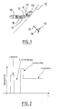
- the detection of missiles is within the general framework of the detection of a quasi-point object by an optronic system 11 mounted on planes 10.
- the optronic system 11 is an imager, composed of an optics 112 and a matrix detector 111.
- missile detection must be omnidirectional.
- the missiles to be detected are surface-to-air or air-to-air missiles. These are quasi-point objects with respect to the aircraft 10 or to the environment observed in the field 16, and highly mobile in the terrestrial reference system. Their speed is of the order of Mach 2.5.
- the time profile of the infrared emission of these missiles consists of several phases, which correspond to different phases of flight.
- the missile 15 Following its ejection 1, the missile 15 has a speed of the order of 50 m / s. Then the missile 15 undergoes a strong acceleration (from 30 to 50 g) for 1 to 2 seconds (phase 3), to lead it at a speed of the order of 500 to 700 m / s (phase 4). This speed is kept more or less constant for 5 to 15 seconds.
- the invention proposes to overcome at least one of these disadvantages.
- the invention also relates to a detection device implementing the method.
- the invention has many advantages.
- phase 1 ejection detects in particular phase 1 ejection, which is a brief event (of the order of 50 ms) and limited in space. It is therefore a high frequency event from a space-time point of view.
- phase 1 ejection or "early warning” in the English terminology generally used by those skilled in the art) saves valuable time, and trigger faster countermeasures devices. 'plane. The safety of the aircraft is greatly increased.
- the detection of the object is carried out on all types of funds, namely uniform funds of the "clear sky” type, structured or cloudy sky bases, or urban, rural or natural soil bottoms.
- the detection technique according to the invention has a low false alarm rate.
- the present description advantageously applies to an example according to FIG. 1, namely the detection of a missile 15 for the self-protection of a transport or hunting aircraft 10.
- the missile 15 is of course located in an optical field 16 of an optronic system 11 mounted on the aircraft 10.
- the present invention applies very advantageously to a very short-range ground-to-air missile fired from a transmission device 14 carried by an infantryman 13.
- the invention also applies to any technique for detecting an object located in an optical field of an optronic system, mounted on a vehicle or a building.
- a detection device mainly comprises the optronic system 11.
- the optronic system 11 is an imager composed of an optics 112 and a matrix detector 111.
- the field 16 of optics 112 is the largest possible, preferably greater than 2 ⁇ steradian (sr).
- the matrix detector 111 comprises a matrix conventionally presenting a set of detection pixels.
- the detection device further comprises processing means 12 able to determine a spatio-temporal spectrum from a signal from the optoelectronic system 11. Such a determination step is described in more detail later in this description.
- a spatio-temporal filter 17 capable of filtering the spatio-temporal spectrum.
- the optronic system 11 acquires a sequence of images.
- the images are taken in the optical field 16 of the optoelectronic system 11.
- the processing means 12 determine a spatio-temporal spectrum from a signal from the optronic system 11 and representing the sequence of images.
- the spatio-temporal spectrum is determined for one-dimensional images, namely a signal from a pixel of the optoelectronic system 11. It will be understood that the determination of the spatio-temporal spectrum is done in practice. for each signal from a pixel of the optronic system 11.
- the following calculation establishes the spatio-temporal spectrum of a sequence of images S, obtained by translating the same image 1 D of position r over time t, at the speed v.
- S r ⁇ ⁇ t I ⁇ r ⁇ - v ⁇ ⁇ t
- I is an image defined by the electrical level coming from the detector (in the plane of realities )
- r is the position vector in the detector assumed to be fixed
- v is the frame rate vector of the image in the detector frame, resulting from the movement of the detector carrier.
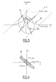
- FIGS. 3 and 4 (FIG. 4 being a projection of FIG. 3 in the plane k ⁇ ⁇ ⁇ ) show that the spectrum 31 obtained for the sequence S is therefore non-zero in magnitude (the magnitude is the third axis of the reference and is perpendicular to the plane k ⁇ ⁇ ⁇ ) only along a line 33 of slope -v in the plane k ⁇ ⁇ ⁇ .
- the envelope in magnitude is defined by the spectrum 32 of the one-dimensional image taken from the value ( ⁇ / v) (namely the image of the spectrum by an affinity).
- the spectrum 32 is zero on the points of the line situated beyond the point ( optical ⁇ max, optical K max ) where optical K max is the cutoff frequency of the optical system optronics and optical ⁇ max is equal to v multiplied by optical K max .
- the ejection 1 of the missile 15 is a short-lived signal which is, although not quite right, supposed to be driven by the movement of the back of the scene.
- I 0 is a function in the plane of reals describing the optical spot, ie the function obtained from the image detector when the system observes a point at infinity
- f (t) is the time profile of the emission (function of the time t), ie a positive function which is 0 before the firing of the missile and 1 when it is most visible.
- x and y designate the coordinates in the supposedly fixed detector.
- FIG. 6 is a projection of FIG. k ⁇ ⁇ ⁇
- the signal from the ejection of the missile 15 has a spectrum 41 which is extended in the frequency space ⁇ .
- FIG. 7 represents a mapping of the spectrum of FIG. 4 and the spectrum of FIG. 6.
- the mapping of Figure 7 shows that the filter 17 creates, in a third main step, search areas 71 in the spatio-temporal spectrum determined, to eliminate low spatial frequencies and low temporal frequencies.
- the filter can thus eliminate in particular the zone corresponding to a spectrum 31 of the signal from the bottom of the landscape scrolling. It is not possible to detect an ejection in the zone of the spectrum corresponding to line 33 or spectrum 31, because there would be a number of false alarms too important.
- the search areas 71 correspond to the frequencies which have the highest absolute values.
- Areas 72 corresponding to the areas of the spectrum 41 from which the 31-frequency spectrum of intermediate absolute value has been subtracted are not selected for detection.
- the speeds can take a large number of values. This phenomenon is particularly true in the case of large field images 16.
- the zones 81 correspond to mixed zones where the landscape and the ejection are superimposed.
- the estimation of the maximum speed can be variable depending on the position in the image, and be more or less precise if, for example, it is possible to know the movement of the wearer, and to take account of this knowledge for estimate the movements in the image.
- Figure 9 shows a spectrum, always in the case 1 D spatial, resulting from a sampling verifying, in space and time, the conditions of Shannon.
- the reference 93 shows the temporal sampling pulse and the reference 94 shows the spatial sampling pulse. It can be seen that, as previously, search zones 71 can be determined.
- Figure 10 shows a spectrum, always in the case 1 D spatial, resulting from a sampling satisfying the conditions of Shannon in space, but not verifying them in time. It is therefore classically a folding frequency spectrum.
- the search areas 71 are reduced and shifted to the low frequencies. The consequence of spectral folding is therefore to reduce the surface of the search areas.
- Frequency resolution is directly related to the size of the spatio-temporal portion considered for detection. As shown in FIG. 11, as the traveling speed v increases, the area of the spectrum 41 corresponding to the signal to be detected decreases.
- the detection means 18 detect in the search zones 71 alarm zones whose spectrum magnitude is greater than a predetermined threshold. These alarm zones correspond to a possible ejection of the object.
- the detection device can then give an instruction for triggering the countermeasure devices.
- Figure 12 schematically represents the main steps of such a method according to the invention.
- the optronic system 11 acquires a sequence of images.
- the images are taken in the optical field 16 of the optoelectronic system 11.
- the spatio-temporal spectrum 120 is determined during the step 120.
- Step 121 the filter 17 performs a point spatial detection filtering.
- Step 122 is advantageously used to eliminate objects that are obviously too bulky to be missiles 15.
- Step 122 which is also optional, the filter 17 performs anti-twist filtering.
- Step 122 is advantageously implemented under downsampling conditions.
- a counter N is then set to zero.
- the filter 17 creates search zones 71 in the spatio-temporal spectrum 41 by first filtering by a nonlinear morphological filter.
- This filter corresponds to a one-time temporal detection filtering. This filtering decreases the level of the signal coming from the background of the scene, but not that coming from the ejection.
- the filter 17 then performs a filtering of the signal from the nonlinear morphological filter by a low-pass spatial filter.
- This filter corresponds to a pixel magnification. Growing the size of the pixel makes it possible to reduce the proportion of high frequency signal in the signal leaving the pixel. This filter is advantageously used in cases where the conditions of low scrolling of the scene are not met.
- step 124 the counter N is incremented by one increment.
- the filter determines whether the value of the counter is less than a maximum value Nmax.
- the filter 17 returns to the step 123 already described. If the answer is no, the filter then proceeds to a step 126.
- step 123 and step 124 may be iterated a plurality of times.
- the number of iterations and the number Nmax are related to the frequency selectivity of the filter. The higher the speed of scrolling, the more the filter must be selective, especially in frequency, and the number of iterations must be important. In return, the greater the number of iterations, the larger the size of the filter response is also important.
- the filter is all the less localized as there are iterations.
- the filter 17 finally performs a filtering of the signal from the low-pass spatial filter by a non-linear morphological filter. Indeed, during the step 124, it is possible that a low frequency part time has appeared. It is then useful to reapply the temporal processing to select only the likely components of the signal. Indeed, the low temporal frequencies can not come from an ejection, whose duration is brief, whatever the spatial scale to which it is considered.
- the detection means 18 detect alarm signals whose magnitude is greater than a predetermined threshold. These alarm zones correspond to a possible ejection of the object. We set the value of the threshold according to the rate of false alarms that we want to obtain.
- FIG. 13A schematically represents a part of a spatio-temporal domain detected with an ejection 140 of a missile and a fixed point 141 without applying a method according to the invention.
- FIG. 13B schematically represents a part of a spatio-temporal domain detected with an ejection 140 of a missile and two mobile points 142 and 143 without applying a method according to the invention.
- the detection device does not detect the ejection 140 of the object, because of the detection also of the other points 141, 142 and 143. There is undifferentiation between the phenomena.
- FIG. 14 schematically represents the domain of FIG. 13B by applying a method according to the invention.
- the spatial point filter of step 121 is the Laplacian of the optical spot corresponding to a pixel, this spot being a Gaussian.
- the structuring element of the nonlinear morphological filter of step 123 is of a duration of five samples.
- the low-pass filter of step 124 is a constant function equal to 1 in seven pixels.
- the Nmax parameter is set to 2, so there are three nonlinear temporal morphological filters.
Landscapes
- Engineering & Computer Science (AREA)
- General Engineering & Computer Science (AREA)
- Physics & Mathematics (AREA)
- Chemical & Material Sciences (AREA)
- Combustion & Propulsion (AREA)
- Electromagnetism (AREA)
- General Physics & Mathematics (AREA)
- Radar, Positioning & Navigation (AREA)
- Remote Sensing (AREA)
- Image Analysis (AREA)
- Optical Radar Systems And Details Thereof (AREA)
Applications Claiming Priority (1)
| Application Number | Priority Date | Filing Date | Title |
|---|---|---|---|
| FR0509000A FR2890451B1 (fr) | 2005-09-02 | 2005-09-02 | Procede de detection d'un objet par traitement spatio-temporel et dispositif de mise en oeuvre du procede |
Publications (1)
| Publication Number | Publication Date |
|---|---|
| EP1772743A1 true EP1772743A1 (de) | 2007-04-11 |
Family
ID=36480940
Family Applications (1)
| Application Number | Title | Priority Date | Filing Date |
|---|---|---|---|
| EP06120017A Withdrawn EP1772743A1 (de) | 2005-09-02 | 2006-09-01 | Verfahren zur Erfassung eines Objekts mittels Raum-Zeit-Verarbeitung und Vorrichtung zur Umsetzung dieses Verfahrens |
Country Status (2)
| Country | Link |
|---|---|
| EP (1) | EP1772743A1 (de) |
| FR (1) | FR2890451B1 (de) |
Citations (7)
| Publication number | Priority date | Publication date | Assignee | Title |
|---|---|---|---|---|
| FR2465188A1 (fr) * | 1980-11-03 | 1981-03-20 | Trt Telecom Radio Electr | Dispositif pour detecter un point chaud dans un paysage percu selon un rayonnement infrarouge et systeme de guidage d'un missile sur une cible, comportant un tel dispositif |
| DE3014906C1 (de) * | 1980-04-18 | 1981-10-08 | Eltro GmbH, Gesellschaft für Strahlungstechnik, 6900 Heidelberg | Spektralselektrionseinrichtung |
| FR2536534A1 (fr) * | 1978-07-03 | 1984-05-25 | France Etat Armement | Procede et dispositif de detection selective de vehicules |
| EP0241374A1 (de) * | 1986-04-11 | 1987-10-14 | Thomson-Csf | Optronische Abweichungsvorrichtung zur räumlichen und spektralen Erkennung von infraroten Lichtquellen |
| US4937878A (en) * | 1988-08-08 | 1990-06-26 | Hughes Aircraft Company | Signal processing for autonomous acquisition of objects in cluttered background |
| FR2660998A1 (fr) * | 1980-06-06 | 1991-10-18 | Thomson Trt Defense | Dispositif pour detecter un point chaud dans un paysage percu selon un rayonnement infrarouge et systeme de guidage d'un missile sur une cible comportant un tel dispositif. |
| FR2736742A1 (fr) * | 1995-07-13 | 1997-01-17 | Thomson Csf | Procede de mesure de deplacements dans une sequence d'images |
-
2005
- 2005-09-02 FR FR0509000A patent/FR2890451B1/fr not_active Expired - Lifetime
-
2006
- 2006-09-01 EP EP06120017A patent/EP1772743A1/de not_active Withdrawn
Patent Citations (7)
| Publication number | Priority date | Publication date | Assignee | Title |
|---|---|---|---|---|
| FR2536534A1 (fr) * | 1978-07-03 | 1984-05-25 | France Etat Armement | Procede et dispositif de detection selective de vehicules |
| DE3014906C1 (de) * | 1980-04-18 | 1981-10-08 | Eltro GmbH, Gesellschaft für Strahlungstechnik, 6900 Heidelberg | Spektralselektrionseinrichtung |
| FR2660998A1 (fr) * | 1980-06-06 | 1991-10-18 | Thomson Trt Defense | Dispositif pour detecter un point chaud dans un paysage percu selon un rayonnement infrarouge et systeme de guidage d'un missile sur une cible comportant un tel dispositif. |
| FR2465188A1 (fr) * | 1980-11-03 | 1981-03-20 | Trt Telecom Radio Electr | Dispositif pour detecter un point chaud dans un paysage percu selon un rayonnement infrarouge et systeme de guidage d'un missile sur une cible, comportant un tel dispositif |
| EP0241374A1 (de) * | 1986-04-11 | 1987-10-14 | Thomson-Csf | Optronische Abweichungsvorrichtung zur räumlichen und spektralen Erkennung von infraroten Lichtquellen |
| US4937878A (en) * | 1988-08-08 | 1990-06-26 | Hughes Aircraft Company | Signal processing for autonomous acquisition of objects in cluttered background |
| FR2736742A1 (fr) * | 1995-07-13 | 1997-01-17 | Thomson Csf | Procede de mesure de deplacements dans une sequence d'images |
Also Published As
| Publication number | Publication date |
|---|---|
| FR2890451B1 (fr) | 2009-05-29 |
| FR2890451A1 (fr) | 2007-03-09 |
Similar Documents
| Publication | Publication Date | Title |
|---|---|---|
| EP2795580B1 (de) | Verfahren zur schätzung des optischen flusses auf basis eines asynchronen lichtsensors | |
| EP3200153B1 (de) | Verfahren zur erkennung von bodenzielen in bewegung aus einem videodatenstrom, welcher mit einer kamera an bord eines flugzeugs aufgenommen wurde | |
| EP3103062B1 (de) | Verfahren zur bestimmung und klassifizierung von ereignissen in einer szene | |
| EP3241035B1 (de) | Radargestütztes optisches spurfolgeverfahren und einsatzsystem zur durchführung dieses verfahrens | |
| EP1298592B1 (de) | Stabilisierung von Bildern einer Szene, Korrigierung der Grauwertverschiebung, Erfassung bewegender Objekte und auf Bildstabilisierung basierter Abgleich von zwei Bildaufnahmevorrichtungen | |
| EP3268691B1 (de) | Luftgestützte vorrichtung zur detektion von schüssen und zur nachweis und zur steuerungsassistenz | |
| EP2333481A1 (de) | Optronisches System und Verfahren zur Herstellung dreidimensionaler Bilder zur Identifikation | |
| FR2736149A1 (fr) | Dispositif de reconnaissance et de poursuite d'objets | |
| EP4526212B1 (de) | Verfahren und vorrichtung zur bestimmung einer richtregel für einen satelliten durch bestimmung einer raum-zeit-verteilung | |
| EP2239597A1 (de) | Multi-Mode-Bodenüberwachungsradar für Flughäfen | |
| EP3915040B1 (de) | Verfahren zur bestimmung eines konfidenzscores für ein ziel in der umgebung eines fahrzeugs | |
| EP2544020B1 (de) | Verfahren und Vorrichtung zur Detektion eines Ziels, das von starken Energiereflektoren maskiert wird | |
| FR2962827A1 (fr) | Procede et dispositif d'imagerie bi-spectral multifonctions. | |
| EP2294441B1 (de) | Verfahren zur erkennung eines objekts in einer szene mit artefakten | |
| WO2022018381A1 (fr) | Procede et systeme pour detecter une ou plusieurs cibles dans l'espace a partir d'images prises depuis un engin spatial tel qu'un satellite d'inspection visuelle, et satellite equipe d'un tel systeme | |
| WO2020260649A1 (fr) | Dispositif radar pour la détection d'un comportement de référence de cibles pistées; procédé et produit programme d'ordinateur associés | |
| EP4115327B1 (de) | Verfahren zur unterstützung der detektion von elementen und zugehörige vorrichtung und plattform | |
| WO2006008227A1 (fr) | Procede de tfac par segmentation statistique et normalisation | |
| EP1772743A1 (de) | Verfahren zur Erfassung eines Objekts mittels Raum-Zeit-Verarbeitung und Vorrichtung zur Umsetzung dieses Verfahrens | |
| EP2796893B1 (de) | Verfahren zum Ausblenden von Störechos bei der SAR-Bildgebung | |
| EP1570433B1 (de) | Bildverarbeitungseinrichtung mit erkennung und auswahl von lichtquellen | |
| EP1845403B1 (de) | System und Verfahren zur Stabilisierung einer Visierlinie | |
| EP3072110B1 (de) | Verfahren zur schätzung der bewegung eines objekts | |
| EP3757942B1 (de) | Verfahren und vorrichtung zur passiven telemetrie durch bildverarbeitung | |
| EP1718067A1 (de) | Im Flugzeug eingebautes Überwachungsverfahren und -system mittels Infrarotbilderanalyse |
Legal Events
| Date | Code | Title | Description |
|---|---|---|---|
| PUAI | Public reference made under article 153(3) epc to a published international application that has entered the european phase |
Free format text: ORIGINAL CODE: 0009012 |
|
| AK | Designated contracting states |
Kind code of ref document: A1 Designated state(s): AT BE BG CH CY CZ DE DK EE ES FI FR GB GR HU IE IS IT LI LT LU LV MC NL PL PT RO SE SI SK TR |
|
| AX | Request for extension of the european patent |
Extension state: AL BA HR MK YU |
|
| RIN1 | Information on inventor provided before grant (corrected) |
Inventor name: RICHARD, YVES |
|
| 17P | Request for examination filed |
Effective date: 20071005 |
|
| 17Q | First examination report despatched |
Effective date: 20071107 |
|
| AKX | Designation fees paid |
Designated state(s): AT BE BG CH CY CZ DE DK EE ES FI FR GB GR HU IE IS IT LI LT LU LV MC NL PL PT RO SE SI SK TR |
|
| STAA | Information on the status of an ep patent application or granted ep patent |
Free format text: STATUS: THE APPLICATION IS DEEMED TO BE WITHDRAWN |
|
| 18D | Application deemed to be withdrawn |
Effective date: 20140401 |