EP1772923A2 - Brennstoffzellen-Stapel mit Zellspannungsmessklemmen - Google Patents
Brennstoffzellen-Stapel mit Zellspannungsmessklemmen Download PDFInfo
- Publication number
- EP1772923A2 EP1772923A2 EP06121886A EP06121886A EP1772923A2 EP 1772923 A2 EP1772923 A2 EP 1772923A2 EP 06121886 A EP06121886 A EP 06121886A EP 06121886 A EP06121886 A EP 06121886A EP 1772923 A2 EP1772923 A2 EP 1772923A2
- Authority
- EP
- European Patent Office
- Prior art keywords
- cell voltage
- fuel
- wiring lines
- cell
- voltage measurer
- Prior art date
- Legal status (The legal status is an assumption and is not a legal conclusion. Google has not performed a legal analysis and makes no representation as to the accuracy of the status listed.)
- Granted
Links
Images


Classifications
-
- H—ELECTRICITY
- H01—ELECTRIC ELEMENTS
- H01M—PROCESSES OR MEANS, e.g. BATTERIES, FOR THE DIRECT CONVERSION OF CHEMICAL ENERGY INTO ELECTRICAL ENERGY
- H01M8/00—Fuel cells; Manufacture thereof
- H01M8/24—Grouping of fuel cells, e.g. stacking of fuel cells
- H01M8/2465—Details of groupings of fuel cells
- H01M8/247—Arrangements for tightening a stack, for accommodation of a stack in a tank or for assembling different tanks
- H01M8/248—Means for compression of the fuel cell stacks
-
- H—ELECTRICITY
- H01—ELECTRIC ELEMENTS
- H01M—PROCESSES OR MEANS, e.g. BATTERIES, FOR THE DIRECT CONVERSION OF CHEMICAL ENERGY INTO ELECTRICAL ENERGY
- H01M8/00—Fuel cells; Manufacture thereof
- H01M8/04—Auxiliary arrangements, e.g. for control of pressure or for circulation of fluids
-
- H—ELECTRICITY
- H01—ELECTRIC ELEMENTS
- H01M—PROCESSES OR MEANS, e.g. BATTERIES, FOR THE DIRECT CONVERSION OF CHEMICAL ENERGY INTO ELECTRICAL ENERGY
- H01M8/00—Fuel cells; Manufacture thereof
- H01M8/04—Auxiliary arrangements, e.g. for control of pressure or for circulation of fluids
- H01M8/04298—Processes for controlling fuel cells or fuel cell systems
- H01M8/04313—Processes for controlling fuel cells or fuel cell systems characterised by the detection or assessment of variables; characterised by the detection or assessment of failure or abnormal function
- H01M8/04537—Electric variables
- H01M8/04544—Voltage
- H01M8/04552—Voltage of the individual fuel cell
-
- H—ELECTRICITY
- H01—ELECTRIC ELEMENTS
- H01M—PROCESSES OR MEANS, e.g. BATTERIES, FOR THE DIRECT CONVERSION OF CHEMICAL ENERGY INTO ELECTRICAL ENERGY
- H01M8/00—Fuel cells; Manufacture thereof
- H01M8/04—Auxiliary arrangements, e.g. for control of pressure or for circulation of fluids
- H01M8/04298—Processes for controlling fuel cells or fuel cell systems
- H01M8/04313—Processes for controlling fuel cells or fuel cell systems characterised by the detection or assessment of variables; characterised by the detection or assessment of failure or abnormal function
- H01M8/04537—Electric variables
- H01M8/04544—Voltage
- H01M8/04559—Voltage of fuel cell stacks
-
- H—ELECTRICITY
- H01—ELECTRIC ELEMENTS
- H01M—PROCESSES OR MEANS, e.g. BATTERIES, FOR THE DIRECT CONVERSION OF CHEMICAL ENERGY INTO ELECTRICAL ENERGY
- H01M8/00—Fuel cells; Manufacture thereof
- H01M8/24—Grouping of fuel cells, e.g. stacking of fuel cells
- H01M8/241—Grouping of fuel cells, e.g. stacking of fuel cells with solid or matrix-supported electrolytes
-
- H—ELECTRICITY
- H01—ELECTRIC ELEMENTS
- H01M—PROCESSES OR MEANS, e.g. BATTERIES, FOR THE DIRECT CONVERSION OF CHEMICAL ENERGY INTO ELECTRICAL ENERGY
- H01M8/00—Fuel cells; Manufacture thereof
- H01M8/24—Grouping of fuel cells, e.g. stacking of fuel cells
- H01M8/2465—Details of groupings of fuel cells
-
- H—ELECTRICITY
- H01—ELECTRIC ELEMENTS
- H01M—PROCESSES OR MEANS, e.g. BATTERIES, FOR THE DIRECT CONVERSION OF CHEMICAL ENERGY INTO ELECTRICAL ENERGY
- H01M8/00—Fuel cells; Manufacture thereof
- H01M8/10—Fuel cells with solid electrolytes
- H01M2008/1095—Fuel cells with polymeric electrolytes
-
- H—ELECTRICITY
- H01—ELECTRIC ELEMENTS
- H01M—PROCESSES OR MEANS, e.g. BATTERIES, FOR THE DIRECT CONVERSION OF CHEMICAL ENERGY INTO ELECTRICAL ENERGY
- H01M8/00—Fuel cells; Manufacture thereof
- H01M8/10—Fuel cells with solid electrolytes
- H01M8/1009—Fuel cells with solid electrolytes with one of the reactants being liquid, solid or liquid-charged
- H01M8/1011—Direct alcohol fuel cells [DAFC], e.g. direct methanol fuel cells [DMFC]
-
- Y—GENERAL TAGGING OF NEW TECHNOLOGICAL DEVELOPMENTS; GENERAL TAGGING OF CROSS-SECTIONAL TECHNOLOGIES SPANNING OVER SEVERAL SECTIONS OF THE IPC; TECHNICAL SUBJECTS COVERED BY FORMER USPC CROSS-REFERENCE ART COLLECTIONS [XRACs] AND DIGESTS
- Y02—TECHNOLOGIES OR APPLICATIONS FOR MITIGATION OR ADAPTATION AGAINST CLIMATE CHANGE
- Y02E—REDUCTION OF GREENHOUSE GAS [GHG] EMISSIONS, RELATED TO ENERGY GENERATION, TRANSMISSION OR DISTRIBUTION
- Y02E60/00—Enabling technologies; Technologies with a potential or indirect contribution to GHG emissions mitigation
- Y02E60/30—Hydrogen technology
- Y02E60/50—Fuel cells
Definitions
- the present invention relates to a fuel cell system, and more particularly, to a cell voltage measurer of a fuel cell stack and a fuel cell system using the same, in which a wiring line is protected and its structure is simplified.
- a fuel cell directly transforms chemical energy of fuel into electric energy by an electrochemical reaction.
- a fuel cell can generate electric energy by using a reaction of hydrogen and oxygen to produce water.
- Representative examples of a fuel cell include phosphate fuel cells, molten carbonate fuel cells, solid oxide fuel cells, polymer electrolyte membrane fuel cells, and alkaline fuel cells, according to the kinds of electrolytes used.
- a polymer electrolyte membrane fuel cell has a relatively high output performance and a relatively quick start and response time. Also, the PEMFC can operate at a relatively low temperature. As such, the PEMFC can be used as a transportable power source for a portable electronic apparatus or a vehicle, as well as a distributed power source such as a stationary power plant for a house or a public structure.
- a direct methanol fuel cell is similar to the PEMFC because it uses a solid polymer as an electrolyte.
- the DMFC differs from the PEMFC in that its stack can be directly supplied with a liquid fuel such as methanol (without a reformer therebetween). Since the DMFC does not need to use a reformer, it can be smaller in size than the PEMFC.
- a fuel cell e.g., a PEMFC or a DMFC
- the stack includes a membrane electrode assembly (MEA), and a separator or a bipolar plate to supply fuel and an oxidant to an anode electrode and a cathode electrode of the MEA, respectively.
- MEA membrane electrode assembly
- separator or the bipolar plate to supply fuel and an oxidant to an anode electrode and a cathode electrode of the MEA, respectively.
- the MEA and the separator (or the bipolar plate) form a cell unit (or unit cell) and are alternately stacked to form the stack.
- a fuel cell stack including a plurality of stacked cell units (or unit cells) can deteriorate after a long usage time.
- the plurality of stacked cell units do not deteriorate uniformly due to differences in their structure or position.
- the pressure of the fuel supplied to the cell unit adjacent to an anode inlet is higher than that supplied to the cell unit adjacent to an anode outlet, so that the cell unit adjacent to the anode inlet is stressed and deteriorated more than the cell unit adjacent to the anode outlet.
- the lifespan of the conventional fuel cell stack is shortened due to the differences of the rates of deterioration of the cell units.
- the conventional fuel cell stack can be used continuously as long as the stack outputs a voltage higher than a referenced (or predetermined) level even though a certain cell unit is more deteriorated than other cell units.
- the fuel cell stack may suddenly stop operating when the certain cell unit stops working due to the deterioration.
- a cell voltage measurer for a fuel cell stack including: membrane-electrode assemblies and separators alternatively stacked with the membrane-electrode assemblies to form a stacked structure; a pair of end plates for supporting opposite sides of the stacked structure; and fastening mechanisms for fastening the pair of end plates, the cell voltage measurer including: a plurality of terminals electrically connected to the separators, respectively; and a plurality of wiring lines coupled to at least one of the fastening mechanisms and electrically connected to the plurality of terminals, respectively.
- a fuel cell system in another embodiment, includes: a fuel cell stack including: a plurality of membrane-electrode assemblies, each of the membrane-electrode assemblies including an anode electrode, a cathode electrode, and an electrolyte membrane between the anode electrode and the cathode electrode; a plurality of separators alternatively stacked with the membrane-electrode assemblies to form a stacked structure; a pair of end plates supporting opposite sides of the stacked structure; and fastening mechanisms for fastening the pair of end plate; and a cell voltage measurer including a plurality of terminals electrically connected to the plurality of separators, respectively; and a plurality of wiring lines coupled to at least one of the fastening mechanisms and electrically connected to the plurality of terminals, respectively.
- the cell voltage measurer further includes: a voltage sensor electrically connected with the plurality of wiring lines and being adapted to sense one or more voltages applied at the plurality of wiring lines.
- the voltage sensor includes: at least two switching units, each of the at least two switching units having a plurality of input terminals and an output terminal, and being adapted to selectively, electrically connect one of the input terminals with the output terminal; and a switching controller for sensing a voltage applied at the terminals of the at least two switching units and for controlling the at least two switching units.
- a fuel cell stack 100 includes an MEA 110, a separator 120 coupled to opposite sides of the MEA 110, end plates 130a and 130b, and fastening mechanisms (e.g., fastening bars) 140a, 140b, 140c and 140d, which form one or more cell units (or unit cells).
- a cell voltage measurer according to an embodiment of the present invention is connected to the fuel cell stack 100 through at least one of the fastening mechanisms 140a, 140b, 140c and 140d of the fuel cell stack 100 to stably measure a cell voltage of each cell unit (or unit cell) provided in the fuel cell stack 100.
- the cell voltage measurer includes a plurality of terminals 150 inserted in and fastened with each separator 120 of the fuel cell stack 100; and a plurality of wiring lines 160 electrically connected to each terminal 150.
- the plurality of wiring lines 160 are coupled to the fastening mechanisms (or fastening bar) 140a.
- the fastening bar 140a is formed with a hollow (or cavity) 146 through which the plurality of wiring lines 160 pass, and one or more holes 147 respectively through which one or more of the wiring lines 160 pass.
- the cell voltage measurer includes a voltage sensor 170 connected to the plurality of wiring lines 160 to measure one or more voltages respectively at one or more of the wiring lines 160.
- the MEA 110 has a structure such that an anode electrode (referred to as a “fuel electrode” or an “oxidation electrode”) and a cathode electrode (referred to as an "air electrode” or a “reduction electrode”) are attached to opposite sides of a polymer electrolyte membrane.
- the anode electrode is provided with a catalyst layer for oxidation of the fuel
- the cathode electrode is provided with a catalyst layer for reduction of an oxidant.
- the separators 120 can be implemented by any suitable bipolar plates that include a first channel to supply the anode electrode with the fuel, and a second channel to supply the cathode electrode with the oxidant.
- the MEA 110 and the separator 120 are alternatively stacked. Additionally, a gasket may be interposed between the MEA 110 and the separator 120 in order to block or prevent the fuel and the oxidant from leakage.
- the end plates 130a and 130b are placed at the opposite sides of the stacked structure formed by the MEA 110 and the separator 120, and apply a certain (or predetermined) pressure from the opposite sides toward the center of the stacked structure.
- the fastening mechanisms 140a, 140b, 140c and 140d connect the two end plates 130a and 130b, and apply a certain (or predetermined) fastening force to the two end plates 130a and 130b.
- the fastening mechanisms 140a, 140b, 140c and 140d include threaded bodies or shafts 141a, 141b, 141c and 141d; opposite ends 142a, 143a, 142b, 143b, 142c, 143c, 142d and 143d; and nuts 144a, 145a, 144b, 145b, 144c, 145c, 144d and 145d.
- the fastening mechanisms 140a to which one or more of the wiring lines 160 are connected include the hollow 146 that runs the length of the fastening bar 140a, into which the plurality of wiring lines 160 are inserted, and the holes 147 through which the wiring lines 160 to be connected with one or more of the terminals 150 pass.
- the holes 147 are located corresponding to the separators 120 respectively connected with the terminals 150.
- the holes 147 may comprise an opening placed corresponding to the respective separators 120 and through which the hollow 146 is exposed; however, the invention is not thereby limited.
- the fastening mechanism 140a is made of a material selected from a group consisting of metal, a complex material, and combination thereof.
- the terminal 150 is electrically connected to the separator 120.
- the terminal 150 can be implemented by (or includes) an electrode pin.
- the electrode pin is adapted to insert into a groove placed in a lateral side of a corresponding one of the separators 120.
- the terminal 150 may be stuck like a needle into a carbon cloth forming the anode electrode and/or the cathode electrode to thereby allow for a stable connection between the terminal 150 and the carbon cloth.
- the terminal 150 may be implemented by a surface electrode using a suitable clip or adhesive.
- Each wiring line 160 allows the voltage at a respective terminal 150 to be applied to the voltage sensor 170.
- the wiring line 160 has a first end connected to the terminal 150 and a second end connected to the voltage sensor 170, and is extended through the hole 147 and the hollow 146 of the fastening bar 140a.
- the wiring lines 160 can be implemented by a cable 160a that includes a plurality of wires surrounded with a coating layer for insulating and protecting the wires.
- the voltage sensor 170 is connected to the plurality of terminals 150 connected to each cell unit (or unit cell) of the fuel cell stack 100 by the plurality of wiring lines 160, and measures a voltage level of each cell unit (or unit cell).
- An example of the voltage sensor 170 will be described in more detail with reference to Figure 3.
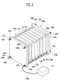
- Figure 2 is a perspective view of a cell voltage measurer for a fuel cell stack 100a according to another embodiment of the present invention.
- the fuel cell stack 100a includes an MEA 110, a separator 120 stacked on and electrically coupled to opposite sides of the MEA 110, end plates 130a and 130b, and fastening mechanisms 140e, 140b, 140c and 140d, which form one or more cell units (or unit cells).
- a cell voltage measurer according to this embodiment of the present invention is connected to the fuel cell stack 100 through at least one of the fastening mechanisms 140e, 140b, 140c and 140d of the fuel cell stack 100 to stably measure a cell voltage of each cell unit (or unit cell) provided in the fuel cell stack 100.
- the cell voltage measurer includes a plurality of terminals 150 inserted in and fastened with each separator 120 of the fuel cell stack 100a; a plurality of wiring lines 160 electrically connected to each terminal 150; and a voltage sensor 170 electrically connected with the plurality of wiring lines 160 and adapted to measure one or more voltages respectively applied at the one or more wiring lines 160.
- the plurality of wiring lines 160 are coupled to the fastening mechanism 140e.
- the fastening mechanism 140e is formed with a lateral opening 146e through which the plurality of wiring lines 160 pass, and a plurality of slits 147e provided corresponding to the separators 120 and through which the wiring lines 160 respectively pass.
- the fastening mechanisms 140e may have a bar-shaped body (or a threaded body or formed as a fastening bar) 141e, and the lateral opening 146e may be formed from one end 142e to another end 143e of the bar-shaped body 141e of the fastening mechanisms 140e; however, the invention is not thereby limited.
- the fastening mechanisms 140e may have a structure such that the lateral opening 146e is not formed in the end 143e.
- the slit 147e may be provided corresponding to each separator 120 and having a width and a length to properly and easily align and settle the wiring lines 160 from the lateral opening 146e; however, the invention is not thereby limited.
- the fastening mechanisms has a structure such that the plurality of wiring lines 160 can be inserted in its inside or its opening, and a structure that defined a position of where each wiring line 160 is withdrawn, so that the wiring line 160 is blocked or prevented from being deteriorated or damaged due to direct contact with the stack. Further, in this embodiment, the end of the wiring line 160 and the terminal 150 for measuring the voltage of each cell unit (or unit cell) are stably and easily coupled to each other.
- a separate member for protecting the wiring line and/or a separate member for holding/guiding the wiring line are not needed, so that the structure of the embodiment of the present invention is simplified as compared with an example needing the separate member for protecting the wiring line and/or the separate member for holding/guiding the wiring line.
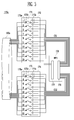
- Figure 3 is a block diagram of a voltage sensor provided in a cell voltage measurer for a fuel cell stack according to an embodiment of the present invention.
- the voltage sensor 170a of the cell voltage measurer includes first and second switching units 172 and 174 to measure each voltage of the plurality of cell units (or unit cells), and a switching controller 176 to control the first and second switching units 172 and 174.
- the first switching unit 172 includes a plurality of switching mechanisms 173 turned on/off in response to a control signal CS1.
- the plurality of switching mechanisms 173 include input terminals 173a connected in sequence to the terminals connected to the odd-numbered cell units (or unit cells) among the cell units (or unit cells) of the fuel cell stack, respectively; output terminals 173b connected to the switching controller 176 (as a single or one output terminal); and control terminals 173c.
- the plurality of switching mechanisms 173 are selectively turned on and off in response to the control signal CS1 of the switching controller 176.
- the second switching unit 174 includes a plurality of switching mechanisms 175 turned on/off in response to a control signal CS2.
- the plurality of switching mechanisms 175 include input terminals 175a connected in sequence to the terminals connected to the even-numbered cell units among the cell units of the fuel cell stack, respectively; output terminals 175b connected to the switching controller 176 (as a single or one output terminal); and control terminals 175c.
- the plurality of switching means 175 are selectively turned on and off in response to the control signal CS2 of the switching controller 176.
- the switching mechanisms 173 and 175 can be implemented by a semiconductor device such as a field effect transistor (FET) or the like, and the first and the second switching units 172 and 174 can be implemented by a semiconductor chip.
- FET field effect transistor
- the switching controller 176 includes an input terminal 177 connected to the output terminals of the first and second switching units 172 and 174, and an output terminal 178 connected to the control terminal of the first and second switching units 172 and 174.
- the switching controller 176 senses the voltage applied at (or between) the output terminals of the first and second switching units 172 and 174.
- the switching controller 176 generates the control signals CS1 and CS2, and transmits the control signals CS1 and CS2 to the switching mechanisms 173 of the first switching unit 172 and the switching mechanisms 175 of the second switching unit 174, thereby sensing the voltage of all cell units (or unit cells) in sequence or sensing the voltage of a certain cell (or cell unit).
- the control signals CS1 and CS2 can be transmitted to the control terminals 173c and 175c with signal amplification.
- the input terminal 177 can be implemented by an analog-digital converter, and the switching controller 176 can be implemented by a digital signal processing unit (DPU) such as a microprocessor unit (MPU).
- DPU digital signal processing unit
- MPU microprocessor unit
- the DPU includes various fuel cell controllers that have an arithmetic logic unit (ALU) to perform calculation, a register to temporarily store data and command(s), and a controller to control operation of the fuel cell stack.
- ALU arithmetic logic unit
- the DPU includes at least one of processors having various architectures, such as Alpha of Digital; MIPS of MIPS Technologies, NEC, IDT, Siemens, etc.; x86 of Intel and Cyrix, AMD and Nexgen; and Power PC of IBM and Motorola.
- FIG 4 is a schematic block diagram of a fuel cell system using a cell voltage measurer according to an embodiment of the present invention.
- configurations of a fuel cell stack 100 including a cell voltage measurer is substantially equal to the stack 100 of Figure 1 and the stack 100a of Figure 2.
- a fuel cell system 200 includes the fuel cell stack 100; a cell voltage measurer having a cable 160a and a voltage sensor 170; a fuel feeder; and an oxidant feeder 190.
- the fuel cell stack 100 includes an MEA using a solid polymer membrane as an electrolyte membrane.
- the electrolyte membrane may include one or more hydrogen ion conductive polymers selected from a group consisting of perfluoride polymer, benzimidazole polymer, polyimide polymer, polyetherimide polymer, polyphenylenesulfide polymer, polysulfone polymer, polyethersulfone polymer, polyetherketone polymer, polyether-etherketone polymer, polyphenylquinoxaline polymer, and combinations thereof; however, the invention is not thereby limited.
- the electrolyte membrane includes one or more hydrogen ion conductive polymers selected from a group consisting of poly(perfluorosulfone acid), poly(perfluorocarboxyl acid), copolymer of fluorovinylether and tetrafluoroethylene including sulfonic acid, defluoride polyetherketone sulfide, aryl ketone, poly(2,2'-(m-phenylene)-5,5'-bibenzimidazole) poly(2,5-benzimidazole), and combinations thereof; however, the invention is not thereby limited.
- poly(perfluorosulfone acid) poly(perfluorocarboxyl acid)
- copolymer of fluorovinylether and tetrafluoroethylene including sulfonic acid, defluoride polyetherketone sulfide, aryl ketone, poly(2,2'-(m-phenylene)-5,5'-bibenzimidazole) poly(2,
- Each of the anode electrode and the cathode electrode placed on opposite sides of the electrolyte membrane may include a catalyst layer and a diffusing layer.
- the diffusing layer may include a microporous layer and a backing layer; however, the invention is not thereby limited
- the catalyst layer changes a reaction speed to quickly cause a chemical reaction between the fuel and the oxidant supplied to the respective electrodes.
- the microporous layer is implemented by coating the backing layer with a carbon layer.
- the microporous layer uniformly distributes fuel, water, air, etc.; collects produced electricity; and protects materials of the catalyst layer from being disintegrated (or washed away) by the fluid.
- the backing layer is implemented by a carbon material such as a carbon cloth, a carbon paper, etc., and supports the catalyst layer or the electrode. The backing layer diffuses a reaction material toward the catalyst layer, thereby allowing the reaction material to easily reach the catalyst layer.
- the catalyst layer may include one or more metal catalysts selected from a group consisting of one or more transition metals selected from a group consisting of platinum, ruthenium, osmium, platinum-ruthenium alloy, platinum-osmium alloy, platinum-palladium alloy, platinum-M alloy (where M includes Ga, Ti, V, Cr, Mn, Fe, Co, Ni, Cu and Zn), and combinations thereof; however, the invention is not thereby limited.
- metal catalysts selected from a group consisting of one or more transition metals selected from a group consisting of platinum, ruthenium, osmium, platinum-ruthenium alloy, platinum-osmium alloy, platinum-palladium alloy, platinum-M alloy (where M includes Ga, Ti, V, Cr, Mn, Fe, Co, Ni, Cu and Zn), and combinations thereof; however, the invention is not thereby limited.
- the catalyst layer may include one or more metal catalysts selected from a group consisting of platinum deposited on supports, ruthenium, osmium, platinum-ruthenium alloy, platinum-osmium alloy, platinum-palladium alloy, platinum-M alloy (where M includes one or more transition metals selected from a group consisting of Ga, Ti, V, Cr, Mn, Fe, Co, Ni, Cu and Zn), and combinations thereof.
- the supports can include any material as long as it is conductive.
- the supports may be carbon; however, the invention is not thereby limited
- the microporous layer may include one or more carbon materials selected from a group consisting of graphite, carbon nanotube (CNT), fullerene (C 60 ), activated carbon, vulcan, ketjen black, carbon black, and carbon nanohorn. Further, the microporous layer may include one or more binders selected from a group consisting of poly(perfluorosulfone acid), poly(tetrafluoroethylene), fluorinated ethylene-propylene, and combinations thereof.
- the fuel cell stack 100 includes separators alternately stacked with MEAs.
- the separator includes a certain (or predetermined) material that is non-porous (or substantially non-porous) to the fuel and the oxidant (e.g., air) to separate the fuel and the oxidant, has good electric conductivity, and a certain heat conductivity for controlling the temperature of the fuel cell. Further, the separator has mechanical strength strong enough to withstand a force of clamping the fuel cell stack 100, and is corrosion resistance to hydrogen ions.
- the fuel cell stack 100 is assembled by stacking the MEAs and the separators, placing the pair of end plates on the opposite sides of the stacked structure, and fastening the pair of end plates by fastening mechanisms with a certain (or predetermined) fastening force.
- the cell voltage measurer includes a plurality of terminals electrically connected to the plurality of separators, a plurality of wiring lines electrically connected to the plurality of terminals, and a fastening bar included in the fastening mechanisms and formed with a hollow through which the plurality of wiring lines pass and with one or more hole respectively through which one or more of the wiring lines pass. Further, the fuel cell measurer includes a voltage sensor electrically connected with the plurality of wiring lines withdrawn from the hollow of the fastening bar to sense the voltage applied at the plurality of wiring lines.
- the fuel feeder includes a fuel tank 180, a fuel pump 182, and a reformer 184.
- the fuel tank 180 stores hydrogen-containing fuel (or fuel containing hydrogen).
- the fuel pump 182 supplies the fuel from the fuel tank 180 to the fuel cell stack 100.
- the reformer 184 reforms the fuel and supplies a reformed gas including abundant hydrogen gas to the anode electrode of the fuel cell stack 100.
- the reformer 184 can be removed when the fuel cell stack 100 is capable of directly using liquid fuel.
- the oxidant feeder 190 supplies the oxidant, e.g., oxygen gas or air, to the cathode electrode of the fuel cell stack 100.
- the oxidant feeder 190 can be implemented by an air pump, a blower, etc.
- the wiring line for measuring each voltage of each of the cells (or cell units) of the fuel cell stack is protected, and its structure is simplified, so that each voltage of each of the cells is stably measured, thereby stably controlling the fuel cell stack to operate according to the measured state of each cell and decreasing the deterioration of the fuel cell stack.
- the lifespan of the fuel cell stack is extended.
- an embodiment of the present invention provides a cell voltage measurer of a fuel cell stack and a fuel cell system using the same, in which the wiring line is blocked or prevented from being short-circuited by heat generated in the fuel cell stack, and its structure is simplified, thereby stably measuring the voltage of each cell (or cell unit).
- the fuel cell stack is blocked or prevented from being suddenly stopped by the stopping of a certain unit cell (or cell unit) of the fuel cell stack or when the measured voltage of a certain unit cell (or cell unit) is lower than a reference voltage.
Landscapes
- Life Sciences & Earth Sciences (AREA)
- Engineering & Computer Science (AREA)
- Manufacturing & Machinery (AREA)
- Sustainable Development (AREA)
- Sustainable Energy (AREA)
- Chemical & Material Sciences (AREA)
- Chemical Kinetics & Catalysis (AREA)
- Electrochemistry (AREA)
- General Chemical & Material Sciences (AREA)
- Fuel Cell (AREA)
Applications Claiming Priority (1)
| Application Number | Priority Date | Filing Date | Title |
|---|---|---|---|
| KR1020050094598A KR100646954B1 (ko) | 2005-10-07 | 2005-10-07 | 연료전지 스택의 셀 전압 측정장치 및 이를 채용한연료전지 시스템 |
Publications (3)
| Publication Number | Publication Date |
|---|---|
| EP1772923A2 true EP1772923A2 (de) | 2007-04-11 |
| EP1772923A3 EP1772923A3 (de) | 2010-05-26 |
| EP1772923B1 EP1772923B1 (de) | 2012-02-22 |
Family
ID=37685351
Family Applications (1)
| Application Number | Title | Priority Date | Filing Date |
|---|---|---|---|
| EP06121886A Not-in-force EP1772923B1 (de) | 2005-10-07 | 2006-10-06 | Brennstoffzellen-Stapel mit Zellspannungsmessklemmen |
Country Status (5)
| Country | Link |
|---|---|
| US (1) | US7910261B2 (de) |
| EP (1) | EP1772923B1 (de) |
| JP (1) | JP4680855B2 (de) |
| KR (1) | KR100646954B1 (de) |
| CN (1) | CN100481588C (de) |
Cited By (3)
| Publication number | Priority date | Publication date | Assignee | Title |
|---|---|---|---|---|
| CN102222801A (zh) * | 2010-04-13 | 2011-10-19 | 夏普株式会社 | 二次电池 |
| EP2492990A1 (de) * | 2011-02-23 | 2012-08-29 | SB LiMotive Co., Ltd. | Halterungen für ein Batteriemodul |
| FR3143116A1 (fr) * | 2022-12-13 | 2024-06-14 | Commissariat à l'énergie atomique et aux énergies alternatives | Dispositif de protection d’une carte de multiplexage |
Families Citing this family (22)
| Publication number | Priority date | Publication date | Assignee | Title |
|---|---|---|---|---|
| US8968958B2 (en) * | 2008-07-08 | 2015-03-03 | Bloom Energy Corporation | Voltage lead jumper connected fuel cell columns |
| JP5378074B2 (ja) * | 2009-06-10 | 2013-12-25 | 本田技研工業株式会社 | 燃料電池スタック |
| JP5372668B2 (ja) * | 2009-09-02 | 2013-12-18 | 本田技研工業株式会社 | 燃料電池スタック |
| US8257875B2 (en) * | 2010-03-08 | 2012-09-04 | GM Global Technology Operations LLC | Method for collection and communication of measured data within a fuel cell stack |
| TWI427308B (zh) * | 2011-10-18 | 2014-02-21 | Iner Aec Executive Yuan | 多功能固態氧化物燃料電池檢測裝置 |
| JP5794382B2 (ja) * | 2012-03-13 | 2015-10-14 | 日産自動車株式会社 | 車両搭載用セルスタックシステム |
| JP5751226B2 (ja) * | 2012-08-21 | 2015-07-22 | トヨタ自動車株式会社 | 検査装置 |
| CN102938470B (zh) * | 2012-11-05 | 2015-07-15 | 新源动力股份有限公司 | 一种金属双极板燃料电池电堆巡检线连接方法 |
| KR101540514B1 (ko) * | 2013-08-01 | 2015-07-29 | 주식회사 엘지화학 | 고체산화물 연료전지 셀 전압 측정 장치 |
| JP6104833B2 (ja) * | 2014-03-10 | 2017-03-29 | 本田技研工業株式会社 | 燃料電池スタック |
| DE102014207481A1 (de) | 2014-04-17 | 2015-10-22 | Robert Bosch Gmbh | Vorrichtung zur Überwachung von Batteriezellen |
| KR101675343B1 (ko) * | 2014-10-08 | 2016-11-11 | 한국에너지기술연구원 | 연료전지 분절측정 모듈 |
| KR101916165B1 (ko) * | 2016-10-14 | 2019-01-30 | 한국항공우주연구원 | 배터리 유닛 및 무인 비행체의 에어포일용 스파 |
| JP7113305B2 (ja) * | 2016-11-15 | 2022-08-05 | パナソニックIpマネジメント株式会社 | 燃料電池装置 |
| CN110865248B (zh) * | 2018-08-27 | 2023-03-03 | 上海汽车集团股份有限公司 | 一种膜电极性能测试系统和方法 |
| DE202020102088U1 (de) * | 2020-04-15 | 2021-07-16 | Reinz-Dichtungs-Gmbh | Zelle für ein elektrochemisches System mit einer flexiblen elektrischen Leitung zum Abgreifen einer elektrischen Spannung |
| CN111856130A (zh) * | 2020-07-24 | 2020-10-30 | 珠海格力电器股份有限公司 | 双极板检测设备、方法和装置、电子设备和存储介质 |
| CN112201820A (zh) * | 2020-09-23 | 2021-01-08 | 张家口市氢能科技有限公司 | 一种金属双极板燃料电池电堆电压采集结构及连接方法 |
| KR102930126B1 (ko) * | 2020-10-14 | 2026-02-25 | 주식회사 엘지에너지솔루션 | 배터리 장치 |
| DE102020128312A1 (de) | 2020-10-28 | 2022-04-28 | Audi Aktiengesellschaft | Brennstoffzellenstapel, Brennstoffzellenvorrichtung sowie Kraftfahrzeug mit einer Brennstoffzellenvorrichtung |
| GB202102404D0 (en) * | 2021-02-19 | 2021-04-07 | Ceres Ip Co Ltd | Cell stack and cell stack assembly |
| EP4047111A1 (de) * | 2021-02-23 | 2022-08-24 | Hitachi Zosen Inova AG | Verfahren zum betrieb eines zellenstapelelektrolyseurs und elektrolyseuranordnung |
Citations (2)
| Publication number | Priority date | Publication date | Assignee | Title |
|---|---|---|---|---|
| JP2000340249A (ja) | 1999-05-31 | 2000-12-08 | Yoyu Tansanengata Nenryo Denchi Hatsuden System Gijutsu Kenkyu Kumiai | 燃料電池 |
| US20030064261A1 (en) | 2001-09-28 | 2003-04-03 | Honda Giken Kogyo Kabushiki Kaisha | Fuel cell stacking body |
Family Cites Families (21)
| Publication number | Priority date | Publication date | Assignee | Title |
|---|---|---|---|---|
| US4673624A (en) * | 1984-02-08 | 1987-06-16 | Hockaday Robert G | Fuel cell |
| JPH02303791A (ja) * | 1989-05-15 | 1990-12-17 | Mitsubishi Electric Corp | 産業用ロボット |
| JPH0361602A (ja) * | 1989-07-29 | 1991-03-18 | Shiyuuzaburou Nakajima | レシプロ機構に於ける側圧が発生しない駆動装置 |
| JPH07282831A (ja) * | 1994-04-12 | 1995-10-27 | Toshiba Corp | 燃料電池の短絡保護装置 |
| JP3295619B2 (ja) * | 1997-07-16 | 2002-06-24 | エスエムシー株式会社 | 流体圧シリンダにおけるセンサ取付具 |
| JPH1161602A (ja) | 1997-08-08 | 1999-03-05 | Fukuhara Seiki Seisakusho:Kk | 多層構造編地 |
| JP3061602B2 (ja) | 1997-12-12 | 2000-07-10 | 阿部興業株式会社 | ドア枠およびそれに用いる戸当り材 |
| JP4366744B2 (ja) | 1999-01-27 | 2009-11-18 | アイシン精機株式会社 | 燃料電池スタックおよび燃料電池システム |
| US6619606B2 (en) * | 1999-06-07 | 2003-09-16 | Innovative Office Products, Inc. | Arm apparatus for mounting electronic devices with cable management system |
| JP4087039B2 (ja) | 2000-03-14 | 2008-05-14 | 本田技研工業株式会社 | 燃料電池 |
| US6816797B2 (en) * | 2000-09-29 | 2004-11-09 | Hydrogenics Corporation | System and method for measuring fuel cell voltage and high frequency resistance |
| JP3857102B2 (ja) * | 2001-10-16 | 2006-12-13 | 本田技研工業株式会社 | 燃料電池のセル電圧検出装置 |
| JP2003151613A (ja) * | 2001-11-09 | 2003-05-23 | Sanyo Electric Co Ltd | 燃料電池スタック用電圧測定端子ユニット及びその接続方法 |
| JP2004185940A (ja) | 2002-12-02 | 2004-07-02 | Sanyo Electric Co Ltd | 燃料電池用セパレータ及び燃料電池 |
| US6864004B2 (en) | 2003-04-03 | 2005-03-08 | The Regents Of The University Of California | Direct methanol fuel cell stack |
| EP1469542A1 (de) * | 2003-04-09 | 2004-10-20 | Matsushita Electric Industrial Co., Ltd. | Polymerelektrolytmembran-Brennstoffzelle |
| JP4324418B2 (ja) * | 2003-08-05 | 2009-09-02 | 株式会社日立国際電気 | 基板処理装置および半導体デバイスの製造方法 |
| KR100520558B1 (ko) * | 2003-11-19 | 2005-10-11 | 현대자동차주식회사 | 연료 전지 스택용 셀 전압 측정장치 |
| US7732079B2 (en) | 2004-03-17 | 2010-06-08 | Honda Motor Co., Ltd. | Fuel cell stack |
| KR20060003684A (ko) * | 2004-07-07 | 2006-01-11 | 엘지전자 주식회사 | 연료전지의 전압 측정장치 |
| US20070212587A1 (en) * | 2005-04-01 | 2007-09-13 | Nick Fragiadakis | Apparatus for and method of forming seals in an electrochemical cell assembly |
-
2005
- 2005-10-07 KR KR1020050094598A patent/KR100646954B1/ko not_active Expired - Fee Related
-
2006
- 2006-09-11 JP JP2006245936A patent/JP4680855B2/ja not_active Expired - Fee Related
- 2006-10-04 US US11/543,724 patent/US7910261B2/en not_active Expired - Fee Related
- 2006-10-06 EP EP06121886A patent/EP1772923B1/de not_active Not-in-force
- 2006-10-08 CN CNB2006101318708A patent/CN100481588C/zh not_active Expired - Fee Related
Patent Citations (2)
| Publication number | Priority date | Publication date | Assignee | Title |
|---|---|---|---|---|
| JP2000340249A (ja) | 1999-05-31 | 2000-12-08 | Yoyu Tansanengata Nenryo Denchi Hatsuden System Gijutsu Kenkyu Kumiai | 燃料電池 |
| US20030064261A1 (en) | 2001-09-28 | 2003-04-03 | Honda Giken Kogyo Kabushiki Kaisha | Fuel cell stacking body |
Cited By (6)
| Publication number | Priority date | Publication date | Assignee | Title |
|---|---|---|---|---|
| CN102222801A (zh) * | 2010-04-13 | 2011-10-19 | 夏普株式会社 | 二次电池 |
| CN102222801B (zh) * | 2010-04-13 | 2014-04-09 | 夏普株式会社 | 二次电池 |
| EP2492990A1 (de) * | 2011-02-23 | 2012-08-29 | SB LiMotive Co., Ltd. | Halterungen für ein Batteriemodul |
| US8771864B2 (en) | 2011-02-23 | 2014-07-08 | Samsung Sdi Co., Ltd. | Battery module |
| FR3143116A1 (fr) * | 2022-12-13 | 2024-06-14 | Commissariat à l'énergie atomique et aux énergies alternatives | Dispositif de protection d’une carte de multiplexage |
| WO2024126509A1 (fr) * | 2022-12-13 | 2024-06-20 | Commissariat à l'énergie atomique et aux énergies alternatives | Dispositif de protection d'une carte de multiplexage |
Also Published As
| Publication number | Publication date |
|---|---|
| JP4680855B2 (ja) | 2011-05-11 |
| EP1772923A3 (de) | 2010-05-26 |
| JP2007103357A (ja) | 2007-04-19 |
| US7910261B2 (en) | 2011-03-22 |
| CN1945882A (zh) | 2007-04-11 |
| EP1772923B1 (de) | 2012-02-22 |
| US20070087237A1 (en) | 2007-04-19 |
| CN100481588C (zh) | 2009-04-22 |
| KR100646954B1 (ko) | 2006-11-23 |
Similar Documents
| Publication | Publication Date | Title |
|---|---|---|
| EP1772923B1 (de) | Brennstoffzellen-Stapel mit Zellspannungsmessklemmen | |
| KR100821039B1 (ko) | 연료전지 스택 및 그 제조방법 | |
| JP4644641B2 (ja) | 燃料電池スタックの起動方法及び燃料電池システム | |
| Xie et al. | A review on durability of key components of PEM fuel cells | |
| US20180323456A1 (en) | Electrochemical cell and method of operation | |
| US7758990B2 (en) | Fluid recycling apparatus and fuel cell system using the same | |
| EP1760813B1 (de) | Bipolarplatte | |
| KR100879873B1 (ko) | 공기호흡형 연료전지 스택 | |
| KR101199098B1 (ko) | 직접 메탄올형 연료전지 시스템 및 그 운전 방법 | |
| CN2691070Y (zh) | 一种带有电压监控检测槽孔的燃料电池导流极板 | |
| JP2009503254A (ja) | 複数の圧縮可能な層を含む流動場部材を備えた電気化学セル | |
| KR100766931B1 (ko) | 연료 전지의 캐소드 전극용 촉매, 이를 포함하는 연료전지용 막-전극 어셈블리 및 이를 포함하는 연료 전지시스템 | |
| IP | i, United States Patent (10) Patent No.: US 7,910,261 B2 | |
| KR20070036485A (ko) | 평판 체결형 연료전지 스택 | |
| KR101247774B1 (ko) | 연료 전지용 막-전극 어셈블리 및 이를 포함하는 연료 전지시스템 | |
| KR20090031001A (ko) | 연료 전지 스택 | |
| US8546044B2 (en) | Polymer electrolyte, membrane electrode assembly and fuel cell | |
| KR20070036484A (ko) | 연료전지 스택의 연료공급 방법 및 이를 이용하는 연료전지시스템 | |
| KR100646950B1 (ko) | 열팽창율이 작은 세퍼레이터를 채용한 연료전지 스택 | |
| KR20050122452A (ko) | 연료 전지용 바이폴라 플레이트, 이의 제조 방법 및 이를포함하는 연료 전지 | |
| KR20070036483A (ko) | 강화된 배관연결구조를 구비한 직접 메탄올형 연료전지스택 | |
| KR20060001720A (ko) | 연료전지용 고분자 막/전극 접합체 및 이를 포함하는연료전지 | |
| JP2007294233A (ja) | 燃料電池装置 | |
| KR20070084734A (ko) | 직접 메탄올 연료전지 스택 보관 방법 | |
| KR20070013909A (ko) | 연료 전지용 촉매 및 이를 포함하는 연료 전지 |
Legal Events
| Date | Code | Title | Description |
|---|---|---|---|
| PUAI | Public reference made under article 153(3) epc to a published international application that has entered the european phase |
Free format text: ORIGINAL CODE: 0009012 |
|
| 17P | Request for examination filed |
Effective date: 20061006 |
|
| AK | Designated contracting states |
Kind code of ref document: A2 Designated state(s): AT BE BG CH CY CZ DE DK EE ES FI FR GB GR HU IE IS IT LI LT LU LV MC NL PL PT RO SE SI SK TR |
|
| AX | Request for extension of the european patent |
Extension state: AL BA HR MK YU |
|
| RAP1 | Party data changed (applicant data changed or rights of an application transferred) |
Owner name: SAMSUNG SDI CO., LTD. |
|
| PUAL | Search report despatched |
Free format text: ORIGINAL CODE: 0009013 |
|
| AK | Designated contracting states |
Kind code of ref document: A3 Designated state(s): AT BE BG CH CY CZ DE DK EE ES FI FR GB GR HU IE IS IT LI LT LU LV MC NL PL PT RO SE SI SK TR |
|
| AX | Request for extension of the european patent |
Extension state: AL BA HR MK RS |
|
| AKX | Designation fees paid |
Designated state(s): DE FR GB |
|
| 17Q | First examination report despatched |
Effective date: 20110307 |
|
| GRAP | Despatch of communication of intention to grant a patent |
Free format text: ORIGINAL CODE: EPIDOSNIGR1 |
|
| RIC1 | Information provided on ipc code assigned before grant |
Ipc: H01M 8/04 20060101ALI20110725BHEP Ipc: H01M 8/24 20060101AFI20110725BHEP |
|
| GRAS | Grant fee paid |
Free format text: ORIGINAL CODE: EPIDOSNIGR3 |
|
| GRAA | (expected) grant |
Free format text: ORIGINAL CODE: 0009210 |
|
| AK | Designated contracting states |
Kind code of ref document: B1 Designated state(s): DE FR GB |
|
| REG | Reference to a national code |
Ref country code: GB Ref legal event code: FG4D |
|
| REG | Reference to a national code |
Ref country code: DE Ref legal event code: R096 Ref document number: 602006027724 Country of ref document: DE Effective date: 20120419 |
|
| PLBE | No opposition filed within time limit |
Free format text: ORIGINAL CODE: 0009261 |
|
| STAA | Information on the status of an ep patent application or granted ep patent |
Free format text: STATUS: NO OPPOSITION FILED WITHIN TIME LIMIT |
|
| 26N | No opposition filed |
Effective date: 20121123 |
|
| REG | Reference to a national code |
Ref country code: DE Ref legal event code: R097 Ref document number: 602006027724 Country of ref document: DE Effective date: 20121123 |
|
| REG | Reference to a national code |
Ref country code: FR Ref legal event code: PLFP Year of fee payment: 10 |
|
| PGFP | Annual fee paid to national office [announced via postgrant information from national office to epo] |
Ref country code: GB Payment date: 20150930 Year of fee payment: 10 |
|
| PGFP | Annual fee paid to national office [announced via postgrant information from national office to epo] |
Ref country code: FR Payment date: 20150923 Year of fee payment: 10 |
|
| PGFP | Annual fee paid to national office [announced via postgrant information from national office to epo] |
Ref country code: DE Payment date: 20150929 Year of fee payment: 10 |
|
| REG | Reference to a national code |
Ref country code: DE Ref legal event code: R119 Ref document number: 602006027724 Country of ref document: DE |
|
| GBPC | Gb: european patent ceased through non-payment of renewal fee |
Effective date: 20161006 |
|
| REG | Reference to a national code |
Ref country code: FR Ref legal event code: ST Effective date: 20170630 |
|
| PG25 | Lapsed in a contracting state [announced via postgrant information from national office to epo] |
Ref country code: FR Free format text: LAPSE BECAUSE OF NON-PAYMENT OF DUE FEES Effective date: 20161102 Ref country code: GB Free format text: LAPSE BECAUSE OF NON-PAYMENT OF DUE FEES Effective date: 20161006 Ref country code: DE Free format text: LAPSE BECAUSE OF NON-PAYMENT OF DUE FEES Effective date: 20170503 |