EP1773196B1 - Systeme de prise de sang a des fins de diagnostic - Google Patents
Systeme de prise de sang a des fins de diagnostic Download PDFInfo
- Publication number
- EP1773196B1 EP1773196B1 EP05775073A EP05775073A EP1773196B1 EP 1773196 B1 EP1773196 B1 EP 1773196B1 EP 05775073 A EP05775073 A EP 05775073A EP 05775073 A EP05775073 A EP 05775073A EP 1773196 B1 EP1773196 B1 EP 1773196B1
- Authority
- EP
- European Patent Office
- Prior art keywords
- motor
- lancet
- energy store
- aid according
- spring
- Prior art date
- Legal status (The legal status is an assumption and is not a legal conclusion. Google has not performed a legal analysis and makes no representation as to the accuracy of the status listed.)
- Expired - Lifetime
Links
Images





Classifications
-
- A—HUMAN NECESSITIES
- A61—MEDICAL OR VETERINARY SCIENCE; HYGIENE
- A61B—DIAGNOSIS; SURGERY; IDENTIFICATION
- A61B5/00—Measuring for diagnostic purposes; Identification of persons
- A61B5/15—Devices for taking samples of blood
- A61B5/151—Devices specially adapted for taking samples of capillary blood, e.g. by lancets, needles or blades
- A61B5/15186—Devices loaded with a single lancet, i.e. a single lancet with or without a casing is loaded into a reusable drive device and then discarded after use; drive devices reloadable for multiple use
- A61B5/15188—Constructional features of reusable driving devices
- A61B5/15192—Constructional features of reusable driving devices comprising driving means, e.g. a spring, for retracting the lancet unit into the driving device housing
- A61B5/15194—Constructional features of reusable driving devices comprising driving means, e.g. a spring, for retracting the lancet unit into the driving device housing fully automatically retracted, i.e. the retraction does not require a deliberate action by the user, e.g. by terminating the contact with the patient's skin
-
- A—HUMAN NECESSITIES
- A61—MEDICAL OR VETERINARY SCIENCE; HYGIENE
- A61B—DIAGNOSIS; SURGERY; IDENTIFICATION
- A61B5/00—Measuring for diagnostic purposes; Identification of persons
- A61B5/15—Devices for taking samples of blood
- A61B5/150007—Details
- A61B5/150015—Source of blood
- A61B5/150022—Source of blood for capillary blood or interstitial fluid
-
- A—HUMAN NECESSITIES
- A61—MEDICAL OR VETERINARY SCIENCE; HYGIENE
- A61B—DIAGNOSIS; SURGERY; IDENTIFICATION
- A61B5/00—Measuring for diagnostic purposes; Identification of persons
- A61B5/15—Devices for taking samples of blood
- A61B5/150007—Details
- A61B5/150374—Details of piercing elements or protective means for preventing accidental injuries by such piercing elements
- A61B5/150381—Design of piercing elements
- A61B5/150412—Pointed piercing elements, e.g. needles, lancets for piercing the skin
-
- A—HUMAN NECESSITIES
- A61—MEDICAL OR VETERINARY SCIENCE; HYGIENE
- A61B—DIAGNOSIS; SURGERY; IDENTIFICATION
- A61B5/00—Measuring for diagnostic purposes; Identification of persons
- A61B5/15—Devices for taking samples of blood
- A61B5/150007—Details
- A61B5/150374—Details of piercing elements or protective means for preventing accidental injuries by such piercing elements
- A61B5/150381—Design of piercing elements
- A61B5/150503—Single-ended needles
-
- A—HUMAN NECESSITIES
- A61—MEDICAL OR VETERINARY SCIENCE; HYGIENE
- A61B—DIAGNOSIS; SURGERY; IDENTIFICATION
- A61B5/00—Measuring for diagnostic purposes; Identification of persons
- A61B5/15—Devices for taking samples of blood
- A61B5/151—Devices specially adapted for taking samples of capillary blood, e.g. by lancets, needles or blades
- A61B5/15101—Details
- A61B5/15103—Piercing procedure
- A61B5/15107—Piercing being assisted by a triggering mechanism
- A61B5/15111—Semi-automatically triggered, e.g. at the end of the cocking procedure, for instance by biasing the main drive spring or when reaching sufficient contact pressure, the piercing device is automatically triggered without any deliberate action by the user
-
- A—HUMAN NECESSITIES
- A61—MEDICAL OR VETERINARY SCIENCE; HYGIENE
- A61B—DIAGNOSIS; SURGERY; IDENTIFICATION
- A61B5/00—Measuring for diagnostic purposes; Identification of persons
- A61B5/15—Devices for taking samples of blood
- A61B5/151—Devices specially adapted for taking samples of capillary blood, e.g. by lancets, needles or blades
- A61B5/15101—Details
- A61B5/15103—Piercing procedure
- A61B5/15107—Piercing being assisted by a triggering mechanism
- A61B5/15113—Manually triggered, i.e. the triggering requires a deliberate action by the user such as pressing a drive button
-
- A—HUMAN NECESSITIES
- A61—MEDICAL OR VETERINARY SCIENCE; HYGIENE
- A61B—DIAGNOSIS; SURGERY; IDENTIFICATION
- A61B5/00—Measuring for diagnostic purposes; Identification of persons
- A61B5/15—Devices for taking samples of blood
- A61B5/151—Devices specially adapted for taking samples of capillary blood, e.g. by lancets, needles or blades
- A61B5/15101—Details
- A61B5/15115—Driving means for propelling the piercing element to pierce the skin, e.g. comprising mechanisms based on shape memory alloys, magnetism, solenoids, piezoelectric effect, biased elements, resilient elements, vacuum or compressed fluids
- A61B5/15117—Driving means for propelling the piercing element to pierce the skin, e.g. comprising mechanisms based on shape memory alloys, magnetism, solenoids, piezoelectric effect, biased elements, resilient elements, vacuum or compressed fluids comprising biased elements, resilient elements or a spring, e.g. a helical spring, leaf spring, or elastic strap
-
- A—HUMAN NECESSITIES
- A61—MEDICAL OR VETERINARY SCIENCE; HYGIENE
- A61B—DIAGNOSIS; SURGERY; IDENTIFICATION
- A61B5/00—Measuring for diagnostic purposes; Identification of persons
- A61B5/15—Devices for taking samples of blood
- A61B5/151—Devices specially adapted for taking samples of capillary blood, e.g. by lancets, needles or blades
- A61B5/15101—Details
- A61B5/15126—Means for controlling the lancing movement, e.g. 2D- or 3D-shaped elements, tooth-shaped elements or sliding guides
- A61B5/15128—Means for controlling the lancing movement, e.g. 2D- or 3D-shaped elements, tooth-shaped elements or sliding guides comprising 2D- or 3D-shaped elements, e.g. cams, curved guide rails or threads
-
- A—HUMAN NECESSITIES
- A61—MEDICAL OR VETERINARY SCIENCE; HYGIENE
- A61B—DIAGNOSIS; SURGERY; IDENTIFICATION
- A61B5/00—Measuring for diagnostic purposes; Identification of persons
- A61B5/15—Devices for taking samples of blood
- A61B5/151—Devices specially adapted for taking samples of capillary blood, e.g. by lancets, needles or blades
- A61B5/15186—Devices loaded with a single lancet, i.e. a single lancet with or without a casing is loaded into a reusable drive device and then discarded after use; drive devices reloadable for multiple use
- A61B5/15188—Constructional features of reusable driving devices
- A61B5/1519—Constructional features of reusable driving devices comprising driving means, e.g. a spring, for propelling the piercing unit
Definitions
- a puncture device for each device specially adapted lancets.
- a lancet drive In a housing of the lancing device is a lancet drive, through which a lancet is pierced mechanically into the skin.
- a driving element for the puncturing movement usually serves a spring.
- the systems described each use electrical drive units.
- a rapid transfer of force to the lancet which converts the electrical energy into a movement of the lancet body, must be realized via additional components.
- electric drive units for example Capacitors integrated into an electric drive unit, which provide by a fast discharge, the energy required for the puncture. In this way, it is attempted to transfer the energy quickly and directly from the electric drive unit to the lancet.
- electrical drive units are particularly advantageous because of their high storage density of> 100 joules per gram for use as a long-term storage in lancing, it turns out that the removal rate of energy from electric drive units usually due to a given internal resistance to some 10 joules / sec. is limited.
- a mechanical drive unit is defined by a high removal rate, as z. B. is urgently needed for a lancing of a lancet.
- Usual springs deliver a high extraction rate of a few thousand joules per second with almost ideal efficiency.
- the mechanical drive units which are often realized inter alia in the form of a spring, as inefficient, since large volumes would be required for a high storage density.
- a spring used in a typical mechanical drive unit has a low storage density of only about 150 mJ per gram.
- a high storage density can not be implemented in a mechanical drive.
- the use of mechanical drive units often requires a complicated and laborious handling by the user, which is considered disadvantageous as described above.
- the object of the invention is to avoid the disadvantages of the prior art described and to provide a blood collection system that allows easy handling, especially for elderly or disabled persons, with a low-pain puncture to blood collection should be ensured.
- the often complicated and power-consuming clamping a blood collection system should be simplified.
- the invention includes a lancing device for creating a skin opening in a body part.
- the housing of the lancing device has an opening from which a lancet can emerge.
- a lancet is positioned, which via a drive unit to execute a lancing process is driven.
- the drive unit of the blood withdrawal system includes a mechanical energy store which can be connected to an electrical energy store via a motor, so that energy for driving the lancet can be provided.
- an electrical energy storage as already described, characterized by a high storage density, and z. B. batteries or rechargeable batteries.
- a motor is coupled to the electrical and the mechanical energy storage, so that the engine made available, electrical energy can be converted into mechanical energy and stored.
- the mechanical energy store is characterized by a fast removal rate and provides the system with the energy required to execute a lancing process within a few milliseconds.
- the lancet body is coupled via a coupling mechanism to the mechanical energy store, so that the stored energy can be transferred directly and directly to the lancet body.
- the coupling mechanism between the mechanical energy store and the lancet includes a mechanical motion converter for controlling the movement sequence of the lancet body, so that the lancet carries out an inevitably guided movement. In this way, the lancet movement in or against the puncture direction can be controlled in such a way that a pain-free puncture is ensured.
- the system according to the invention enables the combination of an electric motor with a mechanical energy store and thus with other mechanical components of a drive unit of a blood collection system, so that a controlled movement sequence of the lancet body can be ensured during the puncture.
- the system can thus for coupling the lancet body to the mechanical energy storage on already known principles of mechanical components, such. B. tax credits (szB US 6,409,740 and US 6,419,661 ), which are used to couple a spring to a lancet, fall back.
- B. tax credits szB US 6,409,740 and US 6,419,661
- the already proven in recent years components for defined guidance of the lancet body can be integrated in a mechanical drive in the system.
- This can be dispensed with complex control units, as required for electrical drives.
- the system has both a high storage density and at the same time a high removal rate.
- the blood collection system according to the invention is thus characterized by the combination of an electric motor with a mechanical
- a mechanical energy store can be realized in many ways in the context of the invention.
- the mechanical energy storage is integrated as a solid in the drive unit.
- Such energy storage is z.
- a spring as already used in mechanical drive units application.
- a tensioning of the spring is then effected by an electric motor which initially compresses the spring.
- a spring for example, a coil spring, torsion spring or a leg spring, etc., as they are also well known in the art, are used.
- the lancing can be triggered by relaxing the spring, as in mechanical drive units, according as well as appropriate coupling mechanisms between the spring and the lancet body can be applied.
- the engine is coupled via a clutch and / or via a gear to the mechanical energy storage. In this way, the torque required to tension the spring can already be made available by smaller motors without any problem.
- a coupling is used as the connection between the motor and the mechanical energy store, torques of 30 mNm can thus be transmitted to the mechanical energy store in a simple manner.
- torque or rotational angle controlled clutches are advantageous, which allow a simple way, a control of the engine.
- a transmission can z. B. bevel gear can be used.
- other already known in the art transmission or coupling types, etc. are conceivable that allow a coupling of the motor to the mechanical energy storage.
- the motor is controlled on the basis of the applied torque.
- the motor current is measured during the clamping process and compared with predetermined values. If, for example, the mechanical energy store is realized by a spring, the torque for tensioning the spring increases with increasing compression of the spring. As a function of the compression of the spring, the motor current consequently increases, with the respectively measured value of the motor current representing a defined, compressed state of the spring. Based on a predetermined value of the motor current, it can thus be signaled to the system that the clamping operation has been completed.
- the motor is stopped, so that the clamping operation of the spring is terminated.
- a automatic control of the engine is thus realized in a simple manner.
- the described, advantageous embodiment allows a drive of the blood sampling system without additional position sensors, etc. are required for controlling the operation.
- the triggering of the lancing process can then take place in the same way via a control by the applied torque.
- the engine is first reactivated, so that the clamping operation of the spring is initially continued until a second, predetermined torque, a second threshold value is reached.
- the connection between the motor and the spring is now automatically released so that the mechanical energy stored by the spring can be released.
- the spring relaxes, with the lancet body being driven by the energy released by the spring.
- the energy can act on the lancet body in a defined manner via corresponding coupling mechanisms, as used in the prior art for force transmission between spring and lancet body.
- a mechanical energy store in the form of a solid can also be realized by a mass that is set in rotation, for example, by a motor.
- the kinetic energy generated in this way is transmitted to the lancet body, so that the lancet performs a puncturing movement. Consequently, it can be seen that the electrical energy of the motor can be converted both in the form of potential and kinetic energy and stored by means of a mechanical energy store. If the electrical energy stored by the mechanical energy storage as kinetic energy, then here also a coupling of the lancet body must be done with the mechanical energy storage, so that the stored energy can be released directly and low loss and is transferred into a targeted movement of the lancet body.
- a coupling as a coupling mechanism between the mechanical energy storage and lancet body, which in turn can act on the lancet body or in a preferred embodiment on a mechanical motion converter, the kinetic energy of the mass.
- a coupling may include, for example, a friction stop and a shaft as well known in the art.
- embodiments with a wrap spring or with an automatic clutch as described in more detail below conceivable.
- coupling mechanisms between the mechanical energy store and the lancet body in addition to the embodiments already known in the prior art for coupling the spring to the lancet body, it is therefore also conceivable to use couplings which permit an immediate transfer of the energy from a moving mass to the lancet body.
- a coupling between the mechanical energy store and the lancet body can thus be achieved, for example, by simple mechanisms, such as those for mechanical drive units in US 5,318,584 be described, realized.
- clutches and / or transmissions proves to be advantageous.
- the component which is responsible for the coupling between the mechanical energy store and the lancet body, can also function simultaneously as a mechanical motion converter or in turn be connected to the lancet body via a mechanical motion converter, so that the lancet executes a positively guided movement.
- a mechanical motion converter An example of this is called a Wienschleifgetriebe that allows coupling of the components and at the same time serves as a mechanical motion converter.
- the system according to the invention allows the integration of an electric motor in conventional, mechanical drive units of blood collection systems. In this way, the high demands on a low-pain puncture can be satisfied, at the same time a comfortable handling is ensured especially for motor-impaired patients.
- the system according to the invention enables a simple and inexpensive construction.
- the coupling of a motor to mechanical drive elements is realized, as they are well known in the art. This is achieved in particular by the fact that electrical energy is converted by a motor into mechanical energy.
- a mechanical energy storage the coupling to other mechanical components such as a mechanical motion converter, as used in the prior art for a defined leadership of the puncturing movement in mechanical drive units, is possible. In this way, both a high removal rate and a defined movement is given.
- the motor used can be, for example, electric motors (DC motors, external rotor / motors or brushless motors or a so-called “memory-shaped alloy actuator"), in the so-called “memory-shaped alloy actuator", which is also known in the art “Nanomuscle” is called, individual elements, consisting of preferably high-purity alloys, heated by a current, thereby changing their shape (expansion of the respective elements)).
- the system according to the invention proves to be particularly advantageous for use in integrated systems which advantageously combine several functions in an analysis system.
- Such systems save the user complex handling steps by integrating multiple system functions in one device.
- the use of integrated systems thus allows the user to perform, among other things, a lancing procedure by means of a single device and then to give up the blood on a test element provided by the system. An analysis of the test element then takes place directly in the device, without the patient having to change between different device elements (lancing devices, test elements, measuring device).
- lancing devices, test elements, measuring device For example, an integration of a lancing device into a measuring device in the document WO 98/24366 described. The patient is thus enabled to perform all the necessary steps for analysis by a device.
- systems are known in the art which have different types of integration.
- Examples of less complex devices in which the lancing device is handled separately from the measuring device, have a magazine of test elements, as well as an automatic output of test elements.
- the device AccuCheck Compact® of the company Roche Diagnostics GmbH may be mentioned here.
- Such integrated systems can moreover advantageously have lancet magazines next to a test element magazine. If a system according to the invention is combined with an integrated system as described, the high demands on comfortable handling can thus be met.
- the electric motor can then be used in an advantageous embodiment as a combined drive.
- the electrically operated motor for an energy for the mechanical energy storage as described available can also simultaneously or temporally independently provide energy for a further system function.
- This system function can be, for example, a magazine transport, test element transport, etc.
- FIG. 1 a shows a sectional view of a blood collection device (1).
- the device includes an outer housing (2) having at its front end (3) an outlet opening (4) for exiting a lancet tip.
- the outlet opening (4) is integrated in a cap (5) of the lancing device, which is rotatably connected to the housing (1). Turn the cap (5) around the Axis (A), the exit width of a needle tip from the opening (4) can be changed and thus the penetration depth of the blood collection device to be selected by the user.
- a lancet preferably a lancet magazine (not shown), is furthermore arranged, from which lancets are removed for the insertion process.
- the lancet is driven via a drive unit (8) in the puncturing direction along the axis (A) and retracted back into the housing after the lancing process.
- the drive unit includes a motor (9) which is connected to an electrical energy store in the form of a battery (not shown).
- the electric motor is coupled via a transmission (10) to a clutch (11).
- rotational movement is transmitted via the transmission and clutch to the spring (12), which is compressed in this way.
- the required for the compression of the spring torque is generated via the clutch, so that even at low power levels of the engine sufficient compression of the spring can be done.
- the motor is controlled by measuring the applied motor current and thus the prevailing torque. If a predetermined limit value is exceeded in this case, the system is signaled that the spring is now sufficiently biased, the engine being automatically stopped.
- a trigger button (7) allows the user to trigger the lancing process. In this case, the user activates the motor again by actuating the release button, the spring being compressed again until a second predetermined torque is reached. Upon reaching the second limit, an automatic release of the previously locked in the tensioned state spring so that the stored potential of the spring energy can be released. The released energy of the spring is now a motion converter (not shown) z. B. deflected a control link on the lancet body, so that the lancet executes a forced guided movement and a low-pain puncture can be performed in a body part.
- FIG. 1 b outlined a rough function pattern of an automated lancing device and illustrates it, the coupling of the motor to a mechanical energy storage and to a mechanical motion converter, which leads the puncturing movement of the lancet body.
- the engine (9) is illustrated only schematically and coupled via a transmission (10) and a clutch (11) with a spring (20) as a mechanical energy storage.
- the spring is connected at its second end with a link (15) which is movably mounted in a system according to the invention via the bearings (13).
- the gate has a guide groove (16) which serves as a control link for the lancet holder (14). If the engine is activated to tension the spring, compression of the spring takes place, the link being drawn on to the engine becomes.
- the scenery is therefore displaceable laterally to the engine.
- the lancet holder (14) is stationarily positioned in the system along the direction (B) and remains stationary in its lateral position relative to the motor, while the link undergoes a lateral displacement.
- the lancet holder is meanwhile guided along the guide groove (16), which causes a deflection of the lancet holder perpendicular to the movement of the backdrop as a control curve.
- the lancet holder thus undergoes a movement stroke along the puncturing direction (A) and is subsequently brought back to its original position by the formation of the guide groove.
- the lock is first released, so that the spring can return to its relaxed state. Due to the resulting movement of the scenery perpendicular to the puncture direction (A) of the lancet holder (14) again passes through the guide groove (16) wherein the lancing operation is performed.
- Figure lc shows a system according to the invention with a Wienschleifgetriebe as a mechanical motion converter.
- the system has an electrically driven motor (9) which is stationarily positioned in the system via bearings (19).
- the motor is connected to a bevel gear (10), which in turn is coupled to a clutch (11) (indicated only schematically). Due to the bevel gear, it is possible to make the spatial structure of the system flexible, so that the motor, as shown by way of example in the figure, does not have to be arranged linearly behind the lancet holder (14). A deflection of 90 ° provided by the engine energy is thus easily possible. In this way, a compact design of the system can be achieved.
- a simple motion converter a Wienschleifgetriebe is used, which causes an inevitably guided movement of the lancet holder.
- the described embodiment shows by way of example a combination of various possible components of a system according to the invention.
- a slotted guide as in FIG. 1b described, integrated into the system becomes.
- a versatile combination of the individual components allows a flexible embodiment of a system according to the invention, which can be adapted according to the requirements, in particular for integrated systems.
- FIG. 2 shows a detailed view of a drive, in which a rotating mass is used as mechanical energy storage.
- a rotating mass is used as mechanical energy storage.
- the structure of such a system is analogous to that already in FIG. 1 shown blood collection device.
- the mechanical energy storage in FIG. 1 is represented by a spring, however, a rotating mass is used here. This results in some adjustments in the system, so that a fast and efficient energy transfer of the rotating mass, can be done on the lancet body.
- FIG. 2 shows a detailed view of a drive, in which a rotating mass is used as mechanical energy storage.
- FIG. 2 illustrates the operation of an automatic clutch that transmits the kinetic energy both directly to a lancet body or in turn is first coupled to a spring, so that an indirect coupling of the clutch to the lancet body via a spring. If the coupling is coupled to a spring, this first results in a conversion of the kinetic energy into potential energy, which is initially stored temporarily in the spring. In this case, due to a sudden engagement of the automatic clutch sufficient energy of the rotating mass is transmitted to tension the spring on this. Of course, a direct connection of the automatic clutch to the lancet body is possible. Advantages and disadvantages of these system variants arise as follows in FIG. 6 described. Analogous to the in FIG. 1 shown system is also a coupling of the components to a motor, lancet body, etc., which are not shown here for simplicity of illustration.
- FIG. 2 a shows an exploded view of a drive with a rotating mass and an automatic clutch.
- the drive is a brushless external rotor motor is used. It consists essentially of a laminated stator core (21) with applied winding (not shown a soft iron rotor (23) with built-in magnets and a common shaft (22).) Fixedly connected to the rotor (23) is an automatic coupling, consisting of the components 24- 27.
- a clutch bell 24 is axially connected either directly to a driven lancing gear or via a spring (not shown),
- the stator core 21 and the shaft 22 are stationary (not rotating) in the system
- the rotor (23) rotates, with the coupling elements (25-27) firmly connected to the rotor following the course of motion and around the stator (21). rotate.
- the clutch bell (24) is rotatably mounted on the common shaft (22) and is not connected to the components (23, 25, 26, 27), so that the clutch bell initially remains stationary in the system. Above a threshold speed, the rotating components of the automatic clutch suddenly with the clutch bell (24), verkuppelt.
- the stored rotational energy of the rotor and of the rotating components is thus transferred into the clutch bell and the associated lancing gear or a spring.
- the motor is blocked and is switched off by an electronic control unit.
- the automatic clutch then automatically disconnects the connection between the rotor (23) and clutch bell (24). The system is ready to retry.
- FIG. 2b shows the clutch in the disengaged state below the limit speed.
- the two symmetrically arranged coupling jaws (25) are held by the springs (26) in a rest position.
- the surfaces of the clutch shoes (25) have no contact with the surrounding clutch bell (not shown).
- the clutch shoes (25) rotate around the bearing pins (27) and touch the clutch bell.
- a special spring arrangement (26) is selected as a jump gear as explained below.
- FIG. 2d the position of the spring is shown schematically during the coupling process by means of the lines AC.
- the line A symbolizes the initial position (not coupled) of the clutch, while the line C represents the end position of the spring above the limit speed.
- the spring is mounted between the points (28) and (29) in the system and works as a compression spring. Due to the location of the center of gravity of the clutch shoes outside of the pivot bearing arises during rotation, a centrifugal force F z proportional to the speed. By the arrangement chosen, the spring is compressed with increasing centrifugal force F z . The maximum of the compression is achieved with the limit speed and is symbolized by the line B. However, this condition is unstable and leads directly and suddenly to further rotation of the jaws in the position corresponding to the line C.
- an automatic clutch ensures that by coupling the clutch bell, the energy abruptly directly or indirectly to the lancet holder can be transferred. As a result, a sufficiently rapid removal rate of the energy is made possible, so that a puncture process of the lancet body can be carried out with little pain, or the clamping of a spring as a buffer is possible.
- FIG. 3 a schematically shows a possible structure of a combined drive (combi drive). Due to a combination drive according to the invention further miniaturization and reduction of the device weight for integrated systems is possible. The user is thus ensured a comfortable handling in a compact, portable devices. Furthermore, the possibilities of incorrect operation of the system are reduced.
- the motor (9) via a gear (10) with a gear (32) is connected, which is rotatably mounted in the system. By actuating the motor, the gear can perform a rotational movement in different directions of rotation.
- the gear is coupled in the example shown both with a spring (20) for storing mechanical energy as well as directly with a housing side of a drum magazine (34).
- the engine is thus coupled via a transmission (10) to two system functions.
- the gear engages in a correspondingly designed bottom of a drum magazine, so that the magazine is rotated about its longitudinal axis.
- the magazine can be provided, for example, for the storage of test strips or lancets, so that a rotation of the magazine takes place in such a way that a disposable in the magazine is positioned corresponding to a removal unit in the device. So it is z. B. conceivable that during the tensioning of the spring for driving a lancet at the same time a further clocking of the drum takes place, so that a test strip from the magazine for sample application by means of a dedicated extraction unit such as a plunger can be removed.
- FIG. 3 b) shows a detailed view of the in FIG. 3 a) shown combi drive, which performs the function of a magazine transporter and the tensioning of a spring for driving a lancet.
- the combination drive consists of a DC motor (9), which at the same time the indexing a drum magazine (not shown) and the clamping of a lancing device (35) makes.
- the motor is connected to a gearbox (36) for the drum drive.
- the gearbox redirects the electrical energy provided in the motor to a shaft (37) which is rotated.
- the shaft has at its upper head a tooth-like structure which engages in a correspondingly shaped housing bottom of a drum magazine (not shown). A drum magazine is thus placed on the well (37) when inserted into the measuring instruments and locked there.
- the drum When the motor is activated and the shaft is rotated, the drum follows the movement. To also tap energy for the tension of the lancing device is still a Spur gear (40) connected to the transmission (36). In the example shown, a further indexing of the magazine takes place while at the same time the spring of the blood sampling system is tensioned. If desired, the user can now initiate a lancing process and request the issue of a new test element from the magazine. Of course, it is conceivable to separate the system functions (clamping the spring and indexing the magazine) in terms of time. Under these circumstances, the system advantageously includes a clutch that decouples a system function from the engine, if activation of the respective system function is desired.
- the structure of the lancing device is initially chosen arbitrarily, in the example shown as a mechanical energy storage a coil spring is used.
- a coil spring is used for the further construction of the lancing device.
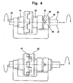
- FIG. 4 shows a detail view of a rotational angle controlled clutch as it finds, for example, for coupling the electric motor with a spring application.
- the coupling is contacted to a first shaft portion (45) of a shaft (47) with a spring (not shown) of a lancing device while a second shaft portion (46) of the shaft is in communication with and driven by an electric motor (not shown) becomes.
- the shaft region (46) is introduced into an interface of the motor (not shown) and rotated by this.
- the shaft portion (46) has at its, not connected to the motor end, a tooth structure (42) which engages in the tooth structure of the opposite end (41) of the shaft portion (45).
- the coupling further includes a link (44) in which the first shaft portion (46) is guided by a pin (43) fixedly connected to the shaft portion (46). If the shaft region (46) experiences a rotation, the bolt (43) is correspondingly guided along the guide (44).
- FIG. 4 thus shows a coupling which, depending on a fixed angle of rotation, which is predetermined by the contour of the gate, a control of the motor and thus the drive unit allowed.
- the bolt (43) of the shaft portion (46) first reaches a position (48) of the link. In this position, the shaft portion (46) undergoes a first axial deflection whereby the motor is stopped. To trigger the stitch, the motor is reactivated by the user. With increasing angle of rotation of the bolt (43) continues to follow the forced guidance through the gate until it reaches the position (49). As a result, the shaft region (46) is deflected to the extent that a decoupling of the shaft ends is achieved as described above.
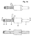
- FIG. 5 shows a torque-controlled clutch, which also finds application as a coupling mechanism between the engine and a spring.
- the torque-controlled clutch consists of a first drive element (52), which has a leaf spring (53).
- Another drive element (51) with pins (54) is rotatably connected to the drive element (52).
- the spring is tensioned by initially rotating the drive element (51) by means of a motor (not shown) while the drive element (52) remains stationary in the system.
- the leaf spring (53) is pressed against the pins (54) and thus bent.
- Figure 5 (f) the torque required and thus the motor current to tension the spring increases, as illustrated in Figure 5 (f).
- the motor current is measured by a drive electronics (not shown) and compared with a set limit.
- a first set limit is reached, the engine is stopped.
- the spring is now fully stretched (s. FIG. 5 d) ,
- the motor is switched on again.
- the torque increases again.
- a second limit value of the clutch which is greater than the first set limit, the positive connection between the leaf spring (53) and the pins (54) dissolves and the spring can run back almost frictionless.
- the released energy is converted to carry out a lancing movement (s. FIG. 5 e) ).
- the applied torque falls back to almost zero as shown in the graph (5f).
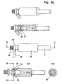
- FIG. 6 shows several embodiments of a clutch wherein a mechanical energy storage in a rotationally offset mass is used.
- a mechanical energy storage in a rotationally offset mass
- gearbox and / or clutches for coupling the engine to the mechanical energy storage can be dispensed with.
- the structure of the system is simplified compared to a structure with a spring as a mechanical energy storage.
- a structural reduction of the drive unit can be achieved. If a moving mass is used as a mechanical energy store, thus, for example, an electric motor can be connected directly to the mass to be accelerated and set in rotation.
- kinetic energy is initially stored by a simple construction.
- the stored energy has to be transferred from the energy store to the lancet body quickly and with low loss in order to carry out a lancing process.
- Such energy transfer can take place via a suitable coupling between mechanical energy storage - here the moving mass - and the lancet.
- the clutch should work as lossless as possible and have small switching times, so that frictional energy losses are minimized.
- two advantageous embodiments are possible, which allow a transfer of energy to the lancet body quickly and with little loss.
- a direct conversion of the kinetic energy to the lancet body or to a mechanical motion converter and thus into a lancing process can take place.
- the z. B. is realized in the form of a spring takes place.
- This has the advantage that when a lancing process is triggered, it is not necessary first to set the mass in rotation in order to provide the necessary energy for the lancing process.
- Such a mechanism would have the consequence that when triggering the lancing process, the user would first have to wait a few seconds until the mass is accelerated accordingly by the electric motor and then an energy transfer can take place.
- a buffer is used in conjunction with a rotating mass, it is possible to temporarily store the energy gained by the rotation in a spring. A triggering of the lancing process by z. B.
- a coupling between the mass and a buffer, or a lancet body makes it possible for a transfer of the kinetic energy to take place abruptly in about 1 ms. This thus allows either a direct conversion of the rotational energy into a piercing movement or an efficient storage of the energy in a buffer, despite a simple construction of the system.
- FIG. 6 a shows an electric motor (9) which is connected to the acceleration of a mass (62) with this and set in rotation.
- the switch button (65) By pressing the switch button (65), the turns of a wrap spring (63) are pressed onto the journal of the rotational mass (62). If the mass is driven by the motor, thereby, the spring (63) abruptly wound on the pin, whereby the shaft (64) experiences an acceleration.
- the rotational movement of the shaft (64) is used to tension the drive spring (66), which is used as an intermediate store, or converted directly into the piercing movement.
- the kinetic energy is first latched by automatically actuating the shift key, compressing the spring (66).
- the spring is relaxed, whereby a lancet body can be driven.
- the motor can be rotated shortly after performing the clamping or the lancing process in the opposite direction.
- necessary for the lancing process steps can be automated so that z. B. upon reaching a predetermined rotational frequency, the shift key (65) is automatically actuated.
- the detachment of the wrap spring and thus the operation of the motor can be initiated in the opposite direction automatically after completion of the lancing operation.
- FIG. 6 b) shows another principle with a Reibrichtsperre that allows transmission of the kinetic energy of a rotating mass to a lancet body.
- Analogous to FIG. 6 a) has the mechanical energy storage in FIG. 6 b) First, an electric motor (9), which accelerates a mass (62). By sliding a switch button (65) there is an axial displacement of the Reibrichtsperre (67). As a result, the clamping webs of Reibrichtsperre (67) pressed against the outer wall of the cone of the rotational mass (62). If there is a jamming of the clamping webs with the mass (62), the Reibrichtsperre is accelerated abruptly and follows the movement of the rotational mass (62).
- the drive principle can be coupled directly to the lancet body or to a buffer.
- the Reibrichtsperre (67) by pushing the switch button (65) pulled out of the cone of the rotational mass (62).
- FIG. 6c shows a further embodiment for coupling a rotating mass to a lancet body or buffer, as already in FIG. 6 a and 6 b, was presented.
- the system has an electric motor (9) which rotationally accelerates a mass (62).
- a switch button (65) By pushing a switch button (65), a sudden engagement of the freewheel shaft (68) with the rotational mass (62) is achieved, so that the kinetic energy of the mass (62) can be transmitted as little loss as possible and directly to the lancet body or a buffer.
- the system has a number of clamping balls (69) which are analogous to those in FIG FIG. 6b introduced principle by pushing the switch button with the cone of the rotational mass (62) are clamped.
- retaining disks (70) prevent the balls (69) from falling out, by which the shaft (63) is coupled to the rotational mass (62).
- the freewheel shaft (68) is forced to follow the movement of the rotating mass (62), transferring energy from the rotating mass to the shaft (69) within a millisecond.
- the coupling connection between the shaft (64) and the rotational mass (62) is also released here by pushing the switch button (65), in that the shaft (64) is pulled out of the cone of the mass.
Landscapes
- Health & Medical Sciences (AREA)
- Life Sciences & Earth Sciences (AREA)
- Molecular Biology (AREA)
- Surgery (AREA)
- Biophysics (AREA)
- Pathology (AREA)
- Engineering & Computer Science (AREA)
- Biomedical Technology (AREA)
- Heart & Thoracic Surgery (AREA)
- Medical Informatics (AREA)
- Hematology (AREA)
- Physics & Mathematics (AREA)
- Animal Behavior & Ethology (AREA)
- General Health & Medical Sciences (AREA)
- Public Health (AREA)
- Veterinary Medicine (AREA)
- Dermatology (AREA)
- Measurement Of The Respiration, Hearing Ability, Form, And Blood Characteristics Of Living Organisms (AREA)
- Measuring Pulse, Heart Rate, Blood Pressure Or Blood Flow (AREA)
- Ultra Sonic Daignosis Equipment (AREA)
Claims (17)
- Aide à la perforation pour générer une ouverture de peau dans une partie de corps comprenant- un boîtier (2) avec une ouverture (4), de laquelle une lancette peut sortir,- une lancette avec un corps de lancette, et- une unité d'entraînement (8) pour l'entraînement du corps de lancette et de la lancette, de sorte que la pointe de lancette peut sortir au moins en partie du boîtier (2) pour exécuter une opération de perforation,- l'unité d'entraînement (8) contenant- un moteur (9), qui peut être mis en contact avec un accumulateur d'énergie électrique, de sorte que de l'énergie est mise à disposition pour l'entraînement de la lancette,- un accumulateur d'énergie mécanique, qui est couplé au moteur en ce sens que l'énergie électrique accumulée par un accumulateur d'énergie électrique est transformée en énergie mécanique et est stockée en moins en partie par l'accumulateur d'énergie mécanique, et- un mécanisme d'accouplement, qui associe le corps de lancette à l'accumulateur d'énergie mécanique, de sorte que l'énergie stockée de l'accumulateur d'énergie peut être transmise au moins en partie au corps de lancette,- le mécanisme d'accouplement contenant un convertisseur de mouvement mécanique, qui dévie l'énergie de l'accumulateur d'énergie sur le corps de lancette en ce sens qu'une commande du mouvement de lancette est convertie dans un mouvement guidé de force, caractérisée en ce que- l'aide à la perforation (1) est intégrée dans un appareil de mesure pour déterminer un analyte à partir d'un échantillon de sang et- le moteur (9) est couplé à une autre fonction de système, indépendant de l'accumulateur d'énergie mécanique, dans l'appareil de mesure.
- Aide à la perforation selon la revendication 1, sur laquelle l'accumulateur d'énergie mécanique est intégré sous forme de corps solide dans l'aide à la perforation.
- Aide à la perforation selon la revendication 1, sur laquelle le convertisseur de mouvement mécanique présente une coulisse de commande (15).
- Aide à la perforation selon la revendication 1, sur laquelle le convertisseur de mouvement mécanique présente un engrenage à passes croisées.
- Aide à la perforation selon l'une des revendications 1-4, sur laquelle le moteur (9) présente un engrenage (10), par lequel le moteur est couplé à l'accumulateur d'énergie.
- Aide à la perforation selon l'une des revendications 1-5, sur laquelle le moteur présente un accouplement (11), par lequel le moteur (9) est couplé à l'accumulateur d'énergie.
- Aide à la perforation selon la revendication 2, sur laquelle l'accumulateur d'énergie mécanique est un ressort (12).
- Aide à la perforation selon la revendication 6, sur laquelle le courant de moteur est mesuré dans l'unité d'entraînement et est comparé avec des valeurs prédéfinies et l'on a une commande du moteur (9) sur la base de cette comparaison.
- Aide à la perforation selon la revendication 6, sur laquelle l'accouplement (11) transmet au moins un couple de 10 mNm à l'accumulateur d'énergie.
- Aide à la perforation selon la revendication 5, sur laquelle l'engrenage (10) est un engrenage conique.
- Aide à la perforation selon la revendication 2, sur laquelle l'accumulateur d'énergie mécanique est une masse (62).
- Aide à la perforation selon la revendication 1, sur laquelle le mécanisme d'accouplement contient un accouplement (11).
- Aide à la perforation selon la revendication 6, sur laquelle l'accouplement est commandé par couple ou angle de rotation.
- Aide à la perforation selon la revendication 1, sur laquelle le moteur électrique (9) est un moteur piézoélectrique ou un moteur à induit extérieur.
- Aide à la perforation selon la revendication 1, sur laquelle l'énergie pour l'accumulateur d'énergie mécanique et l'énergie pour la fonction du système indépendante de l'accumulateur d'énergie sont mises à disposition en même temps ou indépendamment l'une de l'autre.
- Aide à la perforation selon la revendication 1, sur laquelle la fonction du système indépendante de l'accumulateur d'énergie est un transport d'élément de test ou un transport de magasin.
- Aide à la perforation selon la revendication 1, sur laquelle plusieurs éléments de test sont stockés dans un magasin dans l'appareil de mesure.
Priority Applications (2)
| Application Number | Priority Date | Filing Date | Title |
|---|---|---|---|
| EP11001552A EP2335588A1 (fr) | 2004-07-31 | 2005-07-27 | Système de prélèvement sanguin pour le prélèvement de sang à des fins de diagnostic |
| PL05775073T PL1773196T3 (pl) | 2004-07-31 | 2005-07-27 | System do pobierania krwi do pobrania krwi do celów diagnostycznych |
Applications Claiming Priority (2)
| Application Number | Priority Date | Filing Date | Title |
|---|---|---|---|
| DE102004037270A DE102004037270B4 (de) | 2004-07-31 | 2004-07-31 | Blutentnahmesystem zur Entnahme von Blut für Diagnosezwecke |
| PCT/EP2005/008135 WO2006013045A1 (fr) | 2004-07-31 | 2005-07-27 | Systeme de prise de sang a des fins de diagnostic |
Related Child Applications (1)
| Application Number | Title | Priority Date | Filing Date |
|---|---|---|---|
| EP11001552.6 Division-Into | 2011-02-25 |
Publications (2)
| Publication Number | Publication Date |
|---|---|
| EP1773196A1 EP1773196A1 (fr) | 2007-04-18 |
| EP1773196B1 true EP1773196B1 (fr) | 2012-03-21 |
Family
ID=34982381
Family Applications (2)
| Application Number | Title | Priority Date | Filing Date |
|---|---|---|---|
| EP05775073A Expired - Lifetime EP1773196B1 (fr) | 2004-07-31 | 2005-07-27 | Systeme de prise de sang a des fins de diagnostic |
| EP11001552A Withdrawn EP2335588A1 (fr) | 2004-07-31 | 2005-07-27 | Système de prélèvement sanguin pour le prélèvement de sang à des fins de diagnostic |
Family Applications After (1)
| Application Number | Title | Priority Date | Filing Date |
|---|---|---|---|
| EP11001552A Withdrawn EP2335588A1 (fr) | 2004-07-31 | 2005-07-27 | Système de prélèvement sanguin pour le prélèvement de sang à des fins de diagnostic |
Country Status (10)
| Country | Link |
|---|---|
| US (1) | US8075496B2 (fr) |
| EP (2) | EP1773196B1 (fr) |
| JP (1) | JP4922165B2 (fr) |
| CN (1) | CN100548217C (fr) |
| AT (1) | ATE549974T1 (fr) |
| CA (1) | CA2575327C (fr) |
| DE (1) | DE102004037270B4 (fr) |
| ES (1) | ES2383605T3 (fr) |
| PL (1) | PL1773196T3 (fr) |
| WO (1) | WO2006013045A1 (fr) |
Families Citing this family (116)
| Publication number | Priority date | Publication date | Assignee | Title |
|---|---|---|---|---|
| US6391005B1 (en) | 1998-03-30 | 2002-05-21 | Agilent Technologies, Inc. | Apparatus and method for penetration with shaft having a sensor for sensing penetration depth |
| US8641644B2 (en) | 2000-11-21 | 2014-02-04 | Sanofi-Aventis Deutschland Gmbh | Blood testing apparatus having a rotatable cartridge with multiple lancing elements and testing means |
| DE10057832C1 (de) | 2000-11-21 | 2002-02-21 | Hartmann Paul Ag | Blutanalysegerät |
| US8337419B2 (en) | 2002-04-19 | 2012-12-25 | Sanofi-Aventis Deutschland Gmbh | Tissue penetration device |
| US9795747B2 (en) | 2010-06-02 | 2017-10-24 | Sanofi-Aventis Deutschland Gmbh | Methods and apparatus for lancet actuation |
| ATE485766T1 (de) | 2001-06-12 | 2010-11-15 | Pelikan Technologies Inc | Elektrisches betätigungselement für eine lanzette |
| CA2448681C (fr) | 2001-06-12 | 2014-09-09 | Pelikan Technologies, Inc. | Systeme integre de prelevement et d'analyse d'echantillons sanguins avec module de prelevement a utilisation multiple |
| US7041068B2 (en) | 2001-06-12 | 2006-05-09 | Pelikan Technologies, Inc. | Sampling module device and method |
| ES2336081T3 (es) | 2001-06-12 | 2010-04-08 | Pelikan Technologies Inc. | Dispositivo de puncion de auto-optimizacion con medios de adaptacion a variaciones temporales en las propiedades cutaneas. |
| US9226699B2 (en) | 2002-04-19 | 2016-01-05 | Sanofi-Aventis Deutschland Gmbh | Body fluid sampling module with a continuous compression tissue interface surface |
| US9427532B2 (en) | 2001-06-12 | 2016-08-30 | Sanofi-Aventis Deutschland Gmbh | Tissue penetration device |
| AU2002348683A1 (en) | 2001-06-12 | 2002-12-23 | Pelikan Technologies, Inc. | Method and apparatus for lancet launching device integrated onto a blood-sampling cartridge |
| US7981056B2 (en) | 2002-04-19 | 2011-07-19 | Pelikan Technologies, Inc. | Methods and apparatus for lancet actuation |
| US7344894B2 (en) | 2001-10-16 | 2008-03-18 | Agilent Technologies, Inc. | Thermal regulation of fluidic samples within a diagnostic cartridge |
| JP4260024B2 (ja) | 2002-03-19 | 2009-04-30 | バード ダブリン アイティーシー リミティッド | 真空生検装置 |
| AU2003218696A1 (en) | 2002-03-19 | 2003-09-29 | Bard Dublin Itc Limited | Biopsy device and biopsy needle module that can be inserted into the biopsy device |
| US7226461B2 (en) | 2002-04-19 | 2007-06-05 | Pelikan Technologies, Inc. | Method and apparatus for a multi-use body fluid sampling device with sterility barrier release |
| US7141058B2 (en) | 2002-04-19 | 2006-11-28 | Pelikan Technologies, Inc. | Method and apparatus for a body fluid sampling device using illumination |
| US9795334B2 (en) | 2002-04-19 | 2017-10-24 | Sanofi-Aventis Deutschland Gmbh | Method and apparatus for penetrating tissue |
| US8702624B2 (en) | 2006-09-29 | 2014-04-22 | Sanofi-Aventis Deutschland Gmbh | Analyte measurement device with a single shot actuator |
| US8372016B2 (en) | 2002-04-19 | 2013-02-12 | Sanofi-Aventis Deutschland Gmbh | Method and apparatus for body fluid sampling and analyte sensing |
| US7175642B2 (en) | 2002-04-19 | 2007-02-13 | Pelikan Technologies, Inc. | Methods and apparatus for lancet actuation |
| US8221334B2 (en) | 2002-04-19 | 2012-07-17 | Sanofi-Aventis Deutschland Gmbh | Method and apparatus for penetrating tissue |
| US8579831B2 (en) | 2002-04-19 | 2013-11-12 | Sanofi-Aventis Deutschland Gmbh | Method and apparatus for penetrating tissue |
| US7524293B2 (en) | 2002-04-19 | 2009-04-28 | Pelikan Technologies, Inc. | Method and apparatus for penetrating tissue |
| US7229458B2 (en) | 2002-04-19 | 2007-06-12 | Pelikan Technologies, Inc. | Method and apparatus for penetrating tissue |
| US9314194B2 (en) | 2002-04-19 | 2016-04-19 | Sanofi-Aventis Deutschland Gmbh | Tissue penetration device |
| US7491178B2 (en) | 2002-04-19 | 2009-02-17 | Pelikan Technologies, Inc. | Method and apparatus for penetrating tissue |
| US7892183B2 (en) | 2002-04-19 | 2011-02-22 | Pelikan Technologies, Inc. | Method and apparatus for body fluid sampling and analyte sensing |
| US8784335B2 (en) | 2002-04-19 | 2014-07-22 | Sanofi-Aventis Deutschland Gmbh | Body fluid sampling device with a capacitive sensor |
| US7976476B2 (en) | 2002-04-19 | 2011-07-12 | Pelikan Technologies, Inc. | Device and method for variable speed lancet |
| US7582099B2 (en) | 2002-04-19 | 2009-09-01 | Pelikan Technologies, Inc | Method and apparatus for penetrating tissue |
| US7901362B2 (en) | 2002-04-19 | 2011-03-08 | Pelikan Technologies, Inc. | Method and apparatus for penetrating tissue |
| US7674232B2 (en) | 2002-04-19 | 2010-03-09 | Pelikan Technologies, Inc. | Method and apparatus for penetrating tissue |
| US7374544B2 (en) | 2002-04-19 | 2008-05-20 | Pelikan Technologies, Inc. | Method and apparatus for penetrating tissue |
| US7481776B2 (en) | 2002-04-19 | 2009-01-27 | Pelikan Technologies, Inc. | Method and apparatus for penetrating tissue |
| US7547287B2 (en) | 2002-04-19 | 2009-06-16 | Pelikan Technologies, Inc. | Method and apparatus for penetrating tissue |
| US7331931B2 (en) | 2002-04-19 | 2008-02-19 | Pelikan Technologies, Inc. | Method and apparatus for penetrating tissue |
| US9248267B2 (en) | 2002-04-19 | 2016-02-02 | Sanofi-Aventis Deustchland Gmbh | Tissue penetration device |
| US7232451B2 (en) | 2002-04-19 | 2007-06-19 | Pelikan Technologies, Inc. | Method and apparatus for penetrating tissue |
| US8267870B2 (en) | 2002-04-19 | 2012-09-18 | Sanofi-Aventis Deutschland Gmbh | Method and apparatus for body fluid sampling with hybrid actuation |
| US8360992B2 (en) | 2002-04-19 | 2013-01-29 | Sanofi-Aventis Deutschland Gmbh | Method and apparatus for penetrating tissue |
| US7410468B2 (en) | 2002-04-19 | 2008-08-12 | Pelikan Technologies, Inc. | Method and apparatus for penetrating tissue |
| US7909778B2 (en) | 2002-04-19 | 2011-03-22 | Pelikan Technologies, Inc. | Method and apparatus for penetrating tissue |
| US7563232B2 (en) | 2002-04-19 | 2009-07-21 | Pelikan Technologies, Inc. | Method and apparatus for penetrating tissue |
| US7297122B2 (en) | 2002-04-19 | 2007-11-20 | Pelikan Technologies, Inc. | Method and apparatus for penetrating tissue |
| US8574895B2 (en) | 2002-12-30 | 2013-11-05 | Sanofi-Aventis Deutschland Gmbh | Method and apparatus using optical techniques to measure analyte levels |
| DE10314240B4 (de) | 2003-03-29 | 2025-05-28 | Bard Dublin Itc Ltd. | Druckerzeugungseinheit |
| EP1628567B1 (fr) | 2003-05-30 | 2010-08-04 | Pelikan Technologies Inc. | Procede et appareil pour injection de fluide |
| EP1633235B1 (fr) | 2003-06-06 | 2014-05-21 | Sanofi-Aventis Deutschland GmbH | Appareil d'echantillonnage de fluides anatomiques et d'examen de l'analysat |
| WO2006001797A1 (fr) | 2004-06-14 | 2006-01-05 | Pelikan Technologies, Inc. | Element penetrant peu douloureux |
| US7604592B2 (en) | 2003-06-13 | 2009-10-20 | Pelikan Technologies, Inc. | Method and apparatus for a point of care device |
| EP1671096A4 (fr) | 2003-09-29 | 2009-09-16 | Pelikan Technologies Inc | Procede et appareil permettant d'obtenir un dispositif de capture d'echantillons ameliore |
| US9351680B2 (en) | 2003-10-14 | 2016-05-31 | Sanofi-Aventis Deutschland Gmbh | Method and apparatus for a variable user interface |
| US7822454B1 (en) | 2005-01-03 | 2010-10-26 | Pelikan Technologies, Inc. | Fluid sampling device with improved analyte detecting member configuration |
| EP1706026B1 (fr) | 2003-12-31 | 2017-03-01 | Sanofi-Aventis Deutschland GmbH | Procédé et appareil permettant d'améliorer le flux fluidique et le prélèvement d'échantillons |
| WO2006011062A2 (fr) | 2004-05-20 | 2006-02-02 | Albatros Technologies Gmbh & Co. Kg | Hydrogel imprimable pour biocapteurs |
| US9775553B2 (en) | 2004-06-03 | 2017-10-03 | Sanofi-Aventis Deutschland Gmbh | Method and apparatus for a fluid sampling device |
| WO2005120365A1 (fr) | 2004-06-03 | 2005-12-22 | Pelikan Technologies, Inc. | Procede et appareil pour la fabrication d'un dispositif d'echantillonnage de liquides |
| EP1768571B1 (fr) | 2004-07-09 | 2012-03-21 | Bard Peripheral Vascular, Inc. | Systeme de tir pour dispositif de biopsie |
| US8652831B2 (en) | 2004-12-30 | 2014-02-18 | Sanofi-Aventis Deutschland Gmbh | Method and apparatus for analyte measurement test time |
| USD567938S1 (en) * | 2005-01-28 | 2008-04-29 | Matsushita Electric Industrial Co., Ltd. | Puncture device |
| US7517321B2 (en) | 2005-01-31 | 2009-04-14 | C. R. Bard, Inc. | Quick cycle biopsy system |
| DE102005004498B4 (de) | 2005-02-01 | 2009-07-09 | Roche Diagnostics Gmbh | Antrieb für medizinische Geräte und Verwendung für einen solchen Antrieb |
| DE102005005017A1 (de) * | 2005-02-03 | 2006-08-17 | Roche Diagnostics Gmbh | Elektromechanische Stechhilfe zur Gewinnung flüssiger Proben |
| JP4955681B2 (ja) | 2005-08-10 | 2012-06-20 | シー・アール・バード・インコーポレーテッド | 直線駆動装置を有する単一挿入複数サンプリング生検デバイス |
| US8267868B2 (en) | 2005-08-10 | 2012-09-18 | C. R. Bard, Inc. | Single-insertion, multiple sample biopsy device with integrated markers |
| WO2007021904A2 (fr) | 2005-08-10 | 2007-02-22 | C.R. Bard Inc. | Dispositif de biopsie a echantillonnage multiple et introduction unique compatible avec divers systemes de transport et marqueurs integres |
| US8251917B2 (en) | 2006-08-21 | 2012-08-28 | C. R. Bard, Inc. | Self-contained handheld biopsy needle |
| ATE493074T1 (de) | 2006-10-06 | 2011-01-15 | Bard Peripheral Vascular Inc | Gewebehandhabungssystem mit verringerter exposition der bedienungsperson |
| EP1917909A1 (fr) | 2006-10-12 | 2008-05-07 | Roche Diagnostics GmbH | Dispositif et procédé pour l'extraction d'échantillon liquides |
| EP3714798A3 (fr) | 2006-10-24 | 2020-12-16 | C. R. Bard, Inc. | Aiguille de biopsie à rapport d'aspect faible pour grand échantillon |
| EP1972275B1 (fr) * | 2007-03-20 | 2015-10-28 | Roche Diagnostics GmbH | Système destiné à la mesure in vivo d'une concentration d'un analyte |
| PL1992283T3 (pl) | 2007-05-16 | 2011-04-29 | Hoffmann La Roche | System nakłuwający |
| WO2008145625A2 (fr) | 2007-05-29 | 2008-12-04 | Roche Diagnostics Gmbh | Système de test visant à mesurer la concentration d'un analyte dans un fluide corporel |
| US10219832B2 (en) | 2007-06-29 | 2019-03-05 | Actuated Medical, Inc. | Device and method for less forceful tissue puncture |
| US9987468B2 (en) | 2007-06-29 | 2018-06-05 | Actuated Medical, Inc. | Reduced force device for intravascular access and guidewire placement |
| GB2451840B (en) * | 2007-08-14 | 2012-01-18 | Owen Mumford Ltd | Lancing devices |
| BRPI0816471B8 (pt) * | 2007-08-29 | 2021-06-22 | Brighter Ab | aparelho médico portátil |
| EP2039293A1 (fr) | 2007-09-19 | 2009-03-25 | F. Hoffman-la Roche AG | Entraînement de combinaison pour un système d'obtention d'échantillons pour obtenir un échantillon liquide |
| ATE484379T1 (de) | 2007-10-29 | 2010-10-15 | Hoffmann La Roche | Verfahren zur herstellung von bandware mit diagnostischen hilfsmitteln |
| US8241225B2 (en) | 2007-12-20 | 2012-08-14 | C. R. Bard, Inc. | Biopsy device |
| US7854706B2 (en) | 2007-12-27 | 2010-12-21 | Devicor Medical Products, Inc. | Clutch and valving system for tetherless biopsy device |
| US7766846B2 (en) * | 2008-01-28 | 2010-08-03 | Roche Diagnostics Operations, Inc. | Rapid blood expression and sampling |
| AU2013202929B2 (en) * | 2008-01-28 | 2016-05-26 | F. Hoffmann-La Roche Ag | System for detection of an analyte in a body fluid |
| WO2009126900A1 (fr) | 2008-04-11 | 2009-10-15 | Pelikan Technologies, Inc. | Procédé et appareil pour dispositif de détection d’analyte |
| US9375169B2 (en) | 2009-01-30 | 2016-06-28 | Sanofi-Aventis Deutschland Gmbh | Cam drive for managing disposable penetrating member actions with a single motor and motor and control system |
| WO2010107424A1 (fr) | 2009-03-16 | 2010-09-23 | C.R. Bard, Inc. | Dispositif de biopsie comprenant une coupe rotative |
| ES2690737T3 (es) | 2009-04-15 | 2018-11-22 | C.R. Bard Inc. | Gestión de fluido |
| ES2391063T3 (es) | 2009-04-22 | 2012-11-21 | F. Hoffmann-La Roche Ag | Fabricación de un material en forma de banda, con medios de diagnóstico |
| US8206316B2 (en) | 2009-06-12 | 2012-06-26 | Devicor Medical Products, Inc. | Tetherless biopsy device with reusable portion |
| EP2279689A1 (fr) * | 2009-07-30 | 2011-02-02 | F. Hoffmann-La Roche AG | Appareil médical portatif |
| EP2464294B1 (fr) | 2009-08-12 | 2019-10-02 | C.R. Bard Inc. | Appareil de biopsie comprenant un mécanisme à molette intégré qui permet de faire tourner manuellement une canule pour biopsie |
| US8430824B2 (en) * | 2009-10-29 | 2013-04-30 | Bard Peripheral Vascular, Inc. | Biopsy driver assembly having a control circuit for conserving battery power |
| US8283890B2 (en) | 2009-09-25 | 2012-10-09 | Bard Peripheral Vascular, Inc. | Charging station for battery powered biopsy apparatus |
| US8485989B2 (en) | 2009-09-01 | 2013-07-16 | Bard Peripheral Vascular, Inc. | Biopsy apparatus having a tissue sample retrieval mechanism |
| US8597206B2 (en) | 2009-10-12 | 2013-12-03 | Bard Peripheral Vascular, Inc. | Biopsy probe assembly having a mechanism to prevent misalignment of components prior to installation |
| US8965476B2 (en) | 2010-04-16 | 2015-02-24 | Sanofi-Aventis Deutschland Gmbh | Tissue penetration device |
| EP2613701A2 (fr) * | 2010-09-07 | 2013-07-17 | Innova Medical Design LLC | Systèmes, procédés et dispositifs de réduction de la douleur provoquée par une surveillance de glucose et une administration d'insuline chez des patients diabétiques |
| DE102011056626B4 (de) * | 2011-12-19 | 2014-02-13 | Gerresheimer Regensburg Gmbh | Stechhilfevorrichtung zur Blutprobenentnahme |
| CN102813521A (zh) * | 2012-08-13 | 2012-12-12 | 汪桂霞 | 自动检验采血器 |
| ES2875575T3 (es) | 2013-03-20 | 2021-11-10 | Bard Peripheral Vascular Inc | Dispositivo de biopsia |
| CA3005826C (fr) | 2013-04-15 | 2021-11-23 | Becton, Dickinson And Company | Dispositif de collecte de fluide biologique et separation de fluide biologique et systeme d'essai |
| JP6101400B2 (ja) | 2013-04-15 | 2017-03-22 | ベクトン・ディキンソン・アンド・カンパニーBecton, Dickinson And Company | 血液サンプリング移送デバイスならびに血液分離および検査実施システム |
| WO2015061643A2 (fr) * | 2013-10-25 | 2015-04-30 | Actuated Medical, Inc. | Dispositif et procédé pour perforation de tissu moins puissante |
| EP3549533B1 (fr) | 2013-11-05 | 2020-12-30 | C.R. Bard, Inc. | Dispositif de biopsie doté d'un vide intégré |
| JP6636136B2 (ja) | 2015-05-01 | 2020-01-29 | シー・アール・バード・インコーポレーテッドC R Bard Incorporated | 生検装置 |
| US10940292B2 (en) | 2015-07-08 | 2021-03-09 | Actuated Medical, Inc. | Reduced force device for intravascular access and guidewire placement |
| US11793543B2 (en) | 2015-09-18 | 2023-10-24 | Obvius Robotics, Inc. | Device and method for automated insertion of penetrating member |
| CN106175797B (zh) * | 2016-07-18 | 2022-10-28 | 湖南千山制药机械股份有限公司 | 采血针针尖角度调整装置 |
| US11844500B2 (en) | 2017-05-19 | 2023-12-19 | Merit Medical Systems, Inc. | Semi-automatic biopsy needle device and methods of use |
| WO2018213580A1 (fr) | 2017-05-19 | 2018-11-22 | Merit Medical Systems, Inc. | Aiguille de biopsie rotative |
| EP3624697B1 (fr) | 2017-05-19 | 2024-02-14 | Merit Medical Systems, Inc. | Dispositifs aiguilles de biopsie et leurs procédés d'utilisation |
| US12295556B2 (en) | 2019-09-27 | 2025-05-13 | Merit Medical Systems, Inc. | Rotation biopsy system and handle |
| US12150627B2 (en) | 2019-12-11 | 2024-11-26 | Merit Medical Systems, Inc. | Bone biopsy device and related methods |
| US12426965B2 (en) | 2023-06-15 | 2025-09-30 | Obvius Robotics, Inc. | Image-guided robotic arm for inserting a penetrating member into a body lumen |
Family Cites Families (30)
| Publication number | Priority date | Publication date | Assignee | Title |
|---|---|---|---|---|
| JPS521991A (en) * | 1975-06-24 | 1977-01-08 | Nikkiso Co Ltd | Blood pump |
| DE4212315A1 (de) * | 1992-04-13 | 1993-10-14 | Boehringer Mannheim Gmbh | Blutlanzettenvorrichtung zur Entnahme von Blut für Diagnosezwecke |
| JPH0614889A (ja) * | 1992-07-03 | 1994-01-25 | Omron Corp | 血圧測定用カフ自動巻付装置 |
| JPH06148892A (ja) | 1992-11-06 | 1994-05-27 | Fuji Photo Film Co Ltd | 画像転写用感光材料 |
| US5464418A (en) * | 1993-12-09 | 1995-11-07 | Schraga; Steven | Reusable lancet device |
| US5797942A (en) * | 1996-09-23 | 1998-08-25 | Schraga; Steven | Re-usable end cap for re-usable lancet devices for removing and disposing of a contaminated lancet |
| JP3177463B2 (ja) * | 1996-10-25 | 2001-06-18 | 学校法人桐蔭学園 | 関節拘縮用治療装置 |
| US6093156A (en) * | 1996-12-06 | 2000-07-25 | Abbott Laboratories | Method and apparatus for obtaining blood for diagnostic tests |
| US5908434A (en) * | 1998-02-13 | 1999-06-01 | Schraga; Steven | Lancet device |
| US6210420B1 (en) * | 1999-01-19 | 2001-04-03 | Agilent Technologies, Inc. | Apparatus and method for efficient blood sampling with lancet |
| DE19909602A1 (de) * | 1999-03-05 | 2000-09-07 | Roche Diagnostics Gmbh | Gerät zur Entnahme von Blut für Diagnosezwecke |
| DE19948759A1 (de) * | 1999-10-09 | 2001-04-12 | Roche Diagnostics Gmbh | Blutlanzettenvorrichtung zur Entnahme von Blut für Diagnosezwecke |
| EP1238632B1 (fr) | 1999-12-13 | 2011-05-11 | ARKRAY, Inc. | Appareil de mesure pour fluide corporel pourvu d'une lancette, et porte-lancette utilise avec ledit appareil de mesure |
| JP4129612B2 (ja) * | 2000-01-31 | 2008-08-06 | 株式会社デンソー | 蓄圧式燃料供給装置 |
| US6540675B2 (en) * | 2000-06-27 | 2003-04-01 | Rosedale Medical, Inc. | Analyte monitor |
| DE10047419A1 (de) * | 2000-09-26 | 2002-04-11 | Roche Diagnostics Gmbh | Lanzettensystem |
| DE10057832C1 (de) * | 2000-11-21 | 2002-02-21 | Hartmann Paul Ag | Blutanalysegerät |
| US6530892B1 (en) * | 2001-03-07 | 2003-03-11 | Helen V. Kelly | Automatic skin puncturing system |
| EP1328192B1 (fr) | 2001-03-29 | 2011-01-05 | Lifescan Scotland Ltd | Appareil d'analyse d'echantillon integre |
| ATE485766T1 (de) * | 2001-06-12 | 2010-11-15 | Pelikan Technologies Inc | Elektrisches betätigungselement für eine lanzette |
| ES2336081T3 (es) * | 2001-06-12 | 2010-04-08 | Pelikan Technologies Inc. | Dispositivo de puncion de auto-optimizacion con medios de adaptacion a variaciones temporales en las propiedades cutaneas. |
| ATE497731T1 (de) * | 2001-06-12 | 2011-02-15 | Pelikan Technologies Inc | Gerät zur erhöhung der erfolgsrate im hinblick auf die durch einen fingerstich erhaltene blutausbeute |
| DE20213607U1 (de) * | 2002-02-21 | 2003-07-03 | Paul Hartmann AG, 89522 Heidenheim | Blutanalysegerät zur Bestimmung eines Analyten |
| US7892183B2 (en) * | 2002-04-19 | 2011-02-22 | Pelikan Technologies, Inc. | Method and apparatus for body fluid sampling and analyte sensing |
| US8267870B2 (en) * | 2002-04-19 | 2012-09-18 | Sanofi-Aventis Deutschland Gmbh | Method and apparatus for body fluid sampling with hybrid actuation |
| DE10223558A1 (de) * | 2002-05-28 | 2003-12-11 | Roche Diagnostics Gmbh | Blutentnahmesystem |
| US7572237B2 (en) * | 2002-11-06 | 2009-08-11 | Abbott Diabetes Care Inc. | Automatic biological analyte testing meter with integrated lancing device and methods of use |
| EP1581115B1 (fr) * | 2002-12-30 | 2009-10-14 | Roche Diagnostics GmbH | Systeme de suspension d'acquisition du sang |
| AU2003300940A1 (en) * | 2002-12-30 | 2004-07-29 | Hoffmann-La Roche Ag | Flexible test strip lancet device |
| DE10336933B4 (de) | 2003-08-07 | 2007-04-26 | Roche Diagnostics Gmbh | Blutentnahmesystem |
-
2004
- 2004-07-31 DE DE102004037270A patent/DE102004037270B4/de not_active Expired - Fee Related
-
2005
- 2005-07-27 JP JP2007523007A patent/JP4922165B2/ja not_active Expired - Fee Related
- 2005-07-27 CN CNB2005800259706A patent/CN100548217C/zh not_active Expired - Fee Related
- 2005-07-27 PL PL05775073T patent/PL1773196T3/pl unknown
- 2005-07-27 EP EP05775073A patent/EP1773196B1/fr not_active Expired - Lifetime
- 2005-07-27 ES ES05775073T patent/ES2383605T3/es not_active Expired - Lifetime
- 2005-07-27 CA CA2575327A patent/CA2575327C/fr not_active Expired - Fee Related
- 2005-07-27 WO PCT/EP2005/008135 patent/WO2006013045A1/fr not_active Ceased
- 2005-07-27 AT AT05775073T patent/ATE549974T1/de active
- 2005-07-27 EP EP11001552A patent/EP2335588A1/fr not_active Withdrawn
-
2007
- 2007-01-27 US US11/627,954 patent/US8075496B2/en not_active Expired - Fee Related
Also Published As
| Publication number | Publication date |
|---|---|
| JP4922165B2 (ja) | 2012-04-25 |
| US8075496B2 (en) | 2011-12-13 |
| ES2383605T3 (es) | 2012-06-22 |
| WO2006013045A1 (fr) | 2006-02-09 |
| PL1773196T3 (pl) | 2012-09-28 |
| DE102004037270B4 (de) | 2008-01-31 |
| CA2575327C (fr) | 2012-01-03 |
| JP2008508005A (ja) | 2008-03-21 |
| EP1773196A1 (fr) | 2007-04-18 |
| DE102004037270A1 (de) | 2006-03-23 |
| CN100548217C (zh) | 2009-10-14 |
| CN1993079A (zh) | 2007-07-04 |
| HK1107921A1 (zh) | 2008-04-25 |
| CA2575327A1 (fr) | 2006-02-09 |
| ATE549974T1 (de) | 2012-04-15 |
| US20070219572A1 (en) | 2007-09-20 |
| EP2335588A1 (fr) | 2011-06-22 |
Similar Documents
| Publication | Publication Date | Title |
|---|---|---|
| EP1773196B1 (fr) | Systeme de prise de sang a des fins de diagnostic | |
| EP2213229B1 (fr) | Système de prise de sang | |
| JP2008508005A5 (fr) | ||
| EP2606823B1 (fr) | Système de prélèvement du sang | |
| EP1808128B1 (fr) | Dispositif auxiliaire de piqûre avec protection contre réutilisation | |
| DE102005004498B4 (de) | Antrieb für medizinische Geräte und Verwendung für einen solchen Antrieb | |
| EP2205154B1 (fr) | Magasin a lancettes | |
| EP1254632B1 (fr) | Lancette de prélèvement sanguin avec un mécanisme de pivot | |
| EP1034740B1 (fr) | Appareil de prélèvement de sang à but diagnostique | |
| EP2039293A1 (fr) | Entraînement de combinaison pour un système d'obtention d'échantillons pour obtenir un échantillon liquide | |
| EP1884191A1 (fr) | Système a piquer la peau | |
| EP1865846A2 (fr) | Systeme de piqure destine au prelevement d'un liquide organique | |
| DE102004059491A1 (de) | Lanzettenvorrichtung zum Erzeugen einer Einstichwunde und Lanzettenantriebs-Baugruppe | |
| EP2311373B1 (fr) | Système de piqûre pour l'extraction d'un liquide corporel | |
| EP2193746B1 (fr) | Appareil destiné à la production d'un échantillon de sang | |
| DE202009003050U1 (de) | Nadel-Einstichvorrichtung für medizinische Geräte | |
| EP2563223B1 (fr) | Aide à la plantation dotée d'un déclenchement automatique | |
| EP2823762B1 (fr) | Actionneur de piquage | |
| DE102009055874A1 (de) | Einfach betätigbare Stechhilfe |
Legal Events
| Date | Code | Title | Description |
|---|---|---|---|
| PUAI | Public reference made under article 153(3) epc to a published international application that has entered the european phase |
Free format text: ORIGINAL CODE: 0009012 |
|
| 17P | Request for examination filed |
Effective date: 20070228 |
|
| AK | Designated contracting states |
Kind code of ref document: A1 Designated state(s): AT BE BG CH CY CZ DE DK EE ES FI FR GB GR HU IE IS IT LI LT LU LV MC NL PL PT RO SE SI SK TR |
|
| RIN1 | Information on inventor provided before grant (corrected) |
Inventor name: WINHEIM, SVEN Inventor name: SCHULAT, JOCHEN Inventor name: HOERAUF, CHRISTIAN Inventor name: SCHERER, JOERG Inventor name: THOES, BRUNO Inventor name: SCHMELZEIZEN-REDEKER, GUENTHER Inventor name: SCHMID, WILFRIED Inventor name: PACHL, RUDOLF Inventor name: DOEPPER, JOACHIM Inventor name: RASCH-MENGES, JUERGEN Inventor name: DECK, FRANK |
|
| DAX | Request for extension of the european patent (deleted) | ||
| 17Q | First examination report despatched |
Effective date: 20090407 |
|
| REG | Reference to a national code |
Ref country code: DE Ref legal event code: R079 Ref document number: 502005012551 Country of ref document: DE Free format text: PREVIOUS MAIN CLASS: A61B0005150000 Ipc: A61B0005151000 |
|
| GRAP | Despatch of communication of intention to grant a patent |
Free format text: ORIGINAL CODE: EPIDOSNIGR1 |
|
| RIC1 | Information provided on ipc code assigned before grant |
Ipc: A61B 5/157 20060101ALI20110829BHEP Ipc: A61B 5/151 20060101AFI20110829BHEP |
|
| GRAS | Grant fee paid |
Free format text: ORIGINAL CODE: EPIDOSNIGR3 |
|
| GRAA | (expected) grant |
Free format text: ORIGINAL CODE: 0009210 |
|
| AK | Designated contracting states |
Kind code of ref document: B1 Designated state(s): AT BE BG CH CY CZ DE DK EE ES FI FR GB GR HU IE IS IT LI LT LU LV MC NL PL PT RO SE SI SK TR |
|
| REG | Reference to a national code |
Ref country code: GB Ref legal event code: FG4D Free format text: NOT ENGLISH |
|
| REG | Reference to a national code |
Ref country code: DE Ref legal event code: R081 Ref document number: 502005012551 Country of ref document: DE Owner name: ROCHE DIABETES CARE GMBH, DE Free format text: FORMER OWNERS: ROCHE DIAGNOSTICS GMBH, 68305 MANNHEIM, DE; F. HOFFMANN-LA ROCHE AG, 4070 BASEL, CH |
|
| REG | Reference to a national code |
Ref country code: CH Ref legal event code: EP |
|
| REG | Reference to a national code |
Ref country code: IE Ref legal event code: FG4D Free format text: LANGUAGE OF EP DOCUMENT: GERMAN |
|
| REG | Reference to a national code |
Ref country code: AT Ref legal event code: REF Ref document number: 549974 Country of ref document: AT Kind code of ref document: T Effective date: 20120415 |
|
| REG | Reference to a national code |
Ref country code: DE Ref legal event code: R096 Ref document number: 502005012551 Country of ref document: DE Effective date: 20120516 |
|
| REG | Reference to a national code |
Ref country code: ES Ref legal event code: FG2A Ref document number: 2383605 Country of ref document: ES Kind code of ref document: T3 Effective date: 20120622 |
|
| REG | Reference to a national code |
Ref country code: NL Ref legal event code: T3 |
|
| PG25 | Lapsed in a contracting state [announced via postgrant information from national office to epo] |
Ref country code: LT Free format text: LAPSE BECAUSE OF FAILURE TO SUBMIT A TRANSLATION OF THE DESCRIPTION OR TO PAY THE FEE WITHIN THE PRESCRIBED TIME-LIMIT Effective date: 20120321 |
|
| LTIE | Lt: invalidation of european patent or patent extension |
Effective date: 20120321 |
|
| PG25 | Lapsed in a contracting state [announced via postgrant information from national office to epo] |
Ref country code: LV Free format text: LAPSE BECAUSE OF FAILURE TO SUBMIT A TRANSLATION OF THE DESCRIPTION OR TO PAY THE FEE WITHIN THE PRESCRIBED TIME-LIMIT Effective date: 20120321 Ref country code: GR Free format text: LAPSE BECAUSE OF FAILURE TO SUBMIT A TRANSLATION OF THE DESCRIPTION OR TO PAY THE FEE WITHIN THE PRESCRIBED TIME-LIMIT Effective date: 20120622 Ref country code: FI Free format text: LAPSE BECAUSE OF FAILURE TO SUBMIT A TRANSLATION OF THE DESCRIPTION OR TO PAY THE FEE WITHIN THE PRESCRIBED TIME-LIMIT Effective date: 20120321 |
|
| PG25 | Lapsed in a contracting state [announced via postgrant information from national office to epo] |
Ref country code: CY Free format text: LAPSE BECAUSE OF FAILURE TO SUBMIT A TRANSLATION OF THE DESCRIPTION OR TO PAY THE FEE WITHIN THE PRESCRIBED TIME-LIMIT Effective date: 20120321 |
|
| REG | Reference to a national code |
Ref country code: PL Ref legal event code: T3 |
|
| PG25 | Lapsed in a contracting state [announced via postgrant information from national office to epo] |
Ref country code: IS Free format text: LAPSE BECAUSE OF FAILURE TO SUBMIT A TRANSLATION OF THE DESCRIPTION OR TO PAY THE FEE WITHIN THE PRESCRIBED TIME-LIMIT Effective date: 20120721 Ref country code: RO Free format text: LAPSE BECAUSE OF FAILURE TO SUBMIT A TRANSLATION OF THE DESCRIPTION OR TO PAY THE FEE WITHIN THE PRESCRIBED TIME-LIMIT Effective date: 20120321 Ref country code: EE Free format text: LAPSE BECAUSE OF FAILURE TO SUBMIT A TRANSLATION OF THE DESCRIPTION OR TO PAY THE FEE WITHIN THE PRESCRIBED TIME-LIMIT Effective date: 20120321 Ref country code: SI Free format text: LAPSE BECAUSE OF FAILURE TO SUBMIT A TRANSLATION OF THE DESCRIPTION OR TO PAY THE FEE WITHIN THE PRESCRIBED TIME-LIMIT Effective date: 20120321 Ref country code: CZ Free format text: LAPSE BECAUSE OF FAILURE TO SUBMIT A TRANSLATION OF THE DESCRIPTION OR TO PAY THE FEE WITHIN THE PRESCRIBED TIME-LIMIT Effective date: 20120321 Ref country code: SE Free format text: LAPSE BECAUSE OF FAILURE TO SUBMIT A TRANSLATION OF THE DESCRIPTION OR TO PAY THE FEE WITHIN THE PRESCRIBED TIME-LIMIT Effective date: 20120321 |
|
| PG25 | Lapsed in a contracting state [announced via postgrant information from national office to epo] |
Ref country code: SK Free format text: LAPSE BECAUSE OF FAILURE TO SUBMIT A TRANSLATION OF THE DESCRIPTION OR TO PAY THE FEE WITHIN THE PRESCRIBED TIME-LIMIT Effective date: 20120321 Ref country code: PT Free format text: LAPSE BECAUSE OF FAILURE TO SUBMIT A TRANSLATION OF THE DESCRIPTION OR TO PAY THE FEE WITHIN THE PRESCRIBED TIME-LIMIT Effective date: 20120723 |
|
| PLBE | No opposition filed within time limit |
Free format text: ORIGINAL CODE: 0009261 |
|
| STAA | Information on the status of an ep patent application or granted ep patent |
Free format text: STATUS: NO OPPOSITION FILED WITHIN TIME LIMIT |
|
| BERE | Be: lapsed |
Owner name: ROCHE DIAGNOSTICS G.M.B.H. Effective date: 20120731 Owner name: F. HOFFMANN-LA ROCHE A.G. Effective date: 20120731 |
|
| PG25 | Lapsed in a contracting state [announced via postgrant information from national office to epo] |
Ref country code: DK Free format text: LAPSE BECAUSE OF FAILURE TO SUBMIT A TRANSLATION OF THE DESCRIPTION OR TO PAY THE FEE WITHIN THE PRESCRIBED TIME-LIMIT Effective date: 20120321 |
|
| 26N | No opposition filed |
Effective date: 20130102 |
|
| PG25 | Lapsed in a contracting state [announced via postgrant information from national office to epo] |
Ref country code: MC Free format text: LAPSE BECAUSE OF NON-PAYMENT OF DUE FEES Effective date: 20120731 |
|
| REG | Reference to a national code |
Ref country code: CH Ref legal event code: PL |
|
| REG | Reference to a national code |
Ref country code: DE Ref legal event code: R097 Ref document number: 502005012551 Country of ref document: DE Effective date: 20130102 |
|
| PG25 | Lapsed in a contracting state [announced via postgrant information from national office to epo] |
Ref country code: CH Free format text: LAPSE BECAUSE OF NON-PAYMENT OF DUE FEES Effective date: 20120731 Ref country code: LI Free format text: LAPSE BECAUSE OF NON-PAYMENT OF DUE FEES Effective date: 20120731 |
|
| REG | Reference to a national code |
Ref country code: IE Ref legal event code: MM4A |
|
| PG25 | Lapsed in a contracting state [announced via postgrant information from national office to epo] |
Ref country code: BE Free format text: LAPSE BECAUSE OF NON-PAYMENT OF DUE FEES Effective date: 20120731 |
|
| PG25 | Lapsed in a contracting state [announced via postgrant information from national office to epo] |
Ref country code: BG Free format text: LAPSE BECAUSE OF FAILURE TO SUBMIT A TRANSLATION OF THE DESCRIPTION OR TO PAY THE FEE WITHIN THE PRESCRIBED TIME-LIMIT Effective date: 20120621 Ref country code: IE Free format text: LAPSE BECAUSE OF NON-PAYMENT OF DUE FEES Effective date: 20120727 |
|
| REG | Reference to a national code |
Ref country code: AT Ref legal event code: MM01 Ref document number: 549974 Country of ref document: AT Kind code of ref document: T Effective date: 20120731 |
|
| PG25 | Lapsed in a contracting state [announced via postgrant information from national office to epo] |
Ref country code: AT Free format text: LAPSE BECAUSE OF NON-PAYMENT OF DUE FEES Effective date: 20120731 |
|
| PG25 | Lapsed in a contracting state [announced via postgrant information from national office to epo] |
Ref country code: TR Free format text: LAPSE BECAUSE OF FAILURE TO SUBMIT A TRANSLATION OF THE DESCRIPTION OR TO PAY THE FEE WITHIN THE PRESCRIBED TIME-LIMIT Effective date: 20120321 |
|
| PG25 | Lapsed in a contracting state [announced via postgrant information from national office to epo] |
Ref country code: LU Free format text: LAPSE BECAUSE OF NON-PAYMENT OF DUE FEES Effective date: 20120727 |
|
| PG25 | Lapsed in a contracting state [announced via postgrant information from national office to epo] |
Ref country code: HU Free format text: LAPSE BECAUSE OF FAILURE TO SUBMIT A TRANSLATION OF THE DESCRIPTION OR TO PAY THE FEE WITHIN THE PRESCRIBED TIME-LIMIT Effective date: 20050727 |
|
| REG | Reference to a national code |
Ref country code: DE Ref legal event code: R081 Ref document number: 502005012551 Country of ref document: DE Owner name: ROCHE DIABETES CARE GMBH, DE Free format text: FORMER OWNER: ROCHE DIAGNOSTICS GMBH, 68305 MANNHEIM, DE |
|
| REG | Reference to a national code |
Ref country code: FR Ref legal event code: PLFP Year of fee payment: 12 |
|
| REG | Reference to a national code |
Ref country code: FR Ref legal event code: PLFP Year of fee payment: 13 |
|
| REG | Reference to a national code |
Ref country code: FR Ref legal event code: PLFP Year of fee payment: 14 |
|
| PGFP | Annual fee paid to national office [announced via postgrant information from national office to epo] |
Ref country code: IT Payment date: 20200717 Year of fee payment: 16 |
|
| PGFP | Annual fee paid to national office [announced via postgrant information from national office to epo] |
Ref country code: NL Payment date: 20210618 Year of fee payment: 17 Ref country code: FR Payment date: 20210625 Year of fee payment: 17 |
|
| PGFP | Annual fee paid to national office [announced via postgrant information from national office to epo] |
Ref country code: PL Payment date: 20210628 Year of fee payment: 17 Ref country code: GB Payment date: 20210629 Year of fee payment: 17 |
|
| PGFP | Annual fee paid to national office [announced via postgrant information from national office to epo] |
Ref country code: ES Payment date: 20210805 Year of fee payment: 17 Ref country code: DE Payment date: 20210616 Year of fee payment: 17 |
|
| PG25 | Lapsed in a contracting state [announced via postgrant information from national office to epo] |
Ref country code: IT Free format text: LAPSE BECAUSE OF NON-PAYMENT OF DUE FEES Effective date: 20210727 |
|
| REG | Reference to a national code |
Ref country code: DE Ref legal event code: R119 Ref document number: 502005012551 Country of ref document: DE |
|
| REG | Reference to a national code |
Ref country code: NL Ref legal event code: MM Effective date: 20220801 |
|
| GBPC | Gb: european patent ceased through non-payment of renewal fee |
Effective date: 20220727 |
|
| PG25 | Lapsed in a contracting state [announced via postgrant information from national office to epo] |
Ref country code: FR Free format text: LAPSE BECAUSE OF NON-PAYMENT OF DUE FEES Effective date: 20220731 |
|
| PG25 | Lapsed in a contracting state [announced via postgrant information from national office to epo] |
Ref country code: GB Free format text: LAPSE BECAUSE OF NON-PAYMENT OF DUE FEES Effective date: 20220727 Ref country code: DE Free format text: LAPSE BECAUSE OF NON-PAYMENT OF DUE FEES Effective date: 20230201 |
|
| PG25 | Lapsed in a contracting state [announced via postgrant information from national office to epo] |
Ref country code: NL Free format text: LAPSE BECAUSE OF NON-PAYMENT OF DUE FEES Effective date: 20220801 |
|
| REG | Reference to a national code |
Ref country code: ES Ref legal event code: FD2A Effective date: 20230831 |
|
| PG25 | Lapsed in a contracting state [announced via postgrant information from national office to epo] |
Ref country code: ES Free format text: LAPSE BECAUSE OF NON-PAYMENT OF DUE FEES Effective date: 20220728 |
|
| PG25 | Lapsed in a contracting state [announced via postgrant information from national office to epo] |
Ref country code: PL Free format text: LAPSE BECAUSE OF NON-PAYMENT OF DUE FEES Effective date: 20220727 |