EP1774143B1 - Elektromagnetische steuervorrichtung für ein ventil einer brennkraftmaschine - Google Patents
Elektromagnetische steuervorrichtung für ein ventil einer brennkraftmaschine Download PDFInfo
- Publication number
- EP1774143B1 EP1774143B1 EP05717690A EP05717690A EP1774143B1 EP 1774143 B1 EP1774143 B1 EP 1774143B1 EP 05717690 A EP05717690 A EP 05717690A EP 05717690 A EP05717690 A EP 05717690A EP 1774143 B1 EP1774143 B1 EP 1774143B1
- Authority
- EP
- European Patent Office
- Prior art keywords
- electromagnet
- valve
- plate
- magnetization
- remanent
- Prior art date
- Legal status (The legal status is an assumption and is not a legal conclusion. Google has not performed a legal analysis and makes no representation as to the accuracy of the status listed.)
- Expired - Lifetime
Links
- 238000002485 combustion reaction Methods 0.000 title claims abstract description 7
- 230000005415 magnetization Effects 0.000 claims abstract description 28
- 239000000463 material Substances 0.000 claims abstract description 24
- 230000002441 reversible effect Effects 0.000 claims abstract description 13
- 239000000696 magnetic material Substances 0.000 claims abstract description 12
- -1 aluminum-nickel-cobalt Chemical compound 0.000 claims abstract description 3
- 229910000531 Co alloy Inorganic materials 0.000 claims abstract 2
- 230000009471 action Effects 0.000 claims description 5
- 229910000756 V alloy Inorganic materials 0.000 claims description 2
- ABEXMJLMICYACI-UHFFFAOYSA-N [V].[Co].[Fe] Chemical compound [V].[Co].[Fe] ABEXMJLMICYACI-UHFFFAOYSA-N 0.000 claims description 2
- 230000008859 change Effects 0.000 abstract description 2
- 230000007704 transition Effects 0.000 description 10
- 230000006698 induction Effects 0.000 description 6
- 230000004907 flux Effects 0.000 description 5
- 238000012423 maintenance Methods 0.000 description 4
- 230000008901 benefit Effects 0.000 description 3
- 229910000831 Steel Inorganic materials 0.000 description 2
- 239000000446 fuel Substances 0.000 description 2
- 239000007779 soft material Substances 0.000 description 2
- 239000010959 steel Substances 0.000 description 2
- OKTJSMMVPCPJKN-UHFFFAOYSA-N Carbon Chemical compound [C] OKTJSMMVPCPJKN-UHFFFAOYSA-N 0.000 description 1
- 229910045601 alloy Inorganic materials 0.000 description 1
- 239000000956 alloy Substances 0.000 description 1
- 229910000828 alnico Inorganic materials 0.000 description 1
- 230000000903 blocking effect Effects 0.000 description 1
- 229910052799 carbon Inorganic materials 0.000 description 1
- 230000006835 compression Effects 0.000 description 1
- 238000007906 compression Methods 0.000 description 1
- 230000007547 defect Effects 0.000 description 1
- 230000005347 demagnetization Effects 0.000 description 1
- 238000010586 diagram Methods 0.000 description 1
- 238000006073 displacement reaction Methods 0.000 description 1
- 230000002427 irreversible effect Effects 0.000 description 1
- 230000005389 magnetism Effects 0.000 description 1
- 230000035699 permeability Effects 0.000 description 1
- 230000002040 relaxant effect Effects 0.000 description 1
- 230000001360 synchronised effect Effects 0.000 description 1
Images

Classifications
-
- F—MECHANICAL ENGINEERING; LIGHTING; HEATING; WEAPONS; BLASTING
- F01—MACHINES OR ENGINES IN GENERAL; ENGINE PLANTS IN GENERAL; STEAM ENGINES
- F01L—CYCLICALLY OPERATING VALVES FOR MACHINES OR ENGINES
- F01L9/00—Valve-gear or valve arrangements actuated non-mechanically
- F01L9/20—Valve-gear or valve arrangements actuated non-mechanically by electric means
-
- H—ELECTRICITY
- H01—ELECTRIC ELEMENTS
- H01F—MAGNETS; INDUCTANCES; TRANSFORMERS; SELECTION OF MATERIALS FOR THEIR MAGNETIC PROPERTIES
- H01F7/00—Magnets
- H01F7/06—Electromagnets; Actuators including electromagnets
- H01F7/08—Electromagnets; Actuators including electromagnets with armatures
- H01F7/081—Magnetic constructions
-
- F—MECHANICAL ENGINEERING; LIGHTING; HEATING; WEAPONS; BLASTING
- F01—MACHINES OR ENGINES IN GENERAL; ENGINE PLANTS IN GENERAL; STEAM ENGINES
- F01L—CYCLICALLY OPERATING VALVES FOR MACHINES OR ENGINES
- F01L9/00—Valve-gear or valve arrangements actuated non-mechanically
- F01L9/20—Valve-gear or valve arrangements actuated non-mechanically by electric means
- F01L9/21—Valve-gear or valve arrangements actuated non-mechanically by electric means actuated by solenoids
- F01L2009/2146—Latching means
- F01L2009/2148—Latching means using permanent magnet
-
- F—MECHANICAL ENGINEERING; LIGHTING; HEATING; WEAPONS; BLASTING
- F01—MACHINES OR ENGINES IN GENERAL; ENGINE PLANTS IN GENERAL; STEAM ENGINES
- F01L—CYCLICALLY OPERATING VALVES FOR MACHINES OR ENGINES
- F01L2301/00—Using particular materials
-
- H—ELECTRICITY
- H01—ELECTRIC ELEMENTS
- H01F—MAGNETS; INDUCTANCES; TRANSFORMERS; SELECTION OF MATERIALS FOR THEIR MAGNETIC PROPERTIES
- H01F1/00—Magnets or magnetic bodies characterised by the magnetic materials therefor; Selection of materials for their magnetic properties
- H01F1/01—Magnets or magnetic bodies characterised by the magnetic materials therefor; Selection of materials for their magnetic properties of inorganic materials
- H01F1/03—Magnets or magnetic bodies characterised by the magnetic materials therefor; Selection of materials for their magnetic properties of inorganic materials characterised by their coercivity
- H01F1/0302—Magnets or magnetic bodies characterised by the magnetic materials therefor; Selection of materials for their magnetic properties of inorganic materials characterised by their coercivity characterised by unspecified or heterogeneous hardness or specially adapted for magnetic hardness transitions
- H01F1/0306—Metals or alloys, e.g. LAVES phase alloys of the MgCu2-type
-
- H—ELECTRICITY
- H01—ELECTRIC ELEMENTS
- H01F—MAGNETS; INDUCTANCES; TRANSFORMERS; SELECTION OF MATERIALS FOR THEIR MAGNETIC PROPERTIES
- H01F7/00—Magnets
- H01F7/06—Electromagnets; Actuators including electromagnets
- H01F7/08—Electromagnets; Actuators including electromagnets with armatures
- H01F7/16—Rectilinearly-movable armatures
- H01F7/1638—Armatures not entering the winding
Definitions
- the present invention relates to a valve control device for an internal combustion engine and a motor equipped with such a device (see US-A-5,339,777 ).
- Valves are essential components of internal combustion engines. They allow the operation of the latter by alternating two positions:
- a first "open" position allows exchanges between the inside and the outside of a cylinder using this valve, for example to inject a fuel into the cylinder.
- a second so-called “closed” position prevents any exchange between the inside and the outside of this cylinder, for example to allow compression of injected fuel.
- valves are actuated by relatively complex mechanical links with the rest of the engine.
- electrically controlled valve motors have been developed, this control allowing to choose at will the opening and closing moments.
- Such a device comprises springs and at least one or two electromagnets, the latter receiving control signals for positioning the valve in the open or closed position.
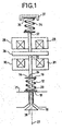
- a known device of this type is shown in Figure 1. It comprises a helical spring 12 surrounding a rod 14 secured to a valve 10 and bearing, on one side, against a stop 16 integral with the rod 14 and, on the other hand, against a stop 18 surrounding an opening 20 of the body of the corresponding cylinder 21.
- the plate 26 is installed between two electromagnets 28 and 30 traversed by the rod 22.
- These two electromagnets 28 and 30 each include a coil, conventionally shown in the cross-section of FIG. 1 by two crosses, and a magnetic circuit, respectively 29 and 31 , made of magnetic material.
- the end 32 of the rod 22 which is opposite the link 24 cooperates with the first end of another spring 34.
- This spring 34 is fixed to a support 36 integral with a frame 37.
- the springs 34 and 12 hold the plate 26 equidistant from the two electromagnets 28 and 30 when the latter do not generate a magnetic field. This position can be adjusted by varying the position of the support 36 relative to the frame 37.
- the electromagnet 28 When the electromagnet 28 is activated, it attracts the plate 26 and the latter comes into contact with a portion of the magnetic circuit of the electromagnet 28. This displacement causes a sliding of the rod 22 and the rod 14 - along an axis 27 confused with the axis of these rods - such that the head 38 of the valve 10 is brought to rest on its seat. The valve 10 is then closed.
- the electromagnet 30 When the electromagnet 30 is activated, the latter attracts the plate 26 which comes into contact with a part of the magnetic circuit of the second electromagnet, driving the rod 22 and the rod 14 along the axis 27, the head 38 moving away. hence its seat. The valve 10 is then in the open position.
- the springs 12 and 34 are associated with the movement of the rods 14 and 22 by compressing or relaxing according to the movements of the latter, a resonant electromechanical system being thus formed.
- the magnetic circuits 29 and 31 of the electromagnets are of the so-called polarized type, that is to say that they comprise a permanent magnet. This allows a magnetic locking of the plate 26 in position respectively open or closed with zero or low current in the electromagnet, respectively 30 or 28. But it is therefore necessary to provide a force during transitions from one position to another because you have to overcome the magnetic force generated by the permanent magnet. Such an effort is expensive in energy.
- the present invention results from the observation that such a control device is not energetically optimized.
- the present invention overcomes these disadvantages. It relates to an electromechanical valve control device for an internal combustion engine, characterized in that the magnetic circuit of the electromagnet and / or the plate includes a magnetic material having a remanent magnetization when the valve is in the open or closed position, said remanent magnetization being reversible so as to be canceled upon a change of position of the valve and having a coercive field included between 10 Oersted and 600 Oersted.
- Materials with remanent and reversible magnetization are also commonly referred to as semi-hard or hysteretic materials.
- the materials used in the invention have a high remanent induction as well as an intermediate coercive field in comparison to soft materials and hard materials.
- the hysteresis of a magnetic material is defined by two magnetic magnitudes: the coercive field and induction.
- the coercive field is often less than 1 Oersted (80 A / m).
- the hysteresis cycle is as wide as possible.
- the field of permanent magnets starts with materials that have a coercive field of at least 600 Oersted (5000 Ampere per meter).
- One of the disadvantages of such materials is that it is difficult to demagnetize them.
- the other magnetic quantity, the induction B characterizes the ability to possess induced magnetization. It is understood that it is advantageously as high as possible in the invention.
- a material having a high induction value as well as an intermediate coercive field can thus be remanently and reversibly magnetized.
- the magnetization of the plate and / or the magnetic circuit of the electromagnet can thus be modified. This makes it possible to have a plate and / or a magnetized magnetic circuit during holding in position of the valve. This maintenance is therefore possible with a zero or low current in the electromagnet.
- a coercive force value of 10 Oersteds makes it possible to maintain correct position in valve applications. Such a maintenance is not ensured by a simple material having a remanent magnetization of hard steels type (carbon for example) sometimes used.
- Such residual magnetism is of the type observed with a piece of steel that is momentarily magnetized and manages to attract nails, for example.
- Such a coercive field value also makes it possible to demagnetize the plate and / or the magnetic circuit of the electromagnet just before the transition from one position to another so as not to have to provide significant effort during the transition.
- the magnetization changes do not require a large amount of energy, the power consumption of the device is reduced compared to a known device.
- the material having a remanent and reversible magnetization has a coercive field included between 50 Oersted and 500 Oersted.
- Such a selective range of coercive field ensures a good maintenance and minimize the energy required to demagnetize the material.
- This material is advantageously chosen from iron-cobalt-vanadium alloys or from alnico (aluminum-nickel-cobalt) alloys with a low coercive field.
- the material having a remanent and reversible magnetization is in rolled form.
- the rolled shape is obtained when the material is produced in a strip. This is the case for FeCoVa for example.
- the rolled form reduces the induced current losses.
- the positioning of the valve in a second position is obtained by the action of a second electromagnet acting on the plate, the magnetic circuit of the second electromagnet and / or the plate including a material having a remanent and reversible magnetization.
- the plate is the element of the device including a material with remanent and reversible magnetization.
- the control device includes an electromagnet 28 and a plate 26 which is integral with a valve not shown in FIGS. 2a to 2e.
- the electromagnet 28 comprises a coil represented by two crosses on the sections shown in Figures 2a to 2e and a magnetic circuit 29 of magnetic material.
- the remanent flux Fp created by the remanent magnetization of the plate 26 in the magnetic circuit 29 of the electromagnet 28 makes it possible to maintain a significant induction in the magnetic circuit 29 of the electromagnet 28 and thus to generate an electromagnetic force between the plate 26 and the electromagnet 28. This force does not depend substantially on the intensity of the current previously applied to the coil.
- the plate 26 can then be held in position with zero or low current in the same manner as with a plate having a permanent magnetization.
- control device When the reverse current is interrupted in the coil, the control device is again in the situation shown in FIG. 2a, that is to say without pre-magnetization or with a reduced pre-magnetization and thus without any force exerted. on the board 26.
- the magnetization of the plate is effected by the flux of the coil each time the plate is attracted by the electromagnet, for example at startup or during a transition.
- the remanent magnetization of the pallet makes it possible to maintain a significant induction in the magnetic circuit. This makes it possible to obtain a holding force which may be sufficient to obtain zero or low current hold in the coil.
- a demagnetizing current is applied to demagnetize the tray.
- the advantages of the invention are notably to obtain a blocking in open or closed position with zero or low current and, at the same time, to allow inexpensive energy transitions since the magnetization can be canceled at the moment of transition.
- the cycle of application of the current to the coil defined by the intensity and the direction of the current and the durations of application, depends on the desired cycle for the opening and closing of the valve.
- the positioning of the valve in a second position is obtained by the action of a second electromagnet acting on the plate, the current intended to traverse this second electromagnet is synchronized with the current negative traversing the first electromagnet to demagnetize the plate.
- the transition is inexpensive in energy because the plate is released by the first electromagnet at the moment when it is called to move towards the second electromagnet.
- An additional advantage of the invention lies in the fact that the semi-hard materials have an apparent permeability greater than that of the magnets. This therefore generates a better efficiency of the coil.
- a device according to the invention does not present a risk of irreversible demagnetization of the plate, such a defect being all the more prejudicial in applications requiring high reliability such as an engine.
- the invention has been presented with a tray made of semi-hard material.
- the plate includes a soft magnetic material and the magnetic circuit of the electromagnet includes a magnetic material with remanent magnetization and reversible. It is also possible to envisage that the plate and the magnetic circuit of the electromagnet both include a semi-hard magnetic material.
- the positioning of the valve in a second position can also be performed according to the action of known means, including mechanical means.
- known means including mechanical means.
- only one position, open or closed, is provided according to the invention.
- the other position may for example implement a spring.
Landscapes
- Engineering & Computer Science (AREA)
- Physics & Mathematics (AREA)
- Electromagnetism (AREA)
- Power Engineering (AREA)
- Mechanical Engineering (AREA)
- General Engineering & Computer Science (AREA)
- Magnetically Actuated Valves (AREA)
- Valve Device For Special Equipments (AREA)
- Valve-Gear Or Valve Arrangements (AREA)
Claims (6)
- Vorrichtung zum Ansteuern der Öffnung und der Schließung eines Ventils (38) eines Innenverbrennungsmotors, wobei die Positionierung des Ventils (38) in zumindest einer Stellung (offen oder geschlossen) durch das Einwirken eines Elektromagneten (28) mit einer Spule und einem Magnetkreislauf (29) erreicht wird, der auf eine Scheibe (26) einwirkt, die die jeweilige Positionierung des Ventils ansteuert; sie ist dadurch gekennzeichnet, dass der Magnetkreislauf (29) des Elektromagneten (28) und/ oder die Scheibe (26) ein magnetisches Material enthalten, das eine remanente Magnetisierung aufweist, wenn das Ventil (38) offen oder geschlossen ist, wobei die remanente Magnetisierung so umkehrbar ist, dass sie bei einer Änderung der Position des Ventils (38) verschwindet, und eine Koerzitiv-Feldstärke zwischen 50 Oersted und 500 Oersted aufweist.
- Vorrichtung nach Anspruch 1, die dadurch gekennzeichnet ist, dass das Material, das eine remanente und umkehrbare Magnetisierung aufweist, unter Eisen-Kobalt-Vanadium Legierungen ausgesucht wird.
- Vorrichtung nach Anspruch 1, die dadurch gekennzeichnet ist, dass das Material, das eine remanente und umkehrbare Magnetisierung aufweist, unter Aluminium-Nickel-Kobalt Legierungen mit einer schwachen Koerzitiv-Feldstärke ausgesucht wird.
- Vorrichtung nach einem der Ansprüche 1 bis 3, die dadurch gekennzeichnet ist, dass das Material, das eine remanente und umkehrbare Magnetisierung aufweist, gewalzt ist.
- Vorrichtung nach einem der Ansprüche 1 bis 4, die dadurch gekennzeichnet ist, dass die Positionierung des Ventils in einer zweiten Stellung (geschlossen oder offen) durch das Einwirken eines zweiten Elektromagneten (30) erreicht wird, der auf die Scheibe (26) einwirkt, wobei der Magnetkreislauf (31) des zweiten Elektromagneten (30) und/ oder die Scheibe (26) ebenfalls das besagte magnetische Material enthalten.
- Innenverbrennungsmotor, der eine Steuervorrichtung nach einem der Ansprüche 1 bis 5 enthält.
Applications Claiming Priority (2)
| Application Number | Priority Date | Filing Date | Title |
|---|---|---|---|
| FR0450152A FR2865498B1 (fr) | 2004-01-27 | 2004-01-27 | Dispositif de commande a electroaimant pour une soupape de moteur a combustion interne |
| PCT/FR2005/050051 WO2005075796A1 (fr) | 2004-01-27 | 2005-01-27 | Dispositif de commande à électroaimant pour une soupape de moteur à combustion interne |
Publications (2)
| Publication Number | Publication Date |
|---|---|
| EP1774143A1 EP1774143A1 (de) | 2007-04-18 |
| EP1774143B1 true EP1774143B1 (de) | 2007-10-03 |
Family
ID=34717501
Family Applications (1)
| Application Number | Title | Priority Date | Filing Date |
|---|---|---|---|
| EP05717690A Expired - Lifetime EP1774143B1 (de) | 2004-01-27 | 2005-01-27 | Elektromagnetische steuervorrichtung für ein ventil einer brennkraftmaschine |
Country Status (7)
| Country | Link |
|---|---|
| US (1) | US7798110B2 (de) |
| EP (1) | EP1774143B1 (de) |
| AT (1) | ATE374882T1 (de) |
| DE (1) | DE602005002752T2 (de) |
| ES (1) | ES2290899T3 (de) |
| FR (1) | FR2865498B1 (de) |
| WO (1) | WO2005075796A1 (de) |
Families Citing this family (5)
| Publication number | Priority date | Publication date | Assignee | Title |
|---|---|---|---|---|
| DE202007013709U1 (de) * | 2007-10-01 | 2007-12-20 | Bürkert Werke GmbH & Co. KG | Anordnung von angereihten Magnetantrieben |
| ITGE20080036A1 (it) * | 2008-04-30 | 2009-11-01 | Dott Ing Mario Cozzani Srl | Metodo per il controllo della posizione di un attuatore elettromeccanico per valvole di compressori alternativi. |
| DE102017211332A1 (de) * | 2017-07-04 | 2019-01-10 | Siemens Aktiengesellschaft | Elektromagnetischer Auslöser für elektromagnetische Schaltgeräte |
| GB202005894D0 (en) * | 2020-04-22 | 2020-06-03 | Wastling Michael | Fast-acting toggling armature uses centring spring |
| CN115978276A (zh) * | 2022-12-28 | 2023-04-18 | 浙江工业大学 | 一种电磁阀动态特性优化方法 |
Family Cites Families (11)
| Publication number | Priority date | Publication date | Assignee | Title |
|---|---|---|---|---|
| US3422407A (en) * | 1964-10-20 | 1969-01-14 | Bell Telephone Labor Inc | Devices utilizing a cobalt-vanadium-iron magnetic material which exhibits a composite hysteresis loop |
| US3743898A (en) * | 1970-03-31 | 1973-07-03 | Oded Eddie Sturman | Latching actuators |
| JPS5175222A (de) * | 1974-12-25 | 1976-06-29 | Konan Electric Co | |
| US4533890A (en) * | 1984-12-24 | 1985-08-06 | General Motors Corporation | Permanent magnet bistable solenoid actuator |
| US5074259A (en) * | 1990-05-09 | 1991-12-24 | Pavo Pusic | Electrically operated cylinder valve |
| US5339777A (en) * | 1993-08-16 | 1994-08-23 | Caterpillar Inc. | Electrohydraulic device for actuating a control element |
| US5488340A (en) * | 1994-05-20 | 1996-01-30 | Caterpillar Inc. | Hard magnetic valve actuator adapted for a fuel injector |
| GB9613730D0 (en) * | 1996-07-01 | 1996-09-04 | Perkins Ltd | An electro-magnetically operated valve |
| JP2002043125A (ja) * | 1999-12-09 | 2002-02-08 | Sumitomo Electric Ind Ltd | 電磁アクチュエータ及びこれを用いた内燃機関用弁開閉機構 |
| FR2812024B1 (fr) * | 2000-07-18 | 2003-04-04 | Peugeot Citroen Automobiles Sa | Actionneur de soupapes de moteurs a combustion interne |
| US6685160B2 (en) * | 2001-07-30 | 2004-02-03 | Caterpillar Inc | Dual solenoid latching actuator and method of using same |
-
2004
- 2004-01-27 FR FR0450152A patent/FR2865498B1/fr not_active Expired - Fee Related
-
2005
- 2005-01-27 ES ES05717690T patent/ES2290899T3/es not_active Expired - Lifetime
- 2005-01-27 AT AT05717690T patent/ATE374882T1/de not_active IP Right Cessation
- 2005-01-27 WO PCT/FR2005/050051 patent/WO2005075796A1/fr not_active Ceased
- 2005-01-27 EP EP05717690A patent/EP1774143B1/de not_active Expired - Lifetime
- 2005-01-27 US US11/578,317 patent/US7798110B2/en active Active
- 2005-01-27 DE DE602005002752T patent/DE602005002752T2/de not_active Expired - Lifetime
Also Published As
| Publication number | Publication date |
|---|---|
| FR2865498A1 (fr) | 2005-07-29 |
| DE602005002752D1 (de) | 2007-11-15 |
| DE602005002752T2 (de) | 2008-06-12 |
| ES2290899T3 (es) | 2008-02-16 |
| WO2005075796A1 (fr) | 2005-08-18 |
| US20080035093A1 (en) | 2008-02-14 |
| ATE374882T1 (de) | 2007-10-15 |
| US7798110B2 (en) | 2010-09-21 |
| EP1774143A1 (de) | 2007-04-18 |
| FR2865498B1 (fr) | 2008-04-25 |
Similar Documents
| Publication | Publication Date | Title |
|---|---|---|
| EP1121511B1 (de) | Elektromagnetische ventilsteuerungseinrichtung und verfahren | |
| WO2000020731A1 (fr) | Actionneur electromagnetique de soupape | |
| FR2792765A1 (fr) | Actionneur lineaire electromagnetique a capteur de position | |
| WO2011073539A1 (fr) | Actionneur electromagnetique a accrochage magnetique et dispositif de coupure comportant un tel actionneur | |
| EP1174595A1 (de) | Ventilaktuator in einer Brennkraftmaschine | |
| EP1774143A1 (de) | Elektromagnetische steuervorrichtung für ein ventil einer brennkraftmaschine | |
| FR2784497A1 (fr) | Actionneur electromagnetique a palette aimantee | |
| FR2851291A1 (fr) | Actionneur electromecanique de commande de soupape pour moteur a combustion interne et moteur a combustion interne muni d'un tel actionneur | |
| EP1561914B1 (de) | Elektromagnetischer Hubventilaktuator in einer Brennkraftmaschine | |
| FR2940500A1 (fr) | Actionneur electromagnetique a double circuits de commande | |
| FR2849101A1 (fr) | Actionneur electromagnetique de soupape bibobine a aimant permanent | |
| FR2865238A1 (fr) | Actionneur electromecanique de commande de soupape pour moteur a combustion interne et moteur a combustion interne muni d'un tel actionneur | |
| EP1421590B1 (de) | Elektromagnetisches betätigungsglied mit zwei stabilen endanschlagpositionen, insbesondere zur steuerung von lufteinlasskanalventilen für verbrennungsmotoren | |
| FR2873232A1 (fr) | Dispositif de commande electromagnetique fonctionnant en basculement | |
| EP1576627B1 (de) | Elektromagnetische ventilbetätigungsvorrichtung mit einem permanentmagneten | |
| EP3939151B1 (de) | Elektromagnetische vorrichtung | |
| FR2836755A1 (fr) | Actionneur electromagnetique a force d'attraction controlee | |
| FR2784222A1 (fr) | Actionneur electromagnetique de soupape | |
| EP1561915B1 (de) | Elektromagnetischer Hubventilaktuator in einer Brennkraftmaschine | |
| EP1568858B1 (de) | Elektromagnetische Ventilsteuerungseinrichtung für Brennkraftmaschine | |
| EP0419352B1 (de) | Elektromagnetventil mit Dauermagnet | |
| EP1703089B1 (de) | Elektromagnetisch arbeitende Ventilstelleinrichtung in einem Brennkraftmaschine und Brennkraftmaschine mit einer solchen Ventilstelleinrichtung | |
| FR3003072B1 (fr) | Procede de reglage de la force magnetique d'un aimant de levee et aimant ainsi realise | |
| FR2812121A1 (fr) | Actionneur lineaire electromagnetique de soupape comportant une seule bobine | |
| EP1229560A1 (de) | Elektromagnetischer Ventil-Aktuator mit Elektromagnet für eine Brennkraftmaschine |
Legal Events
| Date | Code | Title | Description |
|---|---|---|---|
| PUAI | Public reference made under article 153(3) epc to a published international application that has entered the european phase |
Free format text: ORIGINAL CODE: 0009012 |
|
| 17P | Request for examination filed |
Effective date: 20061227 |
|
| AK | Designated contracting states |
Kind code of ref document: A1 Designated state(s): AT BE BG CH CY CZ DE DK EE ES FI FR GB GR HU IE IS IT LI LT LU MC NL PL PT RO SE SI SK TR |
|
| DAX | Request for extension of the european patent (deleted) | ||
| 17Q | First examination report despatched |
Effective date: 20070413 |
|
| RIN1 | Information on inventor provided before grant (corrected) |
Inventor name: YONNET, JEAN-PAUL Inventor name: FAGEON, CHRISTOPHE Inventor name: SEDDA, EMMANUEL |
|
| GRAP | Despatch of communication of intention to grant a patent |
Free format text: ORIGINAL CODE: EPIDOSNIGR1 |
|
| GRAS | Grant fee paid |
Free format text: ORIGINAL CODE: EPIDOSNIGR3 |
|
| GRAA | (expected) grant |
Free format text: ORIGINAL CODE: 0009210 |
|
| AK | Designated contracting states |
Kind code of ref document: B1 Designated state(s): AT BE BG CH CY CZ DE DK EE ES FI FR GB GR HU IE IS IT LI LT LU MC NL PL PT RO SE SI SK TR |
|
| REG | Reference to a national code |
Ref country code: GB Ref legal event code: FG4D Free format text: NOT ENGLISH |
|
| REG | Reference to a national code |
Ref country code: CH Ref legal event code: EP |
|
| REG | Reference to a national code |
Ref country code: IE Ref legal event code: FG4D Free format text: LANGUAGE OF EP DOCUMENT: FRENCH |
|
| REF | Corresponds to: |
Ref document number: 602005002752 Country of ref document: DE Date of ref document: 20071115 Kind code of ref document: P |
|
| GBT | Gb: translation of ep patent filed (gb section 77(6)(a)/1977) |
Effective date: 20080108 |
|
| REG | Reference to a national code |
Ref country code: ES Ref legal event code: FG2A Ref document number: 2290899 Country of ref document: ES Kind code of ref document: T3 |
|
| NLV1 | Nl: lapsed or annulled due to failure to fulfill the requirements of art. 29p and 29m of the patents act | ||
| REG | Reference to a national code |
Ref country code: GB Ref legal event code: 746 Effective date: 20080329 |
|
| PG25 | Lapsed in a contracting state [announced via postgrant information from national office to epo] |
Ref country code: NL Free format text: LAPSE BECAUSE OF FAILURE TO SUBMIT A TRANSLATION OF THE DESCRIPTION OR TO PAY THE FEE WITHIN THE PRESCRIBED TIME-LIMIT Effective date: 20071003 Ref country code: SE Free format text: LAPSE BECAUSE OF FAILURE TO SUBMIT A TRANSLATION OF THE DESCRIPTION OR TO PAY THE FEE WITHIN THE PRESCRIBED TIME-LIMIT Effective date: 20080103 |
|
| PG25 | Lapsed in a contracting state [announced via postgrant information from national office to epo] |
Ref country code: IS Free format text: LAPSE BECAUSE OF FAILURE TO SUBMIT A TRANSLATION OF THE DESCRIPTION OR TO PAY THE FEE WITHIN THE PRESCRIBED TIME-LIMIT Effective date: 20080203 Ref country code: BG Free format text: LAPSE BECAUSE OF FAILURE TO SUBMIT A TRANSLATION OF THE DESCRIPTION OR TO PAY THE FEE WITHIN THE PRESCRIBED TIME-LIMIT Effective date: 20080103 Ref country code: PL Free format text: LAPSE BECAUSE OF FAILURE TO SUBMIT A TRANSLATION OF THE DESCRIPTION OR TO PAY THE FEE WITHIN THE PRESCRIBED TIME-LIMIT Effective date: 20071003 Ref country code: LT Free format text: LAPSE BECAUSE OF FAILURE TO SUBMIT A TRANSLATION OF THE DESCRIPTION OR TO PAY THE FEE WITHIN THE PRESCRIBED TIME-LIMIT Effective date: 20071003 Ref country code: PT Free format text: LAPSE BECAUSE OF FAILURE TO SUBMIT A TRANSLATION OF THE DESCRIPTION OR TO PAY THE FEE WITHIN THE PRESCRIBED TIME-LIMIT Effective date: 20080303 |
|
| REG | Reference to a national code |
Ref country code: IE Ref legal event code: FD4D |
|
| PG25 | Lapsed in a contracting state [announced via postgrant information from national office to epo] |
Ref country code: AT Free format text: LAPSE BECAUSE OF FAILURE TO SUBMIT A TRANSLATION OF THE DESCRIPTION OR TO PAY THE FEE WITHIN THE PRESCRIBED TIME-LIMIT Effective date: 20071003 |
|
| BERE | Be: lapsed |
Owner name: PEUGEOT CITROEN AUTOMOBILES SA Effective date: 20080131 |
|
| PG25 | Lapsed in a contracting state [announced via postgrant information from national office to epo] |
Ref country code: DK Free format text: LAPSE BECAUSE OF FAILURE TO SUBMIT A TRANSLATION OF THE DESCRIPTION OR TO PAY THE FEE WITHIN THE PRESCRIBED TIME-LIMIT Effective date: 20071003 Ref country code: CZ Free format text: LAPSE BECAUSE OF FAILURE TO SUBMIT A TRANSLATION OF THE DESCRIPTION OR TO PAY THE FEE WITHIN THE PRESCRIBED TIME-LIMIT Effective date: 20071003 |
|
| PLBE | No opposition filed within time limit |
Free format text: ORIGINAL CODE: 0009261 |
|
| STAA | Information on the status of an ep patent application or granted ep patent |
Free format text: STATUS: NO OPPOSITION FILED WITHIN TIME LIMIT |
|
| PG25 | Lapsed in a contracting state [announced via postgrant information from national office to epo] |
Ref country code: MC Free format text: LAPSE BECAUSE OF NON-PAYMENT OF DUE FEES Effective date: 20080131 Ref country code: RO Free format text: LAPSE BECAUSE OF FAILURE TO SUBMIT A TRANSLATION OF THE DESCRIPTION OR TO PAY THE FEE WITHIN THE PRESCRIBED TIME-LIMIT Effective date: 20071003 Ref country code: SK Free format text: LAPSE BECAUSE OF FAILURE TO SUBMIT A TRANSLATION OF THE DESCRIPTION OR TO PAY THE FEE WITHIN THE PRESCRIBED TIME-LIMIT Effective date: 20071003 |
|
| 26N | No opposition filed |
Effective date: 20080704 |
|
| PG25 | Lapsed in a contracting state [announced via postgrant information from national office to epo] |
Ref country code: IE Free format text: LAPSE BECAUSE OF FAILURE TO SUBMIT A TRANSLATION OF THE DESCRIPTION OR TO PAY THE FEE WITHIN THE PRESCRIBED TIME-LIMIT Effective date: 20071003 |
|
| PG25 | Lapsed in a contracting state [announced via postgrant information from national office to epo] |
Ref country code: EE Free format text: LAPSE BECAUSE OF FAILURE TO SUBMIT A TRANSLATION OF THE DESCRIPTION OR TO PAY THE FEE WITHIN THE PRESCRIBED TIME-LIMIT Effective date: 20071003 Ref country code: GR Free format text: LAPSE BECAUSE OF FAILURE TO SUBMIT A TRANSLATION OF THE DESCRIPTION OR TO PAY THE FEE WITHIN THE PRESCRIBED TIME-LIMIT Effective date: 20080104 |
|
| PG25 | Lapsed in a contracting state [announced via postgrant information from national office to epo] |
Ref country code: BE Free format text: LAPSE BECAUSE OF NON-PAYMENT OF DUE FEES Effective date: 20080131 |
|
| PG25 | Lapsed in a contracting state [announced via postgrant information from national office to epo] |
Ref country code: SI Free format text: LAPSE BECAUSE OF FAILURE TO SUBMIT A TRANSLATION OF THE DESCRIPTION OR TO PAY THE FEE WITHIN THE PRESCRIBED TIME-LIMIT Effective date: 20071003 |
|
| PG25 | Lapsed in a contracting state [announced via postgrant information from national office to epo] |
Ref country code: CY Free format text: LAPSE BECAUSE OF FAILURE TO SUBMIT A TRANSLATION OF THE DESCRIPTION OR TO PAY THE FEE WITHIN THE PRESCRIBED TIME-LIMIT Effective date: 20071003 |
|
| REG | Reference to a national code |
Ref country code: CH Ref legal event code: PL |
|
| PG25 | Lapsed in a contracting state [announced via postgrant information from national office to epo] |
Ref country code: CH Free format text: LAPSE BECAUSE OF NON-PAYMENT OF DUE FEES Effective date: 20090131 Ref country code: LI Free format text: LAPSE BECAUSE OF NON-PAYMENT OF DUE FEES Effective date: 20090131 |
|
| PG25 | Lapsed in a contracting state [announced via postgrant information from national office to epo] |
Ref country code: FI Free format text: LAPSE BECAUSE OF FAILURE TO SUBMIT A TRANSLATION OF THE DESCRIPTION OR TO PAY THE FEE WITHIN THE PRESCRIBED TIME-LIMIT Effective date: 20071003 |
|
| PG25 | Lapsed in a contracting state [announced via postgrant information from national office to epo] |
Ref country code: LU Free format text: LAPSE BECAUSE OF NON-PAYMENT OF DUE FEES Effective date: 20080127 Ref country code: HU Free format text: LAPSE BECAUSE OF FAILURE TO SUBMIT A TRANSLATION OF THE DESCRIPTION OR TO PAY THE FEE WITHIN THE PRESCRIBED TIME-LIMIT Effective date: 20080404 |
|
| PG25 | Lapsed in a contracting state [announced via postgrant information from national office to epo] |
Ref country code: TR Free format text: LAPSE BECAUSE OF FAILURE TO SUBMIT A TRANSLATION OF THE DESCRIPTION OR TO PAY THE FEE WITHIN THE PRESCRIBED TIME-LIMIT Effective date: 20071003 |
|
| PG25 | Lapsed in a contracting state [announced via postgrant information from national office to epo] |
Ref country code: IT Free format text: LAPSE BECAUSE OF NON-PAYMENT OF DUE FEES Effective date: 20080131 |
|
| REG | Reference to a national code |
Ref country code: ES Ref legal event code: GC2A Effective date: 20130213 |
|
| REG | Reference to a national code |
Ref country code: FR Ref legal event code: PLFP Year of fee payment: 12 |
|
| REG | Reference to a national code |
Ref country code: FR Ref legal event code: PLFP Year of fee payment: 13 |
|
| REG | Reference to a national code |
Ref country code: FR Ref legal event code: PLFP Year of fee payment: 14 |
|
| REG | Reference to a national code |
Ref country code: FR Ref legal event code: CA Effective date: 20180312 Ref country code: FR Ref legal event code: CD Owner name: PEUGEOT CITROEN AUTOMOBILES SA, FR Effective date: 20180312 |
|
| PGFP | Annual fee paid to national office [announced via postgrant information from national office to epo] |
Ref country code: ES Payment date: 20190201 Year of fee payment: 15 |
|
| REG | Reference to a national code |
Ref country code: DE Ref legal event code: R079 Ref document number: 602005002752 Country of ref document: DE Free format text: PREVIOUS MAIN CLASS: F01L0009040000 Ipc: F01L0009200000 |
|
| PGFP | Annual fee paid to national office [announced via postgrant information from national office to epo] |
Ref country code: GB Payment date: 20201218 Year of fee payment: 17 |
|
| REG | Reference to a national code |
Ref country code: ES Ref legal event code: FD2A Effective date: 20210604 |
|
| PG25 | Lapsed in a contracting state [announced via postgrant information from national office to epo] |
Ref country code: ES Free format text: LAPSE BECAUSE OF NON-PAYMENT OF DUE FEES Effective date: 20200128 |
|
| PGFP | Annual fee paid to national office [announced via postgrant information from national office to epo] |
Ref country code: FR Payment date: 20211215 Year of fee payment: 18 |
|
| PGFP | Annual fee paid to national office [announced via postgrant information from national office to epo] |
Ref country code: DE Payment date: 20211215 Year of fee payment: 18 |
|
| GBPC | Gb: european patent ceased through non-payment of renewal fee |
Effective date: 20220127 |
|
| PG25 | Lapsed in a contracting state [announced via postgrant information from national office to epo] |
Ref country code: GB Free format text: LAPSE BECAUSE OF NON-PAYMENT OF DUE FEES Effective date: 20220127 |
|
| REG | Reference to a national code |
Ref country code: DE Ref legal event code: R119 Ref document number: 602005002752 Country of ref document: DE |
|
| PG25 | Lapsed in a contracting state [announced via postgrant information from national office to epo] |
Ref country code: DE Free format text: LAPSE BECAUSE OF NON-PAYMENT OF DUE FEES Effective date: 20230801 |
|
| PG25 | Lapsed in a contracting state [announced via postgrant information from national office to epo] |
Ref country code: FR Free format text: LAPSE BECAUSE OF NON-PAYMENT OF DUE FEES Effective date: 20230131 |