EP1774672B1 - Appareil de transmission et systeme de communication utilisant cet appareil - Google Patents
Appareil de transmission et systeme de communication utilisant cet appareil Download PDFInfo
- Publication number
- EP1774672B1 EP1774672B1 EP05767337A EP05767337A EP1774672B1 EP 1774672 B1 EP1774672 B1 EP 1774672B1 EP 05767337 A EP05767337 A EP 05767337A EP 05767337 A EP05767337 A EP 05767337A EP 1774672 B1 EP1774672 B1 EP 1774672B1
- Authority
- EP
- European Patent Office
- Prior art keywords
- characteristic value
- information
- transmission signal
- adapter
- transmission apparatus
- Prior art date
- Legal status (The legal status is an assumption and is not a legal conclusion. Google has not performed a legal analysis and makes no representation as to the accuracy of the status listed.)
- Expired - Lifetime
Links
Images







Classifications
-
- H—ELECTRICITY
- H04—ELECTRIC COMMUNICATION TECHNIQUE
- H04B—TRANSMISSION
- H04B3/00—Line transmission systems
- H04B3/54—Systems for transmission via power distribution lines
-
- H—ELECTRICITY
- H04—ELECTRIC COMMUNICATION TECHNIQUE
- H04B—TRANSMISSION
- H04B2203/00—Indexing scheme relating to line transmission systems
- H04B2203/54—Aspects of powerline communications not already covered by H04B3/54 and its subgroups
- H04B2203/5404—Methods of transmitting or receiving signals via power distribution lines
- H04B2203/5408—Methods of transmitting or receiving signals via power distribution lines using protocols
-
- H—ELECTRICITY
- H04—ELECTRIC COMMUNICATION TECHNIQUE
- H04B—TRANSMISSION
- H04B2203/00—Indexing scheme relating to line transmission systems
- H04B2203/54—Aspects of powerline communications not already covered by H04B3/54 and its subgroups
- H04B2203/5404—Methods of transmitting or receiving signals via power distribution lines
- H04B2203/5416—Methods of transmitting or receiving signals via power distribution lines by adding signals to the wave form of the power source
-
- H—ELECTRICITY
- H04—ELECTRIC COMMUNICATION TECHNIQUE
- H04B—TRANSMISSION
- H04B2203/00—Indexing scheme relating to line transmission systems
- H04B2203/54—Aspects of powerline communications not already covered by H04B3/54 and its subgroups
- H04B2203/5429—Applications for powerline communications
- H04B2203/5445—Local network
-
- H—ELECTRICITY
- H04—ELECTRIC COMMUNICATION TECHNIQUE
- H04B—TRANSMISSION
- H04B2203/00—Indexing scheme relating to line transmission systems
- H04B2203/54—Aspects of powerline communications not already covered by H04B3/54 and its subgroups
- H04B2203/5462—Systems for power line communications
- H04B2203/5483—Systems for power line communications using coupling circuits
-
- H—ELECTRICITY
- H04—ELECTRIC COMMUNICATION TECHNIQUE
- H04B—TRANSMISSION
- H04B2203/00—Indexing scheme relating to line transmission systems
- H04B2203/54—Aspects of powerline communications not already covered by H04B3/54 and its subgroups
- H04B2203/5462—Systems for power line communications
- H04B2203/5491—Systems for power line communications using filtering and bypassing
Definitions
- the present invention relates to a transmission apparatus for outputting input data as a transmission signal. More specifically, the present invention is directed to a transmission apparatus and a communication system using the transmission apparatus, in which even when a characteristic value is changed which should be set as to a transmission signal, the transmission apparatus and the communication system are capable of being properly adapted to the change of the characteristic value to be set in a flexible manner without altering a circuit arrangement of the transmission apparatus.
- characteristic values which should be set are not always constant, there are some cases that these characteristic values are changed due to alterations of restricted contents made in connect ion with alterations of laws, and/or due to changes in use areas of transmission apparatus.
- a band rejection filter must be newly added to a transmission apparatus. That is, since there are some cases that circuit arrangements of transmission apparatus must be changed, there is such a problem that these transmission apparatus cannot be properly adapted to the changed restricted contents in a flexible manner.
- PLC power line communications
- a problem to be solved is given as follows: That is, in the case that a characteristic value is changed which should be set as to a transmission signal, since a circuit arrangement of a transmission apparatus must be changed, the transmission apparatus cannot be properly adapted to the change in the characteristic value to be set in a flexible manner.
- a power-line carrier communication apparatus which comprises a transmission unit, a reception unit, a control unit and a power-line coupling circuit.
- the transmission unit includes a signal point mapping device for mapping a plurality of bit streams produced from transmission data, a wavelet inverse transforming device for modulating a respective sub-carriers by wavelet waveforms and a D/A converter for converting the waveform series data into an analog temporal waveform series signal.
- the reception unit comprises an A/D converter for obtaining waveform data from a power-line communication signal, a wavelet transforming device for wavelet-transforming a sampling-series waveform data into signal point data of the respective sub-carriers.
- the reception unit further includes a symbol judging device for judging bit streams mapped by the signal point mapping device by inverse-mapping a plurality of these signal point data, and for synthesizing the judged bit streams with each other as a reception data series.
- substation control technology is regarded which is related to a system for configuration of appliances and networks.
- a situation is regarded having at least one appliance to be configured and having elements which are configured to a specific manner.
- the configuration system comprises configuration means for reconfiguration of the appliance on the basis of received new configuration information.
- a configuration server is connected via a network to the at least one appliance to be configured and the configuration server has composition means for creation of new configuration information for the appliance to be configured and means for determination of the present configuration of the at least one appliance to be configured.
- EP 1 398 885 a communication optimization method is described for multi-user OFDM digital transmission systems using the electrical network.
- the receivers of the equipment monitor the quality of the communication and estimate the signal/noise ratio (S/N) of the uplink and downlink channel carriers.
- the user pieces of equipment perform said surveillance independently of whether or not said equipment is the recipient of the transmission.
- the optimum transmission mode is selected using said surveillance.
- the network can be divided up optimally in terms of frequency and time and the transmission capacity of the multiple pieces of user equipment can be maximized.
- the invention is suitable for point-to-multipoint bi-directional communication across the electrical network.
- US 6,456,192 a system and method is described for detecting power line null frequencies and for adjusting the transmit frequency and transmit powered maximized the reliability and efficiency of the AC power line transmission link.
- the invention uses a programmable logic device in the transmitter which transmits multiple frequencies to a receiver.
- a receiver detects and records the bit error rate and/or the received noise per frequency and communicates this information to the transmitter.
- the optimal frequency is identified or selected. Generally, the optimal frequency is the frequency requiring the lowest transmit power while maintaining an acceptable bit error rate or an acceptable noise level.
- a major feature of the present invention is given as follows: That is, in a transmission apparatus of the present invention, a characteristic value retriever retrieves characteristic value information indicative of another characteristic value, which should be newly set as to a transmission signal; and a characteristic value modificator controls a characteristic value determinator in such a manner that a characteristic value which has been set is changed into another characteristic value which is indicated by the retrieved characteristic value information so as to set the changed characteristic value.
- the transmission apparatus of the present invention since the characteristic value information of the characteristic value is retrieved which should be newly set as to the transmission signal, the characteristic value of the transmission signal which has been set is changed into the characteristic value which should be newly set so as to set the changed characteristic value. As a result, even in such a case that such a characteristic value which should be set is changed, the transmission apparatus can easily change the characteristic value of the transmission signal without changing the circuit arrangement of the transmission apparatus. As a consequence, for example, even in such a case that the a content of a restriction is changed in connection with an alteration of a law, and/or the use area of the transmission apparatus is changed, the transmission apparatus can be properly adapted in the flexible manner to the change in the characteristic value which should be set.
- the characteristic value information of the characteristic value which should be newly set as to the transmission signal is retrieved, the characteristic value of the transmission signal which has been set is changed into the characteristic value which should be newly set and this changed characteristic value is set.
- the characteristic value of the transmission signal can be easily changed without changing the circuit arrangement of the transmission apparatus.
- the transmission apparatus can be properly adapted to this change in a flexible manner.
- the characteristic value determinator (8) sets a frequency band of the transmission signal (SS) to (for example, ⁇ f1);
- the transmitting signal generator (5) is comprised of:
- the transmitting signal generator (5) is further comprised of:
- the characteristic value determinator (8) sets a power level of the transmission signal (SS);
- the transmission signal generator (5) is further comprised of:
- the transmitting signal generator (5) outputs the generated transmission signal (SS) via a power line (for example, 2) .
- the communication apparatus can be properly adapted to these restricted contents in the flexible manner.
- the communication apparatus uses such frequency bands which are utilized in the presently existing communication systems such as, for example, amateur radio communications and shortwave broadcasting systems, the interference with respect to these presently existing communication systems can be firmly prevented.
- the transmission apparatus (1) is further comprised of:
- the user of the transmission apparatus no longer checks the characteristic values which should be set as to the respective areas, and thus, the cumbersome operation by the user can be reduced.
- the transmission apparatus (1) is further comprised of:
- the user of the transmission apparatus manipulates the signal input unit, the user can designate the area of the characteristic value information which is retrieved from the characteristic value information table.
- the degree of freedom may be set to the changing/setting operation of the characteristic value, and the transmission apparatus can be properly adapted to the request of the user in the flexible manner.
- the transmission apparatus (1) is further comprised of:
- the characteristic value of the transmission signal is changed to beset.
- the characteristic value can be automatically changed to be set without giving the cumbersome operation to the user of the transmission apparatus.
- the server stores the frequency band table and transmits the frequency band data corresponding to the use area of the communication apparatus to the communication apparatus, so that the frequency bands as to the respective areas can be managed on the side of the server.
- the present frequency band can be changed so as to set a proper frequency band.
- the transmission apparatus (1) is freely connected via a gateway (22) to the network (21);
- the server (30) is comprised of:
- the transmission value of the transmission signal is changed to be set by using the area information set in the gateway.
- the area information indicative of the use area of the transmission apparatus need not be monitored with respect to the transmission apparatus, and thus, the degree of freedom for the monitoring subject can be widened.
- Fig. 1 is an explanatory diagram for schematically showing a home-use network 600 with employment of a communication apparatus 1.
- the home-use network 600 corresponds to a LAN (Local Area Network) constructed in a home. It should be noted that the LAN need not be always constructed inside a home, but may be arranged inside an office, and a facility (hospital, school etc.).
- the home-use network 600 contains a power line 2 of a commercial power supply.
- Various sorts of domestic electric appliances have been connected via a communication apparatus 1 to the power line 2.
- a television 3A, a personal computer (will be referred to as a "PC" hereinafter) 3B, an illumination 3C, and the like have been connected to the power line 2 as the domestic electric appliances 3.
- PC personal computer
- Fig. 2 is a perceptive view for showing an outer appearance of a front surface of the communication apparatus 1.
- Fig. 3 is a perspective view for representing an outer appearance of a rear surface of the communication apparatus 1.
- the communication apparatus 1 according to an embodiment mode of the present invention corresponds to a modem as indicated in Fig. 2 and Fig. 3 .
- the communication apparatus 1 has contained a housing 101.
- a light emitting unit 105 constituted by an LED (Light Emitting Diode), a display unit 106 arranged by a liquid crystal display (LCD) , or an organic EL (Electro-Luminescence), and a switch 11 have been provided on a front surface of the housing 101.
- a power supply connector 102 As represented in Fig. 3 , a power supply connector 102, a LAN-purpose modular jack 103 such as RJ45, and a D-sub connector 104 have been provided on a rear surface of the housing 101. As indicated in Fig. 3 , a parallel cable 108 is connected to the power supply connector 102. A LAN cable 109 is connected to the modular jack 103. AD-sub cable (notshown) is connected to the Dsub connector 104.
- this communication apparatus 1 may be alternatively realized by a mobile communication terminal, for example, a portable telephone and a PDA (Personal Digital Assistant) if a communication function is équipped with such a mobile communication terminal, namely this communication apparatus 1 need not be always realized by the modem.
- the communication apparatus 1 may be realized by an electric appliance containing a modem, while this electric appliance corresponds to such a domestic electric appliance as a DVD recorder, and a set-top box.
- the communication apparatus 1 corresponds to such a modem which performs a communication by using the power line 2 as a transfer path (namely, power line communication, PLC: Power Line Communication).
- PLC Power Line Communication
- this modem will be referred to as a "PLC adaptor" hereinafter.
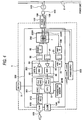
- Fig. 4 is a block diagram for indicating one example of hardware of the PLC adaptor 1.
- the PLC adaptor 1 has contained a circuit module 200, a switching power supply 300, and the switch 11.
- the switching power supply 300 applies various sorts of voltage (for instance, +1.2 V, +3.3 V, and +12 V) to the circuit module 200.
- a main IC 201 In this circuit module 200, a main IC 201, an AFE IC (Analog Front End ⁇ IC) 202, a bandpass filter 55, a driver IC 15, a coupler 206, another bandpass filter 61, an AMP (Amplifier) IC 208, another bandpass filter 21, an ADC (A/D converter) ⁇ IC 22, a transmitter memory 10, and an Ethernet PHY ⁇ IC 212 have been provided.
- the power supply connector 102 is connected via a plug 400 and a plug socket 500 to the power line 2.
- the main IC 201 has been constituted by a CPU (Central Processing Unit) 9, a PLC ⁇ MAC (Power Line Communication ⁇ Media Access Control layer) block 201C, and a PLC ⁇ PHY (Power Line Communication ⁇ Physical layer) block 201B.
- the CPU 9 has mounted thereon a 32-bit RISC (Reduced Instruction Set Computer) processor.
- the PLC ⁇ MAC block 201C manages MAC layers as to a transmission signal and a reception signal whereas the PLC ⁇ PHY block 210B manages PHY layers as to a transmission signal and a reception signal.
- the AFE ⁇ IC 202 has been constituted by a D/A converter (DAC) 53, an A/D converter (ADC) 63, and amplifiers 54 and 62.
- the coupler 206 has been arranged by a coil transformer 7, and coupling-purpose capacitors 206A and 206B.
- the transmitter memory 10 may be constituted by such a memory as a ROM (Read-Only Memory) and a RAM (Random Access Memory).
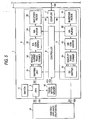
- Fig. 1 is a functional block diagram for indicating an example of the PLC adaptor (namely, communication apparatus) 1.
- the PLC adaptor 1 has been connected via the parallel cable 108 to the power line 2, and has been connected via the LAN cable 109 to the television 3A.
- the PLC adaptor 1 relays the power line 2 to the television 3A.
- the power line 2 corresponds to such a parallel cable which transfers thereto a voltage (for example, AC 100 V) of a commercial power supply.
- the power line 2 which is employed in the power line communication need not be always a power line of a commercial power supply, but may be realized by a power line of a DC power supply by which AC 100 V has been converted into a DC voltage.
- the PLC adaptor 1 has contained a transmitter 5, a receiver 6, a coupler 7, a controller 8, a CPU 9, a transmitter memory 10, and the switch 11.
- the transmitter 5 has contained a mapping unit 51 including a serial-to-parallel converter, a wavelet inverse transmitter 52, a D/A converter 53, an amplifier 54, and a bandpass filter 55.
- the receiver 6 has contained a bandpass filter 61, a gain amplifier 62, an A/D converter 63, a wavelet transformer 64, and a demapper 65.
- the mapping unit 51, the wavelet inverse transformer 52, the wavelet transformer 64, and the demapper 65, the PLC PHY block 201B of the main IC 201 shown in Fig. 4 may function.
- the transmitter 5 may function as one example of a transmitting signal generator.
- the controller 8 may function as one example of a characteristic value determinator.
- the CPU 9 may function as one example of a characteristic value retriever, a characteristic value modifier, and an area information checker.
- the mapping unit 51 may function as one example of a sub-carrier selector, a bit-data generator, and a symbol mapping unit.
- a frequency band table FDT shown in Fig. 6 has been previously stored in the transmitter memory 10 of the PLC adaptor 1.
- Fig. 6 is a schematic diagram for indicating an example of a content of the frequency band table FDT.
- the frequency band table FDT has stored thereinto frequency band data FD which correspond to areas "AR" respectively.
- the frequency band data FD1, FD2, FD3, --- show frequency bands ⁇ f1, ⁇ f2, ⁇ f3, ---, respectively, and these frequency band data ⁇ f1, ⁇ f2, ⁇ f3, ---, correspond to areas AR1, AR2, AR3, ---, respectively.
- the areas "AR” indicate, for example, "countries.”
- the frequency band table FDT represents frequency bands which can be used in power line communications in accordance with legal restrictions of the respective countries. It shouldbe understood that the areas "AR” need not always correspond to "countries", but may correspond to, for example, "states” in USA if usable frequency bands correspond to different regions.
- use area data "ARD” have been stored in the transmitter memory 10, while these use area data “ARD” show areas where the PLC adaptor 1 is used (will be simply referred to as “use areas” hereinafter).
- use areas show areas where the PLC adaptor 1 is used (will be simply referred to as “use areas” hereinafter).
- the PLC adaptor 1 is under use in, for example, the area "AR1”
- the use area data "ARD” indicative of the area "AR1” has been stored as default.
- the controller 8 When the communication operation is commenced (for instance, when the PLC adaptor 1 is initiated), the controller 8 reads out the use area data "ARD" which has been stored in the transmitter memory 10, and then, retrieves the frequency band data "FD” which corresponds to the area "AR1” indicated by this read use area data "ARD” from the transmitter memory 10. As indicated in Fig. 6 , since the frequency band data FD corresponding to the area "AR1" corresponds to "FD1", the controller 8 retrieves the frequency band data FD1 from the transmitter memory 10 as indicated in Fig. 5 . AS shown in Fig.
- the controller 8 instructs the mapping unit 51 of the transmitter 5 in such a manner that a sub-carrier "SC” corresponding to the frequency band “ ⁇ f1” is selected from a plurality of sub-carriers "SC” (will be explained later).
- the frequency band " ⁇ f” may be set to " ⁇ f1.”
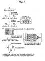
- Fig. 7 is an explanatory diagram for explaining an example of transmission operation, namely a diagram for indicating flows of transmission data "SD.”
- Fig. 8 is an explanatory diagram for showing one example of the transmission operation, namely Fig. 8 is a block diagram for indicating an example of the wavelet inverse transformer 52.
- Fig. 9 is an explanatory diagram for indicating an example of the transmission operation, namely a diagram for indicating an example of the sub-carrier "SC.”
- the television 3A outputs the transmission data "SD" to the PLC adaptor 1.
- the transmission data SD is indicated by, for example, "0001111010110100.”
- this transmission data SD is entered via the CPU 9 of the PLC adaptor 1 to the mapping unit 51 of the transmitter 5.
- the mapping unit 51 produces a plurality of bit streams BL having proper lengths from the inputted transmission data SD. For example, the mapping unit 51 divides the transmission data SD "0001111010110100” into “00”, “01”, “11”, “10”, “10”, “11”, “01”, and “00”, namely every 2 bits, as indicated in the upper portion of Fig. 7 , so as to produce the plural bit streams BL. Then, the mapping unit 51 maps the produced bit streams BL to symbols of PAM (Pulse Amplitude Modulation) respectively so as to produce symbol data "PD.”
- PAM Pulse Amplitude Modulation
- the mapping unit 51 maps the produced bit streams BL of "00”, “01”, “11”, “10”, “11”, “01”, and “00” to such symbols of "+1", “+3", "-3", “-1", "-1", “-3”, “+3", and "+1” so as to produce symbol data "PD.”
- the mapping unit 51 inputs the produced symbol data "PD" into the wavelet inverse transformer 52.
- this digital modulation is not especially limited only to the PAM (Pulse Amplitude Modulation), but may be alliteratively realized by, for example, the BPSK (Binary Phase Shift Keying), the QPSK (Quadrature Phase Shift Keying), and the QAM (Quadrature Amplitude Modulation) methods.
- PAM Pulse Amplitude Modulation
- BPSK Binary Phase Shift Keying
- QPSK Quadrature Phase Shift Keying
- QAM Quadrature Amplitude Modulation
- the wavelet inverse transformer 52 is arranged by an input unit 52A and an inverse transforming unit 52B.
- the input unit 52A is constituted by a plurality of input units 52A1, 52A2, ---, whose total number is equal to a total number of the sub-carriers "SC.” It should also be noted that a total number of the sub-carriers SC may be freely set within a range of power of 2 in the wavelet transforming stage. However, in this embodiment mode 1, for the sake of simple explanation, while such a wavelet transform for dividing the frequency band " ⁇ f" by 4 is used, as shown in Fig.
- the total number of these sub-carriers SC is selected to be 4 sub-carriers of "SC1", “SC2”, “SC3”, and “SC4.” That is to say, as indicated in Fig. 8 , the input unit 52A of the wavelet inverse transformer 52 has been constituted by 4 sets of input units 52A1, 52A2, 52A3, and 52A4, which correspond to the sub-carriers of SC1, SC2, SC3, and SC4, respectively.
- a filter length may be equal to such a value obtained by multiplying the total number of the sub-carriers SC by an integer, and may be freely set within a range similar to that for the total number of the sub-carriers SC.
- the wavelet transforming operation is carried out by employing two symbol data PD.
- the produced symbol data PD are inputted to these four input units 52A1, 52A3, 52A3, and 52A4.
- a table "T1" of Fig. 7 it is so assumed that "+1", “+3", “-3”, and "-1" corresponding to a front stage (namely, left portion of Fig. 7 ) of the symbol data PD are allocated to the sub-carriers of SC1, SC2, SC3, and SC4, and furthermore, "-1", "-3", ""+3"., and "+1" corresponding to a rear stage (namely, right portion of Fig. 7 ) of this symbol data PD are allocated thereto.
- Fig. 7 As indicated in Fig.
- the mapping unit 51 inputs the symbol data of "+1" and "-1” into the input unit 52A1; inputs the symbol data of "+3” and “-3” into the input unit 52A2; inputs the symbol data of "-3” and “+3” into the input unit 52A3; and inputs the symbol data of "-1” and "+1” into the input unit 52A4.
- the respective symbol data PD may be mapped to the sub-carriers of SC1, SC2, SC3, and SC4.
- the input unit 52A outputs the entered respective symbol data PD to the inverse transforming unit 52B.
- the inverse transforming unit 52B performs the wavelet inverse transforming operation with respect to the respective symbol data PD which have been mapped to the sub-carriers SC1, SC2, SC3, and SC4 so as to produce temporal sampling values of the transmission waveform on the time axis within 1 symbol time period; and then, outputs temporal waveform series data TD "0.7034", "0.6356", "0.9474", "2.5523",
- the D/A converter 53 D/A-converts these temporal waveform series data TD into analog temporal waveform series signals, and then, outputs these analog signals in a constant sampling time,
- the amplifier 54 amplifies the outputted transmission waveforms up to transmission signal levels, and the bandpass filter 55 eliminates an unnecessary frequency component therefrom, and thus, outputs the filtered signal as a transmission signal "SS" as represented in Fig. 5 .
- the coupler 7 outputs the transmission signal SS to the power line 2, the waveform of which has been shaped by the bandpass filter 55.
- the coupler 7 receives the transmission signal SS from the power line 2 as a reception signal RS, and then, outputs this reception signal RS to the receiver 6 as shown in Fig. 5 .
- the bandpass filter 61 of the receiver 6 eliminates noise signals outside the relevant band from the inputted reception signal RS.
- this amplifier 62 adjusts the signal level of the reception signal RS based upon this set converting gain in such a manner that the adjusted signal level may be stored in the dynamic range of the A/D converter 63.
- the A/D converter 63 samples the signal waveform of the reception signal RS whose signal level has been adjusted at the same timing as the sampling timing of the transmitter side so as to produce a digital signal of this reception signal RS.
- the wavelet transformer 64 performs the wavelet transforming'operation with respect to the digital waveform data of the reception signal RS so as to obtain symbol data PD of the sub-carriers SC1, SC2, SC3, and SC4.
- the demapper 65 demaps these symbol data PD, and restores the demapped symbol data PD into the mostapproximate bit stream BL so as to obtain reception data "RD.” Then, as shown in Fig. 1 , the demapper 65 outputs this reception data RD to the electric appliance 3, and thus, the reception operation is carried out by the PLC adaptor 1. It should also be noted that the PLC adaptor 1 need not always perform the reception operation, but may simply function as a transmitter.
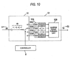
- Fig. 10 is an explanatory diagram for explaining an example of control operation for selecting a sub-carrier SC.
- Fig. 11 is a diagram-for graphically representing an example of a frequency spectrum in the case that the frequencyband " ⁇ f" is changed and the changed frequency band " ⁇ f" is set.
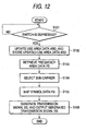
- Fig. 12 is a flow chart for describing an example of communication operations executed by the PLC adaptor 1.
- the PLC adaptor 1 is moved from the area AR1 to the area AR2 (for example, from Japan to USA), and the home-use network 600 operable by way of the power line communication shown in Fig. 1 is again arranged in this area AR2.
- the switch 11 has been provided in this PLC adaptor 1, since the user of the PLC adaptor 1 depresses this switch 11 (step S101 of Fig. 12 ), the use area of the PLC adaptor 1 may be designated.
- the CPU 9 updates the use area data ARD stored in the transmitter memory 10 from the area AR1 into the area AR2 indicated by the entered signal, and then, stores this updated use area data ARD into the transmitter memory 10 (step S102 of Fig. 12 ).
- the switch 11 corresponds to a manually operable mechanical switch, for example, a membrane switch (seat switch) and the like may be alternatively applied to this switch 11.
- this switch 11 neednot always be constructed of such amembrane switch.
- various sorts of switches may be applied to this switch 11, for example, a dip switch may be alternatively employed. Since the changing/setting process operation of the frequency band is normally carried out only during the initial setting operation, it is preferable to employ such a dip switch as this switch 11, which is made compact and is not manipulated in a careless manner. Also, if an erroneous'manipulation preventing cover is provided on this switch 11, then a similar effect may be achieved.
- the controller 8 When the use area data ARD is updated as the area data AR2 and this area data AR2 is stored, the controller 8 reads out the use area data ARD stored in the transmitter memory 10, and then, retrieves such a frequency data FD from the transmitter memory 10, which corresponds to the area AR2 indicated by this read use area data ARD (step S103 of Fig. 12 ). As indicated in Fig. 6 , since the frequency data FD corresponding to the area AR2 corresponds to FD2, the controller 8 retrieves frequency band data FD2 from the transmitter memory 10 as indicated in Fig. 5 .
- the controller 8 issues such an instruction to the mapping unit 51 of the transmitter 5 in such a manner that the mapping unit 51 selects such a sub-carrier SC corresponding to this frequency band ⁇ f2 from the four sub-carriers of SC1, SC2, SC3, and SC4 (step S104 of Fig. 12 ).
- the sub-carriers corresponding to the frequency band ⁇ f2 are "SC2" and "SC3.” That is to say, these sub-carriers of SC3 and SC3 are selected.
- the mapping unit 51 may input the symbol data PD of "+1", “-3", ---, into the input unit 52A2, and also, may input the symbol data PD of "+3", "-1", ---, into the input unit 52A3. In other words, the mapping unit 51 maps the symbol data PD only to the selected sub-carriers of SC2 and SC3.
- the inverse transforming unit 52B performs a wavelet inverse transforming operation with respect to the respective symbol data PD which have been mapped only to the sub-carriers SC2 and SC3, and the transmitter 5 outputs the transmission signal SS to which a similar process operation to the above-explained process operation has been carried out to the power line 2 (step S106 of Fig. 12 ).
- the sub-carriers SC2 and SC3 corresponding to the frequency band " ⁇ f2" are selected as the sub-carrier SC, the frequency band " ⁇ f" of the outputted transmission signal SS has been changed from “ ⁇ f1" to " ⁇ f2" and the changed frequency band " ⁇ f2" has been set.
- the frequency spectrum of the transmission signal SS is controlled within such a range of a frequency spectrum which may be used in the area AR2.
- a frequency spectrum "SP AR " (indicated by broken line) which can be used in the area AR2 owns restricted regions "LA1" and “LA2” in the frequency of, for example, 0.02 to 0.35 Krad/s
- the output power is controlled within the range of the above-described frequency spectrum "SP AR " in a frequency spectrum "SP ss " (indicated by solid line) of the transmission signal SS .
- both the sub-carriers SC2 and SC3 are not made coincident with the frequency spectrum "SP SS " shown in Fig. 11 .
- the changing/setting process operation of the frequency band " ⁇ f" is carried out in a similar manner to the above-explained manner, so that the frequency spectrum "SP SS " of the transmission signal SS may be controlled with such a range of the frequency spectrum "SP AR " which can be used in the respective areas "AR.”
- the frequency band " ⁇ f" of the transmission signal SS which has been set is changed to such a frequency band " ⁇ f” which should be newly set, and this changed frequency band “ ⁇ f” is set.
- the frequency band " ⁇ f" of the transmission signal SS may be readily changed without additionally providing a band injection filter, namely while the circuit arrangement of the communication apparatus is not changed.
- the communication apparatus can be properly adapted to the change of the frequency band ⁇ f which should be set in the flexible manner.
- the communication apparatus can be properly adapted to the change in the frequency band ⁇ f which should be set in the flexible manner without additionally employing the band rejection filter, even when the communication apparatus is arranged in such a manner that this communication apparatus can be used in a plurality of areas AR, such band rejection filters whose filter coefficients are different from each other with respect to each of the areas "AR" (for example, every country) are no longer prepared. As a result, it is possible to avoid that the circuit scale as to the communication apparatus is increased. Also, in the case that the communication apparatus is operated in a high speed, it can avoid that power consumption is increased because the band rejection filter is additionally provided.
- the communication apparatus can be properly adapted to these restricted contents in the flexible manner.
- the communication apparatus uses such frequency bands which are utilized in the presently existing communication systems such as, for example, amateur radio communications and shortwave broadcasting systems, the interference with respect to these presently existing communication systems can be firmly prevented.
- the frequency band ⁇ f of the transmission signal SS is changed and set by utilizing the OFDM (Orthogonal Frequency Division Multiplex) modulating method with employment of the wavelet inverse transformation, such a calculation process that a complex number calculation is required in a Fourier inverse transformation can be carried out only by a real number calculation, so that a total calculation process amount can be reduced, as compared with that of the OFDM modulating method using the Fourier inverse transformation. As a consequence, the circuit scale as to the communication apparatus can be reduced.
- OFDM Orthogonal Frequency Division Multiplex
- the transforming method between the time domain and the frequency domain need not be always limited only to the wavelet transforming method, but, for example, the Fourier transforming method may be employed.
- the OFDM modulating method has been described as the modulating method, the present invention is not especially limited thereto.
- the spread spectrum modulating method maybe alternatively used as the modulating method.
- the controller 8 may retrieve such a data indicative of the power level corresponding to the use area data ARD, and then, may issue such an instruction to the amplifier 54 of the transmitter 5 in such a way that the power level of the transmission signal SS is changed into this retrieved power level. Upon receipt of this instruction, the amplifier 54 controls the outputted transmission waveform to be fitted to the changed power level.
- the embodiment mode 1 has described such a case that the frequency band ⁇ f is changed based upon the frequency band table FDT shown in Fig. 6 .
- the frequency band table FDT need not be always and previously stored.
- the user of the PLC adaptor 1 may input the frequency band data FD from an input means (for instance, ten-numeral entry key) provided in the PLC adaptor 1.
- the above-explained switch 11 is not especially required.
- the above-described input means need not be always provided with the PLC adaptor 1, but the frequency band data FD may be alternatively entered from, for example, another input means (for example, keyboard) provided on the electric appliance 3.
- the PLC adaptor 1 has been described as one,example of the communication apparatus 1. '
- any type of apparatus may be used.
- a semiconductor element equipped with the transmission function may be alternatively employed.
- any electric appliances personal computer, printer, copy machine, telephone, facsimile etc.
- domestic electric appliances namely, so-called “network domestic electric appliances” such as television and DVD [Digital Versatile Disk] recorder
- network domestic electric appliances such as television and DVD [Digital Versatile Disk] recorder
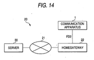
- Fig. 14 is a system diagram for indicating an example of a communication system 20 as the embodiment mode 2.
- the communication system 20 has contained both a server 30 and a homegateway 22 which have been connected to a network 21 such as the Internet connected network, and also, has contained a communication apparatus 1 which has been connected to the homegateway 22.
- a network 21 such as the Internet connected network
- a communication apparatus 1 which has been connected to the homegateway 22.
- an arrangement of the communication apparatus 1 is the same arrangement as the above-described PLC adaptor 1 shown in Fig. 5 , and explanations thereof are omitted.
- both the power line 2 and the electric appliance 3 have been omitted in Fig. 14 .
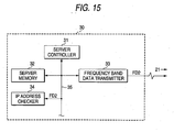
- Fig. 15 is a functional block diagram for representing an example of the server 30.
- the server 30 has contained a server controller 31, and this server controller 31 has been connected via a bus line 35 to a server memory 32, a frequency band data transmitter 33, and an IP address checker 34.
- the frequency band data transmitter 33 has been connected to the network 21.
- the frequency band table FDT shown in Fig. 6 is not stored in the transmitter memory 10 of the PLC adaptor 1, but has been previously stored in the server memory 32 of the sever 30.
- both the server controller 31 and the IP address checker 34 may be realized by an IC (Integrated Circuit) which constitutes a CPU (Central Processing Unit); the server memory 32 may be realized by such a memory as a ROM and a RAM; and the frequency band data transmitter 33 may be realized by a modem which converts a digital signal into an analog signal. Further, the frequency band data transmitter 33 may function as one example of a characteristic value transmitter, and the IP address checker 34 may function as one example of a gateway area information checker.
- IC Integrated Circuit
- CPU Central Processing Unit
- the server memory 32 may be realized by such a memory as a ROM and a RAM
- the frequency band data transmitter 33 may be realized by a modem which converts a digital signal into an analog signal.
- the frequency band data transmitter 33 may function as one example of a characteristic value transmitter
- the IP address checker 34 may function as one example of a gateway area information checker.
- Fig. 16 is a diagram for indicating one example of contents of an address table ADT.
- IP address "IPA” corresponds to, for example, an address which is defined based upon IPv4 (Internet Protocol Version 4). Since such an IP address IPA is arranged by a 32-bit sequence, approximately 43 million pieces of combined sequences are present in total, and IP addresses of a specific range have been allocated to each of areas AR such as countries (for instance, IP addresses defined from “194.0.0.0” through “195.255.255.255” have been allocated to North America) by such an institute as IANA (Internet Assigned Numbers Authority).
- IANA Internet Assigned Numbers Authority
- the IP address checker 34 of the server 30 monitors the IP address IPA set to the PC 3B. In the case that this IP address IPA is changed to be set, this IP address checker 34 refers to the IP address of the PC 3B via the network 21 so as to read out the use area of the communication apparatus 1. Also, as represented in Fig. 16 , an address table "ADT" which indicates the ranges of the IP address IP corresponding to the respective areas AR1, AR2, AR3, ---, has been stored in the server 30.
- the IP address checker 34 refers to the address table ADT which has been stored in the server 30 so as to read out the area “AR2" as such an area “AR” which corresponds to the range of the IP address containing the IP address "IPA2" (namely, as "use area") .
- the IP address checker 34 reads out such a frequency band data FD corresponding to this read area AR2 from the frequency band table FDT (refer to Fig. 6 ) which has been stored in the server memory 32.
- the frequency band data transmitter 33 transmits the read frequency band data FD2 via both the network 21 and the homegateway 22 to the CPU 9 of the communication apparatus 1.
- the CPU 9 shown in Fig. 5 stores the transmitted frequency band data FD2 into the transmitter memory 10 of the communication apparatus 1.
- the controller 8 retrieves the frequency band data FD2 from the transmitter memory 10. Since the acquired frequency band data FD2 indicates the frequency band " ⁇ f2", similar to the embodiment mode 1, the controller 8 issues an instruction to the mapping unit 51 of the transmitter 5 in such a manner that sub-carriers SC2 and SC3 corresponding to the frequency band ⁇ f2 are selected from, for example, 4 sets of the sub-carriers SC1, SC2, SC3, and SC4:
- the frequency band ⁇ f of the transmission signal SS has been changed from " ⁇ f1" to " ⁇ f2" to set the changed frequency band " ⁇ f2.” It should also be noted that since communication operation of the communication apparatus 1 of this embodiment mode 2 is similar to that of the embodiment mode 1, explanations thereof are omitted.
- the server 30 can automatically change the frequency band " ⁇ f” to set the changed frequency band " ⁇ f” without requiring the cumbersome operation by the user of the communication apparatus 1, which is different from the above-explained embodiment mode 1.
- the server 30 stores the frequency band table FDT and transmits the frequency band data FD corresponding to the use area of the communication apparatus 1 to the communication apparatus 1, so that the frequency bands " ⁇ f" as to the respective areas "AR" can be managed on the side of the server 30.
- the IP address "IPA” has been described as one example of the area information indicative of the use area of the communication apparatus 1.
- the present invention is not always limited only to this IP address IPA.
- the IP addresses are not always limited only to such IP addresses which have been especially defined by IPv4, but may be alternatively realized by such addresses which have been defined by IPv6 (Internet Protocol Version 6).
- the embodiment mode 2 has explained such a case that the server 30 monitors the IP address IPA of the electric appliance 3, the present invention is not limited thereto.
- the communication apparatus 1 may monitor the IP address IPA of the electric appliance 3.
- the server 30 may alternatively monitor an IP address "IPA" of another communication apparatus (for instance, gateway) to which the IP address IPA corresponding to the use area of the communication apparatus 1 in order to monitor the IP address IPA of the electric appliance 3.
- another communication apparatus for instance, gateway
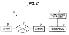
- Fig. 17 is a system diagram for showing one example of a communication system 20 in such a case that an IP address of a gateway is monitored.
- This communication system 20 of Fig. 17 is made different from the communication system 20 shown in Fig. 14 , and a homegateway 22 has been connected via a gateway 23 to a network 21, and further, an IP address checker 34 of the server 30 monitors an IP address IPA set to the gateway 23.
- the address checker 34 of the server 30 refers to the IP address "IPA2" which has been set to the gateway 23 via the network 21, and then, reads out the area "AR2" as the use area of the communication apparatus 1.
- the IP address checker 34 acquires the frequency band data FD2, and then, the frequency band data transmitter 33 of the server 30 transmits the retrieved frequency data FD2 via the network 21, the gateway 23, and the homegateway 22 to the CPU 9 of the communication apparatus 1.
- the frequency band " ⁇ f" of the transmission signal SS is changed from “ ⁇ f1" to " ⁇ f2”, and the changed frequency band " ⁇ f2" is set in a similar manner to the above embodiment mode. Accordingly, the area information which indicates the use area of the communication apparatus 1 need not monitor the communication apparatus 1, so that the degree of freedom as to the monitoring subject can be widened.
- Fig. 14 and Fig. 17 have been disclosed as one example of the communication system 20 in the above-explained embodiment mode 2, the present invention is not limited only to these arrangements.
- the network if the communication apparatus 1 can be freely connected thereto, then the present invention need not be limited only to the Internet connected network.
- an unified digital communication network such as ISDN (Integrated Services Digital Network), an international public network, a cable modem network, a DSL (Digital Subscriber Line) modem network, an FTTH (Fiber to the Home), or such an intranet network which has been individually constituted within an enterprise may be employed as the above-explained network.
- an It (Internet Protocol) layer in an OSI Open System Interconnection
- OSI Open System Interconnection
- an open type broadband network or an intranet network which has been individually constituted within an enterprise may be employed.
- no specific restriction is required for a physical layer, a data link layer, and a network layer.
- the connecting means between the communication apparatus 1 and the network 21 in the communication system 20 if the communication apparatus 1 may be connected to the network 21 by employing at least one of a power line, a copper wire, a twisted wire, a coaxial cable, a wireless line, Ethernet (registered trademark), a telephone line, and the like, then any of these connecting means may be employed, and both sorts of physical layers of interfaces and total quantities thereof are not limited.
- the present invention can be applied to a transmission apparatus for outputting input data as a transmission signal, a transmission method, and a communication system. For instance, even in such a case that a restricted content is changed in connection with an alteration of a law, and even when a use area of a transmission apparatus is changed, the transmission apparatus, the transmission method, and the communication system, according to the present invention, can be properly adapted to a change in characteristic values to be set in a flexible manner.
Landscapes
- Engineering & Computer Science (AREA)
- Power Engineering (AREA)
- Computer Networks & Wireless Communication (AREA)
- Signal Processing (AREA)
- Cable Transmission Systems, Equalization Of Radio And Reduction Of Echo (AREA)
- Transmitters (AREA)
Claims (16)
- Adaptateur (1) de communication sur ligne électrique à utiliser dans une zone d'utilisation (AR2) et pour délivrer en sortie des données d'entrée (SD) en tant que signal de transmission (SS), l'adaptateur comprenant:un dispositif de détermination (8) de valeur caractéristique adapté pour établir une valeur caractéristique (Δf1) indiquant une caractéristique physique du signal de transmission (SS) en conformité avec des informations (FD1) de la valeur caractéristique incluant un ensemble de valeurs caractéristiques prédéterminées stockées dans une mémoire (10);un générateur (5) de signal de transmission pour générer le signal de transmission (SS) ayant la valeur caractéristique (Δf1) établie par le dispositif de détermination (8) de valeur caractéristique à partir des données d'entrée (SD), et pour délivrer en sortie le signal de transmission généré (SS);une section (9) d'obtention de valeur caractéristique pour obtenir, à partir de ladite mémoire (10), des informations (FD2) de valeur caractéristique indiquant une autre valeur caractéristique (Δf2) dudit ensemble de valeurs caractéristiques prédéterminées; etun dispositif de modification (9) de valeur caractéristique pour commander le dispositif de détermination (8) de valeur caractéristique de telle manière que la valeur caractéristique (Δf1) établie par le dispositif de détermination (8) de valeur caractéristique soit changée en ladite une autre valeur caractéristique (Δf2) indiquant les informations (FD2) de valeur caractéristique obtenues par la section (9) d'obtention de valeur caractéristique de manière à établir ladite autre valeur caractéristique (Δf2);de sorte que la valeur caractéristique corresponde à la zone d'utilisation (AR2) dans laquelle l'adaptateur sera utilisé.
- Adaptateur (1) selon la revendication 1, dans lequel:le dispositif de détermination (8) de valeur caractéristique est adapté pour établir une bande de fréquences (Δf1) du signal de transmission (SS);le générateur (5) de signal de transmission est composé de:un sélecteur (51) de sous-porteuses pour sélectionner au moins l'une d'une sous-porteuse (SC2) dans la bande de fréquences (Δf1) établie par le dispositif de détermination (8) de valeur caractéristique;un générateur (51) de données binaires pour générer une pluralité de données binaires (BL) à partir des données d'entrée (SD); etun dispositif (51) de mappage de symboles pour mapper les données binaires (BL) respectives générées par le générateur (51) de données binaires en tant que symboles modulés (PAM) uniquement par rapport à la sous-porteuse (SC2) sélectionnée par le sélecteur (51) de sous-porteuses; etle générateur (51) de signal de transmission génère le signal de transmission (SS), et délivre en sortie le signal de transmission (SS) généré sur la base des symboles modulés numériques (PAM) mappés par le dispositif (51) de mappage de symboles;la section (9) d'obtention de valeur caractéristique obtient des informations (FD2) de valeur caractéristique indiquant une autre bande de fréquences (Δf2); et où:le dispositif de modification (9) de valeur caractéristique commande le dispositif de détermination (8) de valeur caractéristique de telle manière que la bande de fréquences (Δf1) établie par le dispositif de détermination (8) de valeur caractéristique soit changée en une autre bande de fréquences (Δf2) indiquant la valeur caractéristique (FD2) obtenue par la section (9) d'obtention de valeur caractéristique de manière à établir la bande de fréquences (Δf2) changée.
- Adaptateur (1) selon la revendication 2 dans lequel:le générateur (5) de signal de transmission comprend en plus:un transformateur (52) inverse d'ondelettes pour transformer en ondelettes les symboles modulés numériques (PD) mappés par le dispositif (51) de mappage de symboles en données (TD) sérielles de forme d'onde temporelles; etle générateur (5) de signal de transmission génère le signal de transmission (SS) à partir des données (TD) sérielles de forme d'onde temporelles générées par le transformateur (52) inverse d'ondelettes, et délivre en sortie le signal de transmission (SS) généré.
- Adaptateur (1) selon la revendication 1 dans lequel:le dispositif de détermination (8) de valeur caractéristique est adapté pour établir un niveau de puissance du signal de transmission (SS);le générateur (5) de signal de transmission comprend en plus:un amplificateur (54) pour commander le niveau de puissance du signal de transmission (SS) au niveau de puissance établi par le dispositif de détermination (8) de valeur caractéristique; et le générateur (5) de signal de transmission génère un signal de transmission (SS) ayant le niveau de puissance commandé par l'amplificateur (54) à partir des données d'entrée (SD); et délivre en sortie le signal de transmission (SS) généré;la section (9) d'obtention de valeur caractéristique obtient des informations de valeur caractéristique indiquant un autre niveau de puissance; et où:le dispositif (9) de modification de valeur caractéristique commande le dispositif de détermination (8) de valeur caractéristique de telle manière quele niveau de puissance établi par le dispositif de détermination (8) de valeur caractéristique est changé en un autre niveau de puissance indiqué par les informations de valeur caractéristique obtenues par la section (9) d'obtention de valeur caractéristique.
- Adaptateur (1) selon la revendication 1 dans lequel:le générateur (5) de signal de transmission délivre en sortie le signal de transmission (SS) généré à travers une ligne électrique (2).
- Adaptateur (1) selon la revendication 1 dans lequel:l'appareil de transmission (1) comprend en plus:une mémoire (10) de l'émetteur pour y stocker un tableau (FDT) d'informations de valeurs caractéristiques qui indique les informations (FD) de valeurs caractéristiques qui correspondent à une zone (AR); etla section (9) d'obtention de valeur caractéristique obtient les informations (FD2) de valeurs caractéristiques qui correspondent à la zone d'utilisation (AR2) de l'appareil de transmission(1) à partir du tableau (FDT) d'informations de valeurs caractéristiques.
- Adaptateur (1) selon la revendication 6 dans lequel:l'appareil de transmission (1) comprend en plus:une unité (11) d'entrée de signal pour accepter un signal pour désigner la zone d'utilisation (AR2) de l'appareil de transmission (1); etla section (9) d'obtention de valeur caractéristique obtient des informations (FD2) de valeurs caractéristiques qui correspondent à la zone d'utilisation (AR2) désignée à travers l'unité (11) d'entrée de signal à partir du tableau (FDT) d'informations de valeurs caractéristiques.
- Adaptateur (1) selon la revendication 6 dans lequel:l'appareil de transmission (1) comprend en plus:un dispositif de vérification (9) d'informations de zone pour contrôler des informations de zone (IPA) qui indiquent la zone d'utilisation (AR2) de l'appareil de transmission (1); etau cas où les informations de zone (IPA) de l'appareil de transmission (1) contrôlées par le dispositif de vérification (9) d'informations de zone sont mises à jour (IP2), la section (9) d'obtention de valeur caractéristique obtient des informations de valeurs caractéristiques qui correspondent à une zone d'utilisation (AR2) des informations de zone (IPA2) à partir du tableau (FDT) d'informations de valeurs caractéristiques.
- Système de communication équipé d'un serveur (30) et de l'adaptateur (1) selon la revendication 1, qui est relié à un réseau (21), dans lequel:le serveur (30) comprend:une mémoire (32) de serveur pour y stocker le tableau (FDT) d'informations de valeurs caractéristiques qui indique les informations (FD) de valeurs caractéristiques qui correspondent à la zone d'utilisation (AR); etun émetteur (33) de valeur caractéristique pour lire les informations (FD2) de valeurs caractéristiques correspondant à la zone d'utilisation (AR2) de l'appareil de transmission (1) à partir du tableau (FDT) d'informations de valeurs caractéristiques, et émet les informations (FD2) de valeurs caractéristiques lues à la section (9) d'obtention de valeur caractéristique de l'appareil de transmission (1).
- Système de communication selon la revendication 9 dans lequel:l'adaptateur (1) est relié à travers une passerelle (22) au réseau (21);le serveur (30) est composé de:un dispositif de vérification (9) d'informations de zone pour contrôler des informations de zone (IPA) établies à la passerelle (22); etau cas où les informations de zone (IPA) de la passerelle (22) contrôlées par le dispositif de vérification (9) d'informations de zone sont mises à jour (IPA2), l'émetteur (33) de valeur caractéristique du serveur (30) lit les informations de caractéristiques (FD2) qui correspondent à une zone d'utilisation (AR2) des informations de zone (IPA2) à partir du tableau (FDT) d'informations de valeurs caractéristiques en tant qu'informations de valeurs caractéristiques (FD2) qui correspondent à la zone d'utilisation (AR2) de l'appareil de transmission (1), et l'émetteur (33) de valeur caractéristique émet les informations (FD2) de valeurs caractéristiques lues à la section (9) d'obtention de valeur caractéristique de l'appareil de transmission (1).
- Procédé pour actionner un adaptateur (1) de communication sur ligne électrique à utiliser dans une zone d'utilisation (AR2) et pour délivrer en sortie des données d'entrée (SD) en tant que signal de transmission (SS), comprenant le fait de:établir une valeur caractéristique (Δf1) indiquant une caractéristique physique du signal de transmission (SS) en conformité avec des informations (FD1) de valeurs caractéristiques incluant un ensemble de valeurs caractéristiques prédéterminées stockées dans une mémoire (10);générer à partir des données d'entrée (SD) le signal de transmission (SS) ayant la valeur caractéristique (Δf1) établie;obtenir à partir de ladite mémoire (10) des informations (FD2) de valeurs caractéristiques indiquant une autre valeur caractéristique (Δf2) dudit ensemble de valeurs caractéristiques prédéterminées; etchanger à l'appareil de transmission (1) la valeur caractéristique (Δf1) établie en ladite une autre valeur caractéristique (Δf2) indiquant les informations (FD2) de valeurs caractéristiques obtenues,moyen par lequel la valeur caractéristique correspond à la zone d'utilisation (AR2) dans laquelle l'adaptateur sera utilisé.
- Adaptateur (1) selon la revendication 1, dans lequel ladite mémoire (10) comprend une première partie située dans ledit appareil de transmission (1) et une deuxième partie située à l'extérieur dudit appareil de transmission (1).
- Adaptateur (1) selon la revendication 1, dans lequel ladite mémoire (10) est située dans ledit appareil de transmission (1).
- Adaptateur (1) selon la revendication 1, dans lequel ladite mémoire (10) est située à l'extérieur dudit appareil de transmission (1).
- Adaptateur (1) selon la revendication 1, dans lequel lesdites informations (FD1) de valeur caractéristique se rapportent à l'une de différentes normes de communication établies par un pays donné ou de différentes normes de communication établies par différents pays.
- Système comprenant un ordinateur et l'adaptateur (1) selon la revendication 1.
Applications Claiming Priority (2)
| Application Number | Priority Date | Filing Date | Title |
|---|---|---|---|
| JP2004214059A JP5052742B2 (ja) | 2004-07-22 | 2004-07-22 | 送信装置及びそれを用いた通信システム |
| PCT/JP2005/013788 WO2006009306A1 (fr) | 2004-07-22 | 2005-07-21 | Appareil de transmission et systeme de communication utilisant cet appareil |
Publications (2)
| Publication Number | Publication Date |
|---|---|
| EP1774672A1 EP1774672A1 (fr) | 2007-04-18 |
| EP1774672B1 true EP1774672B1 (fr) | 2009-11-04 |
Family
ID=35005846
Family Applications (1)
| Application Number | Title | Priority Date | Filing Date |
|---|---|---|---|
| EP05767337A Expired - Lifetime EP1774672B1 (fr) | 2004-07-22 | 2005-07-21 | Appareil de transmission et systeme de communication utilisant cet appareil |
Country Status (6)
| Country | Link |
|---|---|
| US (1) | US7197080B2 (fr) |
| EP (1) | EP1774672B1 (fr) |
| JP (1) | JP5052742B2 (fr) |
| AT (1) | ATE447796T1 (fr) |
| DE (1) | DE602005017498D1 (fr) |
| WO (1) | WO2006009306A1 (fr) |
Families Citing this family (9)
| Publication number | Priority date | Publication date | Assignee | Title |
|---|---|---|---|---|
| JP5052742B2 (ja) * | 2004-07-22 | 2012-10-17 | パナソニック株式会社 | 送信装置及びそれを用いた通信システム |
| JP2006352267A (ja) * | 2005-06-13 | 2006-12-28 | Matsushita Electric Ind Co Ltd | 送信装置及び受信装置並びに送信方法及び受信方法 |
| JP5094004B2 (ja) * | 2005-10-20 | 2012-12-12 | パナソニック株式会社 | データ中継装置及びデータ中継方法 |
| EP2154789B1 (fr) * | 2008-08-11 | 2019-10-02 | Sony Corporation | Procédé pour détecter une entrée de signal radio à ondes courtes dans un système de communication par ligne électrique et modem de communication électrique |
| US8674823B1 (en) | 2009-05-12 | 2014-03-18 | Plug ID, LLC. | Power management system |
| JP2014143452A (ja) * | 2011-05-13 | 2014-08-07 | Panasonic Corp | 電力線通信装置、集積回路、および電力線通信方法 |
| US20130051268A1 (en) * | 2011-08-29 | 2013-02-28 | Texas Instruments Incorporated | Carrier Sense Multiple Access (CSMA) and Collision Detection for Power Line Communications (PLC) Using a Noise Model |
| JP6450142B2 (ja) * | 2014-10-17 | 2019-01-09 | 株式会社日立製作所 | 電力系統制御システム、電力系統制御方法、および電力変換装置 |
| US9559880B1 (en) * | 2016-03-04 | 2017-01-31 | Inphi Corporation | Eye modulation for pulse-amplitude modulation communication systems |
Family Cites Families (36)
| Publication number | Priority date | Publication date | Assignee | Title |
|---|---|---|---|---|
| JPH0226169A (ja) * | 1988-07-15 | 1990-01-29 | Toshiba Corp | ファクシミリ装置 |
| JPH02161830A (ja) * | 1988-12-14 | 1990-06-21 | Nec Corp | データ通信用モデム |
| EP0640265B1 (fr) * | 1992-05-12 | 1998-03-04 | Nokia (Deutschland) GmbH | Systeme de transmission pour la transmission d'un signal utile module sur une porteuse |
| US5995539A (en) * | 1993-03-17 | 1999-11-30 | Miller; William J. | Method and apparatus for signal transmission and reception |
| US5497398A (en) * | 1993-08-12 | 1996-03-05 | Aware, Inc. | Multi-carrier transceiver |
| US5636246A (en) * | 1994-11-16 | 1997-06-03 | Aware, Inc. | Multicarrier transmission system |
| US5631610A (en) * | 1996-01-25 | 1997-05-20 | Aware, Inc. | Single side-band modulation system for use in digitally implemented multicarrier transmission systems |
| US5903594A (en) * | 1997-04-16 | 1999-05-11 | General Electric Company | Power line communications spread spectrum protocol |
| DK1021901T3 (da) * | 1997-10-10 | 2010-03-08 | Daphimo Co B V Llc | Splitterløst multibærermodem |
| US6229432B1 (en) * | 1997-10-30 | 2001-05-08 | Duane Patrick Fridley | Intelligent transceiver module particularly suited for power line control systems |
| US6434119B1 (en) * | 1998-03-19 | 2002-08-13 | Texas Instruments Incorporated | Initializing communications in systems using multi-carrier modulation |
| US5991269A (en) * | 1998-09-15 | 1999-11-23 | Northern Telecom Limited | Wireline modem, communication system and method of setting-up such |
| JP3596321B2 (ja) * | 1998-09-21 | 2004-12-02 | 三菱電機株式会社 | 電力線搬送通信装置及びその通信制御方法 |
| DE69902623T2 (de) | 1999-03-25 | 2003-04-10 | Kabushiki Kaisha Toshiba, Kawasaki | Zwischenverstärker eines OFDM-Übertragungssignals |
| JP2000278237A (ja) | 1999-03-25 | 2000-10-06 | Toshiba Corp | Ofdm用中継装置 |
| DE69942933D1 (de) | 1999-09-30 | 2010-12-23 | St Microelectronics Srl | Pegelregulierung eines Signals, das von einem Sense-Empfänger produziert wird, der an eine Stromleitung angeschlossenen ist |
| US6442129B1 (en) * | 1999-12-06 | 2002-08-27 | Intellon Corporation | Enhanced channel estimation |
| DE60038868D1 (de) * | 2000-03-07 | 2008-06-26 | Alcatel Lucent | Verfahren zur Bestimmung einer Eigenschaft eines Kanals und Diskreter-Wavelet Empfänger zur Durchführung des Verfahrens |
| US6456192B1 (en) * | 2000-04-19 | 2002-09-24 | Phonex Broadband Corporation | Method and system for power line null detection and automatic frequency and gain control |
| JP4511783B2 (ja) * | 2000-06-26 | 2010-07-28 | パナソニック株式会社 | 無線通信装置、無線通信システムおよび無線通信方法 |
| ES2188373B1 (es) | 2001-05-25 | 2004-10-16 | Diseño De Sistemas En Silencio, S.A. | Procedimiento de optimizacion de la comunicacion para sistema de transmision digital ofdm multiusuario sobre red electrica. |
| JP4822038B2 (ja) * | 2001-08-28 | 2011-11-24 | 大日本印刷株式会社 | ディスクリート用パッケージ及びその製造方法並びにそれに用いるリードフレーム |
| ES2550821T3 (es) * | 2002-01-24 | 2015-11-12 | Panasonic Corporation | Método de y sistema para comunicaciones de portadora por línea eléctrica |
| JP3931666B2 (ja) * | 2002-01-24 | 2007-06-20 | 松下電器産業株式会社 | 電力線搬送通信装置 |
| JP4122789B2 (ja) * | 2002-02-13 | 2008-07-23 | 日本電気株式会社 | 複合無線装置及びそれに用いる干渉回避制御方法 |
| JP4516714B2 (ja) * | 2002-04-05 | 2010-08-04 | 株式会社ケンウッド | データ配信システム、受信端末、データ配信方法、及び、プログラム |
| JP2003347943A (ja) * | 2002-05-29 | 2003-12-05 | Alps Electric Co Ltd | カード型無線lan |
| US7164724B2 (en) | 2002-09-25 | 2007-01-16 | Matsushita Electric Industrial Co., Ltd. | Communication apparatus |
| DE50212642D1 (de) * | 2002-11-15 | 2008-09-25 | Abb Research Ltd | Konfigurationssystem für Netzwerkgeräte und Verfahren zum Rekonfigurieren von Geräten |
| WO2004075502A2 (fr) * | 2003-02-19 | 2004-09-02 | Matsushita Electric Industrial Co. Ltd. | Appareil et procede de reception pour transmission numerique a porteuses multiples |
| EP1639774B1 (fr) * | 2003-06-18 | 2009-06-03 | Panasonic Corporation | Procede et appareil pour la reception de signaux multiporteuses numeriques faisant appel a une transformation en ondelettes |
| WO2005004426A1 (fr) * | 2003-07-03 | 2005-01-13 | Matsushita Electric Industrial Co., Ltd. | Emetteur et procede d'emission multiporteuse numerique utilisant des ondelettes |
| EP1499033B1 (fr) * | 2003-07-16 | 2007-03-28 | Sony Deutschland GmbH | Détection de signaux de radiodiffusion pour définir les bandes de fréquence utilisables pour la communication par courants porteurs |
| JP4356392B2 (ja) * | 2003-08-07 | 2009-11-04 | パナソニック株式会社 | 通信装置 |
| US7715425B2 (en) | 2004-02-26 | 2010-05-11 | Atheros Communications, Inc. | Channel adaptation synchronized to periodically varying channel |
| JP5052742B2 (ja) * | 2004-07-22 | 2012-10-17 | パナソニック株式会社 | 送信装置及びそれを用いた通信システム |
-
2004
- 2004-07-22 JP JP2004214059A patent/JP5052742B2/ja not_active Expired - Fee Related
-
2005
- 2005-07-20 US US11/185,032 patent/US7197080B2/en not_active Expired - Lifetime
- 2005-07-21 AT AT05767337T patent/ATE447796T1/de not_active IP Right Cessation
- 2005-07-21 DE DE602005017498T patent/DE602005017498D1/de not_active Expired - Lifetime
- 2005-07-21 EP EP05767337A patent/EP1774672B1/fr not_active Expired - Lifetime
- 2005-07-21 WO PCT/JP2005/013788 patent/WO2006009306A1/fr not_active Ceased
Also Published As
| Publication number | Publication date |
|---|---|
| JP5052742B2 (ja) | 2012-10-17 |
| EP1774672A1 (fr) | 2007-04-18 |
| US7197080B2 (en) | 2007-03-27 |
| US20060018399A1 (en) | 2006-01-26 |
| ATE447796T1 (de) | 2009-11-15 |
| WO2006009306A1 (fr) | 2006-01-26 |
| DE602005017498D1 (de) | 2009-12-17 |
| JP2006041591A (ja) | 2006-02-09 |
Similar Documents
| Publication | Publication Date | Title |
|---|---|---|
| US8451879B2 (en) | High bandwidth data transport system | |
| US7961705B2 (en) | High bandwidth data transport system | |
| KR101413314B1 (ko) | 선로를 통해 무선기반 신호를 전송하기 위한 시스템 및방법 | |
| US7545868B2 (en) | High bandwidth data transport system | |
| US8442130B2 (en) | Communication apparatus, communication method and integrated circuit | |
| US7912139B2 (en) | Multi-carrier communication apparatus, power line communication circuit, and multi-carrier communication method | |
| US20020010870A1 (en) | Method and apparatus for dual-band modulation in powerline communication network systems | |
| WO2011022464A2 (fr) | Code de répétition concaténé avec un code convolutionnel | |
| US20120236879A1 (en) | Coexistence in communication system | |
| US20090060061A1 (en) | Communication apparatus, communication method, and integrated circuit | |
| CN101884211A (zh) | 宽带信号的传输 | |
| EP1774672B1 (fr) | Appareil de transmission et systeme de communication utilisant cet appareil | |
| US20020159512A1 (en) | Communication apparatus and communication method | |
| WO2007100633A2 (fr) | Système de transport de données à grande largeur de bande | |
| JP4895557B2 (ja) | マルチキャリア通信装置、及びマルチキャリア通信方法 | |
| JP4973788B2 (ja) | 送信装置及びそれを用いた通信システム | |
| CN112565116B (zh) | 一种信号处理方法、通信芯片以及通信装置 | |
| JP3758035B2 (ja) | データ伝送装置 | |
| CN102158333B (zh) | 用于在布线上传送基于无线的信号的系统和方法 | |
| JP2007281577A (ja) | マルチキャリア受信装置及びマルチキャリア受信方法 | |
| US20040001587A1 (en) | xDSL interconnecting device and communication system |
Legal Events
| Date | Code | Title | Description |
|---|---|---|---|
| PUAI | Public reference made under article 153(3) epc to a published international application that has entered the european phase |
Free format text: ORIGINAL CODE: 0009012 |
|
| 17P | Request for examination filed |
Effective date: 20070222 |
|
| AK | Designated contracting states |
Kind code of ref document: A1 Designated state(s): AT BE BG CH CY CZ DE DK EE ES FI FR GB GR HU IE IS IT LI LT LU LV MC NL PL PT RO SE SI SK TR |
|
| 17Q | First examination report despatched |
Effective date: 20070618 |
|
| DAX | Request for extension of the european patent (deleted) | ||
| RAP1 | Party data changed (applicant data changed or rights of an application transferred) |
Owner name: PANASONIC CORPORATION |
|
| GRAP | Despatch of communication of intention to grant a patent |
Free format text: ORIGINAL CODE: EPIDOSNIGR1 |
|
| GRAS | Grant fee paid |
Free format text: ORIGINAL CODE: EPIDOSNIGR3 |
|
| GRAA | (expected) grant |
Free format text: ORIGINAL CODE: 0009210 |
|
| AK | Designated contracting states |
Kind code of ref document: B1 Designated state(s): AT BE BG CH CY CZ DE DK EE ES FI FR GB GR HU IE IS IT LI LT LU LV MC NL PL PT RO SE SI SK TR |
|
| REG | Reference to a national code |
Ref country code: GB Ref legal event code: FG4D |
|
| REG | Reference to a national code |
Ref country code: CH Ref legal event code: EP |
|
| REG | Reference to a national code |
Ref country code: IE Ref legal event code: FG4D |
|
| REF | Corresponds to: |
Ref document number: 602005017498 Country of ref document: DE Date of ref document: 20091217 Kind code of ref document: P |
|
| NLV1 | Nl: lapsed or annulled due to failure to fulfill the requirements of art. 29p and 29m of the patents act | ||
| LTIE | Lt: invalidation of european patent or patent extension |
Effective date: 20091104 |
|
| PG25 | Lapsed in a contracting state [announced via postgrant information from national office to epo] |
Ref country code: IS Free format text: LAPSE BECAUSE OF FAILURE TO SUBMIT A TRANSLATION OF THE DESCRIPTION OR TO PAY THE FEE WITHIN THE PRESCRIBED TIME-LIMIT Effective date: 20100304 Ref country code: LT Free format text: LAPSE BECAUSE OF FAILURE TO SUBMIT A TRANSLATION OF THE DESCRIPTION OR TO PAY THE FEE WITHIN THE PRESCRIBED TIME-LIMIT Effective date: 20091104 Ref country code: ES Free format text: LAPSE BECAUSE OF FAILURE TO SUBMIT A TRANSLATION OF THE DESCRIPTION OR TO PAY THE FEE WITHIN THE PRESCRIBED TIME-LIMIT Effective date: 20100215 Ref country code: PT Free format text: LAPSE BECAUSE OF FAILURE TO SUBMIT A TRANSLATION OF THE DESCRIPTION OR TO PAY THE FEE WITHIN THE PRESCRIBED TIME-LIMIT Effective date: 20100304 Ref country code: SE Free format text: LAPSE BECAUSE OF FAILURE TO SUBMIT A TRANSLATION OF THE DESCRIPTION OR TO PAY THE FEE WITHIN THE PRESCRIBED TIME-LIMIT Effective date: 20091104 Ref country code: FI Free format text: LAPSE BECAUSE OF FAILURE TO SUBMIT A TRANSLATION OF THE DESCRIPTION OR TO PAY THE FEE WITHIN THE PRESCRIBED TIME-LIMIT Effective date: 20091104 |
|
| PG25 | Lapsed in a contracting state [announced via postgrant information from national office to epo] |
Ref country code: SI Free format text: LAPSE BECAUSE OF FAILURE TO SUBMIT A TRANSLATION OF THE DESCRIPTION OR TO PAY THE FEE WITHIN THE PRESCRIBED TIME-LIMIT Effective date: 20091104 Ref country code: LV Free format text: LAPSE BECAUSE OF FAILURE TO SUBMIT A TRANSLATION OF THE DESCRIPTION OR TO PAY THE FEE WITHIN THE PRESCRIBED TIME-LIMIT Effective date: 20091104 Ref country code: PL Free format text: LAPSE BECAUSE OF FAILURE TO SUBMIT A TRANSLATION OF THE DESCRIPTION OR TO PAY THE FEE WITHIN THE PRESCRIBED TIME-LIMIT Effective date: 20091104 Ref country code: CY Free format text: LAPSE BECAUSE OF FAILURE TO SUBMIT A TRANSLATION OF THE DESCRIPTION OR TO PAY THE FEE WITHIN THE PRESCRIBED TIME-LIMIT Effective date: 20091104 |
|
| PG25 | Lapsed in a contracting state [announced via postgrant information from national office to epo] |
Ref country code: BE Free format text: LAPSE BECAUSE OF FAILURE TO SUBMIT A TRANSLATION OF THE DESCRIPTION OR TO PAY THE FEE WITHIN THE PRESCRIBED TIME-LIMIT Effective date: 20091104 Ref country code: AT Free format text: LAPSE BECAUSE OF FAILURE TO SUBMIT A TRANSLATION OF THE DESCRIPTION OR TO PAY THE FEE WITHIN THE PRESCRIBED TIME-LIMIT Effective date: 20091104 |
|
| PG25 | Lapsed in a contracting state [announced via postgrant information from national office to epo] |
Ref country code: DK Free format text: LAPSE BECAUSE OF FAILURE TO SUBMIT A TRANSLATION OF THE DESCRIPTION OR TO PAY THE FEE WITHIN THE PRESCRIBED TIME-LIMIT Effective date: 20091104 Ref country code: RO Free format text: LAPSE BECAUSE OF FAILURE TO SUBMIT A TRANSLATION OF THE DESCRIPTION OR TO PAY THE FEE WITHIN THE PRESCRIBED TIME-LIMIT Effective date: 20091104 Ref country code: EE Free format text: LAPSE BECAUSE OF FAILURE TO SUBMIT A TRANSLATION OF THE DESCRIPTION OR TO PAY THE FEE WITHIN THE PRESCRIBED TIME-LIMIT Effective date: 20091104 Ref country code: BG Free format text: LAPSE BECAUSE OF FAILURE TO SUBMIT A TRANSLATION OF THE DESCRIPTION OR TO PAY THE FEE WITHIN THE PRESCRIBED TIME-LIMIT Effective date: 20100204 |
|
| PG25 | Lapsed in a contracting state [announced via postgrant information from national office to epo] |
Ref country code: CZ Free format text: LAPSE BECAUSE OF FAILURE TO SUBMIT A TRANSLATION OF THE DESCRIPTION OR TO PAY THE FEE WITHIN THE PRESCRIBED TIME-LIMIT Effective date: 20091104 Ref country code: SK Free format text: LAPSE BECAUSE OF FAILURE TO SUBMIT A TRANSLATION OF THE DESCRIPTION OR TO PAY THE FEE WITHIN THE PRESCRIBED TIME-LIMIT Effective date: 20091104 |
|
| PLBE | No opposition filed within time limit |
Free format text: ORIGINAL CODE: 0009261 |
|
| STAA | Information on the status of an ep patent application or granted ep patent |
Free format text: STATUS: NO OPPOSITION FILED WITHIN TIME LIMIT |
|
| 26N | No opposition filed |
Effective date: 20100805 |
|
| PG25 | Lapsed in a contracting state [announced via postgrant information from national office to epo] |
Ref country code: GR Free format text: LAPSE BECAUSE OF FAILURE TO SUBMIT A TRANSLATION OF THE DESCRIPTION OR TO PAY THE FEE WITHIN THE PRESCRIBED TIME-LIMIT Effective date: 20100205 |
|
| PG25 | Lapsed in a contracting state [announced via postgrant information from national office to epo] |
Ref country code: MC Free format text: LAPSE BECAUSE OF NON-PAYMENT OF DUE FEES Effective date: 20100731 |
|
| REG | Reference to a national code |
Ref country code: CH Ref legal event code: PL |
|
| PG25 | Lapsed in a contracting state [announced via postgrant information from national office to epo] |
Ref country code: IT Free format text: LAPSE BECAUSE OF FAILURE TO SUBMIT A TRANSLATION OF THE DESCRIPTION OR TO PAY THE FEE WITHIN THE PRESCRIBED TIME-LIMIT Effective date: 20091104 |
|
| PG25 | Lapsed in a contracting state [announced via postgrant information from national office to epo] |
Ref country code: CH Free format text: LAPSE BECAUSE OF NON-PAYMENT OF DUE FEES Effective date: 20100731 Ref country code: LI Free format text: LAPSE BECAUSE OF NON-PAYMENT OF DUE FEES Effective date: 20100731 |
|
| PG25 | Lapsed in a contracting state [announced via postgrant information from national office to epo] |
Ref country code: IE Free format text: LAPSE BECAUSE OF NON-PAYMENT OF DUE FEES Effective date: 20100721 |
|
| PG25 | Lapsed in a contracting state [announced via postgrant information from national office to epo] |
Ref country code: HU Free format text: LAPSE BECAUSE OF FAILURE TO SUBMIT A TRANSLATION OF THE DESCRIPTION OR TO PAY THE FEE WITHIN THE PRESCRIBED TIME-LIMIT Effective date: 20100505 Ref country code: NL Free format text: LAPSE BECAUSE OF FAILURE TO SUBMIT A TRANSLATION OF THE DESCRIPTION OR TO PAY THE FEE WITHIN THE PRESCRIBED TIME-LIMIT Effective date: 20091104 Ref country code: LU Free format text: LAPSE BECAUSE OF NON-PAYMENT OF DUE FEES Effective date: 20100721 |
|
| PG25 | Lapsed in a contracting state [announced via postgrant information from national office to epo] |
Ref country code: TR Free format text: LAPSE BECAUSE OF FAILURE TO SUBMIT A TRANSLATION OF THE DESCRIPTION OR TO PAY THE FEE WITHIN THE PRESCRIBED TIME-LIMIT Effective date: 20091104 |
|
| REG | Reference to a national code |
Ref country code: FR Ref legal event code: PLFP Year of fee payment: 11 |
|
| PGFP | Annual fee paid to national office [announced via postgrant information from national office to epo] |
Ref country code: GB Payment date: 20150715 Year of fee payment: 11 Ref country code: DE Payment date: 20150714 Year of fee payment: 11 |
|
| PGFP | Annual fee paid to national office [announced via postgrant information from national office to epo] |
Ref country code: FR Payment date: 20150629 Year of fee payment: 11 |
|
| REG | Reference to a national code |
Ref country code: DE Ref legal event code: R119 Ref document number: 602005017498 Country of ref document: DE |
|
| GBPC | Gb: european patent ceased through non-payment of renewal fee |
Effective date: 20160721 |
|
| PG25 | Lapsed in a contracting state [announced via postgrant information from national office to epo] |
Ref country code: DE Free format text: LAPSE BECAUSE OF NON-PAYMENT OF DUE FEES Effective date: 20170201 Ref country code: FR Free format text: LAPSE BECAUSE OF NON-PAYMENT OF DUE FEES Effective date: 20160801 |
|
| REG | Reference to a national code |
Ref country code: FR Ref legal event code: ST Effective date: 20170331 |
|
| PG25 | Lapsed in a contracting state [announced via postgrant information from national office to epo] |
Ref country code: GB Free format text: LAPSE BECAUSE OF NON-PAYMENT OF DUE FEES Effective date: 20160721 |