EP1774941A2 - Embase et système pour recevoir et sécuriser un fauteuil roulant dans un véhicule - Google Patents
Embase et système pour recevoir et sécuriser un fauteuil roulant dans un véhicule Download PDFInfo
- Publication number
- EP1774941A2 EP1774941A2 EP06445066A EP06445066A EP1774941A2 EP 1774941 A2 EP1774941 A2 EP 1774941A2 EP 06445066 A EP06445066 A EP 06445066A EP 06445066 A EP06445066 A EP 06445066A EP 1774941 A2 EP1774941 A2 EP 1774941A2
- Authority
- EP
- European Patent Office
- Prior art keywords
- base unit
- wheelchair
- support surface
- vehicle
- floor
- Prior art date
- Legal status (The legal status is an assumption and is not a legal conclusion. Google has not performed a legal analysis and makes no representation as to the accuracy of the status listed.)
- Granted
Links
Images


Classifications
-
- A—HUMAN NECESSITIES
- A61—MEDICAL OR VETERINARY SCIENCE; HYGIENE
- A61G—TRANSPORT, PERSONAL CONVEYANCES, OR ACCOMMODATION SPECIALLY ADAPTED FOR PATIENTS OR DISABLED PERSONS; OPERATING TABLES OR CHAIRS; CHAIRS FOR DENTISTRY; FUNERAL DEVICES
- A61G3/00—Ambulance aspects of vehicles; Vehicles with special provisions for transporting patients or disabled persons, or their personal conveyances, e.g. for facilitating access of, or for loading, wheelchairs
- A61G3/08—Accommodating or securing wheelchairs or stretchers
- A61G3/0808—Accommodating or securing wheelchairs
-
- A—HUMAN NECESSITIES
- A61—MEDICAL OR VETERINARY SCIENCE; HYGIENE
- A61G—TRANSPORT, PERSONAL CONVEYANCES, OR ACCOMMODATION SPECIALLY ADAPTED FOR PATIENTS OR DISABLED PERSONS; OPERATING TABLES OR CHAIRS; CHAIRS FOR DENTISTRY; FUNERAL DEVICES
- A61G3/00—Ambulance aspects of vehicles; Vehicles with special provisions for transporting patients or disabled persons, or their personal conveyances, e.g. for facilitating access of, or for loading, wheelchairs
- A61G3/08—Accommodating or securing wheelchairs or stretchers
Definitions
- the invention relates to a base unit for docking and securing a wheelchair in a vehicle of the type described in the preamble to Claim 1.
- the invention also relates to a system comprising such a base unit.
- the base unit can be used to make it possible to dock and secure wheelchairs at a driver's position or passenger's positions in a vehicle and can be mounted in the vehicle during manufacture or as a retrofit.
- the purpose of the docking systems is to secure the wheelchair in the vehicle.
- the systems normally comprise a base unit that is mounted on the floor of the vehicle at the location of the driver's seat or any one of the passenger seats, after the ordinary seat has been removed from this location.
- the systems also comprise an engaging device that is mounted on the wheelchair.
- the docking is normally thereafter achieved by the wheelchair being driven further forward so that a part of the chassis of the wheelchair is located over the base unit, whereupon the engaging device that projects downwards from the wheelchair engages with a locking mechanism in the base unit.
- the fixing must be strong, so that the very large forces on the wheelchair that can arise in the event of a collision are unable to break the fixing and cause the wheelchair to become loose.
- the fixing should be a butt contact, that is, it should permit as little relative movement as possible between the wheelchair and the vehicle. The greater such relative movement that is possible, the greater the risk that the person in the wheelchair will hit the steering wheel, for example, or some other part of the vehicle in the event of a collision.
- the large moving mass of the combined weight of the wheelchair and the person that would arise in the event of such a relative movement would cause an additional load on the engaging parts of the docking system, which could result in the fixing being broken.
- an additional desirable characteristic of the docking systems is that the wheelchair's clearance above the ground should not be affected adversely when the wheelchair is to be used normally outside the vehicle. It is generally recognized that a good clearance is of the greatest importance for giving the person in the wheelchair good freedom of movement in both rural and urban environments.
- the engaging devices on the wheelchair often consist of an engaging nose or the like that is attached in such a way that it projects downwards from the chassis of the wheelchair, which reduces the clearance considerably and as a result restricts access to some locations.
- US 4,690,364 describes a device for securing a wheelchair in a vehicle.
- the device comprises a base unit that is fixed to the floor of the vehicle and that has a locking mechanism.
- the device also comprises an engaging nose that is attached to a wheelchair by means of a framework in such a way that it does not move. When the framework is screwed onto the chassis of the wheelchair, the engaging nose projects downwards in order to be able to engage with the locking mechanism in the base unit.
- An object of the present invention is therefore to provide a base unit for docking and securing a wheelchair in a vehicle, which base unit contributes to increased safety for the user of the wheelchair when the wheelchair is secured in the vehicle.
- Another object is to provide such a base unit that contributes to achieving a butt fixing of the wheelchair in the vehicle.
- Yet another object is to provide such a base unit that is simple to use and that enables docking and disconnection to be carried out in a simple way.
- Yet another object is to provide such a base unit that has a simple construction and is strong and resistant to wear.
- a base unit of the type described in the introductory part of Claim 1 that has the special technical features described in the characterizing part of the claim. Due to the first support surface arranged on the base unit, which in the docked position supports the wheelchair by making contact with a corresponding first support surface on the wheelchair, the wheelchair's suspension is unloaded and movement of the wheelchair downwards in relation to the vehicle is prevented, whereby the abovementioned problems that are associated with such relative movement are reduced.
- the invention also relates to a system for docking and securing of a wheelchair in a vehicle according to Claim 10.
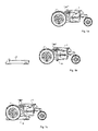
- Figure 1a shows a wheelchair 1 in normal use.
- the seat of the wheelchair has been omitted in the figures for increased clarity.
- the wheelchair has normal clearance without parts projecting down from the chassis. In this position, the wheelchair thus fulfils international requirements concerning clearance above ground level.
- Figure 1b shows the wheelchair when it is moving towards a base unit 2 comprised in a system for docking the wheelchair in a vehicle.
- a moveable engaging device 3 that is fixed to the wheelchair 1 has projected out from the underside of the chassis.
- Figure 1c shows how the wheelchair 1 has assumed a docked position on the base unit 2.
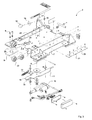
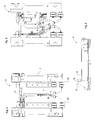
- the base unit is described below in greater detail with reference to Figures 2-6.
- the base unit 2 comprises a casing 4 of relatively strong folded steel plate.
- the casing 4 comprises an upper wall 5 and side walls 6 to which base plates 7 are attached.
- the base unit also comprises four mounting plates 8 that have bolt holes for rigid fixing of the mounting plates to a floor of a vehicle. In the mounted position, the base unit 2 is fixed to the mounting plates 8 by fixing bolts 9. Adjustment of the position of the base unit 2 in the longitudinal direction is made possible by the base plates having a number of fixing holes 10 arranged in a row in the longitudinal direction.
- a locking mechanism is included and fixed in the casing.
- the locking mechanism comprises a hook device 11 that can rotate around a vertical axis A, which hook device has a hook 12 for engaging with the engaging device 3 on the wheelchair.
- the hook device 11 is self-locking and has a spring 13 that urges the hook device towards its locked position.
- the tip 14 of the hook is angled in order to enable the engaging device 3 to rotate the hook device 11 from its locked position assumed by the spring 13, when it is inserted temporarily into the base unit, so that it can thereafter engage with the hook 12.
- the shape of the hook 12 is, however, designed to prevent the engaging device 3 being pushed out of its engagement with the hook.
- an electrically-operated actuator 15 is connected to the hook device 11.
- the base unit 2 also comprises a mechanism (not shown) for manually releasing the engagement between the engaging device and the hook, for example in the event of a loss of power.
- the shape of the hook 12 is, in addition, such that, when it is in engagement with the engaging device 3, it is a close fit around the engaging device 3 in order to prevent relative movement in the horizontal plane between the hook and the engaging device.
- a butt fixing of the wheelchair is thus achieved in directions that are parallel to the floor of the vehicle.
- two buffers 16 are fixed to brackets 17 projecting from the casing, above the base plates 7. In the locked position, the buffers 16 are in contact with the chassis of the wheelchair.
- the buffers 16 are fixed to the brackets 17 with intermediate replaceable spacers 18. By selecting spacers 18 of a thickness to suit the chassis, the position of the buffers 16 can be adjusted so that the wheelchair's engaging device 3 is in the correct position in the longitudinal direction for engagement with the hook 12, when the chassis is in contact with the buffers 16.
- the base unit 2 also comprises two first support surfaces 20 facing away from the floor of the vehicle.
- these first support surfaces 20 are arranged on facing plates 21 that are screwed onto the top side of the upper wall 5.
- the facing plates 21 consist of a hard-wearing material, for example a polymer material.
- the facing plates 21 are replaceable, in order to provide a simple way of avoiding having to use a damaged support surface 20.
- the first support surfaces 20 are arranged to be in contact with corresponding first support surfaces that are arranged on the chassis of the wheelchair. In the example described here, these corresponding first support surfaces are arranged on link arms (not shown) comprised in the chassis.
- the first support surfaces of the base units are arranged at a height above the floor of the vehicle that is somewhat greater than the height above the floor of the corresponding first support surfaces arranged on the chassis.
- the chassis For the docking, the chassis must thus be raised slightly to enable the first support surfaces of the chassis to make contact with the first support surfaces 20 of the base unit 2.
- lifting devices are arranged on the base unit 2. These lifting devices comprise a first set of rollers 22.
- the first support surfaces of the wheelchair come into contact with the rollers 22 slightly below the first support surfaces 20 of the base unit and the highest point of the rollers 22.
- the first support surfaces of the wheelchair roll up on the rollers 22, with the result that the first support surfaces of the wheelchair are on a level with or slightly above the first support surfaces 20 of the base unit.
- the wheelchair can thereafter be moved still further forward, whereby the first support surfaces of the wheelchair come into contact with the first support surfaces 20 of the base unit.
- the engaging device 3 has engaged with the hook 12 and the chassis has come into contact with the buffers 16, the wheelchair has assumed the correct secured docking position.
- the wheelchair's suspension is unloaded and, in this position, at least a part of the weight of the wheelchair is supported by the base unit.
- the wheelchair is prevented from moving downwards towards the floor of the vehicle or from tipping forward, even if very strong downward forces should arise between the first support surfaces of the base unit and the interacting first support surfaces of the wheelchair, for example in the event of a collision while the vehicle is being driven forward.
- the upper wall 4 of the base unit 2 has, in addition, a longitudinal slot or opening 25.
- the slot 25 is open in the backward direction to enable the engaging device to be inserted into the slot when the wheelchair is moved forward in order to cause the engaging device 3 to engage with the hook 12.
- a second support surface 26 on the base unit (see Figure 5) is arranged around the slot 25 on the underside of the upper wall 4.
- this second support surface 26 consists of the downward-facing side of the upper wall 4, around the slot 25.
- This second support surface 26 forms a contact surface that prevents the engaging device 3 from moving vertically upwards when it is in engagement with the hook 12.
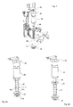
- the engaging device 3 comprises an upper flange 27 at its engaging end (see for example Figure 8a).
- the engaging device 3 comprises a piston 28 that moves in an axial direction, to which the upper flange 27 is rigidly fixed.
- the upper flange has, in addition, an upward-facing second support surface 27a.
- this second support surface 27a is in contact with the second support surface 26 of the base unit 2.
- the piston 28 of the engaging device 3 has a contact flange 29 on its end facing away from the engaging end (see Figure 9b), which contact flange 29 meets with a contact sleeve 30 that is fixed in relation to the wheelchair.
- the contact flange 29 is in contact with the contact sleeve 30 and prevents further withdrawal of the engaging device.
- the contact between the second support surface 27a of the engaging device 3 and the second support surface 26 of the base unit thus also prevents the wheelchair from moving in an upward direction in relation to the base unit 2.
- the engaging device 3 comprises a piston 20 that moves in an axial direction.
- a cylindrical, vertical tube 31 that forms a reinforcement of the chassis of the wheelchair is fixed to the chassis in such a way that it does not move, for example by welding.
- the contact sleeve 30 is arranged in the tube 31 and is fixed rigidly in this, in the vicinity of the lower end of the tube 31.
- the contact sleeve 30 has a central cylindrical opening.
- the opening comprises an upper part 30a with a larger diameter and a lower concentric part 30b with a smaller diameter.
- the diameter of the lower part corresponds essentially to the diameter of the piston 28.
- the upper end of the piston 28 and the contact flange 29, that is fixed to this end by a screw, are arranged in the tube above the contact sleeve 30.
- a spiral spring 32 that urges the contact flange 29 in an upward direction is arranged around the piston and meets with a contact surface that is created in the contact sleeve 30 at the transition between the upper part 30a and lower part 30b of the opening.
- An electrical operating device in the form of a solenoid 33 is arranged in the upper part of the tube 31.
- the solenoid 33 has a projecting flange 34 that meets with an upper ring-shaped end surface of the tube 31 and prevents the solenoid 33 from being moved axially in a downward direction.
- a stop plate 35 that is bolted onto the chassis in the vicinity of the upper end of the tube 31, is in contact with the top side of the solenoid 33 and prevents axial movement of the solenoid 33 in an upward direction.
- the solenoid 33 also has a shaft 36 that moves in an axial direction and projects when the solenoid 33 is activated electrically. The free end of the shaft 36 is in contact with the contact flange 29 that is attached to the piston 28 by a screw.
- the solenoid 33 In the non-activated position shown in Figure 9a, the solenoid 33 is not energized, with the result that the spring 32 urges the piston in an upward direction. The upper flange 27 of the engaging device thereby comes into contact with the lower ring-shaped end surface of the tube 31.
- the solenoid 33 When docking is to be carried out, the solenoid 33 is activated electrically, whereupon the shaft 36 projects and, by overcoming the spring force of the spring 32, pushes the piston in an outward direction, until the contact flange 29 meets with the upper end of the contact sleeve 30.
- the piston 28, and hence the engaging device 3 with the flange 27, have hereby assumed their projecting active positions and, as a result, by moving the wheelchair forward, the engaging device can be inserted into the slot 25 in the base unit 2 and can engage with the hook 12, whereupon the second support surface 27a of the flange 27 also comes into contact with the corresponding second support surface 26 of the base unit around the slot 25.
- the electrical control equipment of the solenoid 33 is suitably arranged so that the solenoid 33 is kept energized for about 20 seconds from when it is activated by, for example, pressing an activating button that can be arranged on the armrest of the wheelchair.
- the engaging device is thereby held in its active position long enough to achieve the docking.
- the solenoid with its relatively high power consumption, does not need to be active for longer than necessary. If the docking is completed within 20 seconds, the solenoid can change to passive mode, with the engaging device being held in its projecting active position by the contact between the two sets of second support surfaces 26 and 27a. If, for some reason, the engaging device does not engage with the hook during the docking, detectors are suitably arranged on the base unit to detect that correct docking has not been achieved and to make the user aware of this in a suitable way.
Landscapes
- Health & Medical Sciences (AREA)
- Public Health (AREA)
- Life Sciences & Earth Sciences (AREA)
- Animal Behavior & Ethology (AREA)
- General Health & Medical Sciences (AREA)
- Veterinary Medicine (AREA)
- Fittings On The Vehicle Exterior For Carrying Loads, And Devices For Holding Or Mounting Articles (AREA)
- Vehicle Body Suspensions (AREA)
- Automatic Cycles, And Cycles In General (AREA)
Applications Claiming Priority (1)
| Application Number | Priority Date | Filing Date | Title |
|---|---|---|---|
| SE0502266A SE528662C2 (sv) | 2005-10-13 | 2005-10-13 | Basenhet och system för dockning och fastlåsning av en rullstol i ett fordon |
Publications (3)
| Publication Number | Publication Date |
|---|---|
| EP1774941A2 true EP1774941A2 (fr) | 2007-04-18 |
| EP1774941A3 EP1774941A3 (fr) | 2007-08-22 |
| EP1774941B1 EP1774941B1 (fr) | 2011-08-17 |
Family
ID=37635598
Family Applications (1)
| Application Number | Title | Priority Date | Filing Date |
|---|---|---|---|
| EP06445066A Not-in-force EP1774941B1 (fr) | 2005-10-13 | 2006-10-05 | Embase et système pour recevoir et sécuriser un fauteuil roulant dans un véhicule |
Country Status (5)
| Country | Link |
|---|---|
| US (1) | US7753630B2 (fr) |
| EP (1) | EP1774941B1 (fr) |
| AT (1) | ATE520383T1 (fr) |
| DK (1) | DK1774941T3 (fr) |
| SE (1) | SE528662C2 (fr) |
Families Citing this family (10)
| Publication number | Priority date | Publication date | Assignee | Title |
|---|---|---|---|---|
| US8308406B2 (en) * | 2009-01-06 | 2012-11-13 | Fall Less Designs & Equipment, Inc. | Wheelchair stabilizing device |
| US20100307850A1 (en) * | 2009-06-09 | 2010-12-09 | Charlie Allen | Wheelchair Drive Base Platform |
| US8650735B2 (en) | 2010-12-22 | 2014-02-18 | Transfer Solutions, Llc | Wheelchair docking system |
| KR101396908B1 (ko) * | 2012-12-05 | 2014-05-19 | 세풍전자공업주식회사 | 차량용 전동휠체어 고정장치 |
| NL2013527B1 (nl) * | 2014-09-26 | 2016-09-29 | Carbouw B V | Zekeringssysteem voor rolstoelen in voertuigen, en een werkwijze voor het ontgrendelen respectievelijk vergrendelen van een zekeringssysteem voor rolstoelen in voertuigen. |
| US10058464B2 (en) | 2015-10-23 | 2018-08-28 | Stryker Corporation | Cot fastening system |
| US9839565B1 (en) * | 2016-04-22 | 2017-12-12 | Gary M Harris | Anti-tip lateral transfer system |
| DK179512B1 (en) * | 2017-04-04 | 2019-02-04 | Maskinfabrik Dahl Engineering V/Claus Dahl Pedersen | Height adjustable wheelchair docking system |
| CA3168572C (fr) | 2022-07-13 | 2025-08-05 | Invacare Corporation | Fauteuil roulant et systemes de suspension |
| US11883337B1 (en) * | 2022-08-23 | 2024-01-30 | B.A.K Technology Ltd | Systems and methods for modularly loading different driver seats including wheelchairs onto an off-road vehicle and an off-road vehicle including same |
Family Cites Families (5)
| Publication number | Priority date | Publication date | Assignee | Title |
|---|---|---|---|---|
| US4541134A (en) | 1982-09-04 | 1985-09-17 | The University Of Bath | Vibration damping supports |
| US4690364A (en) * | 1986-04-14 | 1987-09-01 | Constantin Bruce J | Wheelchair restraining device |
| US4973022A (en) * | 1989-06-16 | 1990-11-27 | Action Concepts, Inc. | Wheelchair securement apparatus |
| US5466111A (en) * | 1995-03-03 | 1995-11-14 | Meyer; Rudolf X. | Wheelchair and lifting apparatus for handicapped persons driving automobiles |
| US6231283B1 (en) * | 1997-09-15 | 2001-05-15 | Thomas R. Stowers | Vehicle restraint apparatus |
-
2005
- 2005-10-13 SE SE0502266A patent/SE528662C2/sv not_active IP Right Cessation
-
2006
- 2006-10-04 US US11/538,742 patent/US7753630B2/en not_active Expired - Fee Related
- 2006-10-05 DK DK06445066.1T patent/DK1774941T3/da active
- 2006-10-05 EP EP06445066A patent/EP1774941B1/fr not_active Not-in-force
- 2006-10-05 AT AT06445066T patent/ATE520383T1/de not_active IP Right Cessation
Non-Patent Citations (1)
| Title |
|---|
| None |
Also Published As
| Publication number | Publication date |
|---|---|
| US20070154275A1 (en) | 2007-07-05 |
| DK1774941T3 (da) | 2011-12-05 |
| EP1774941B1 (fr) | 2011-08-17 |
| EP1774941A3 (fr) | 2007-08-22 |
| US7753630B2 (en) | 2010-07-13 |
| SE0502266L (sv) | 2007-01-16 |
| ATE520383T1 (de) | 2011-09-15 |
| SE528662C2 (sv) | 2007-01-16 |
Similar Documents
| Publication | Publication Date | Title |
|---|---|---|
| US8226163B1 (en) | Aircraft divan | |
| US8398356B2 (en) | Automotive wheelchair mobility system | |
| EP0921962B1 (fr) | Siege de vehicule | |
| EP1774941B1 (fr) | Embase et système pour recevoir et sécuriser un fauteuil roulant dans un véhicule | |
| US8220833B2 (en) | Rotational breakaway trailer jack assembly and method of use | |
| US9994130B2 (en) | Transfer seat with locking mechanism | |
| AU2005259881B2 (en) | Combination cot loading and fastening system | |
| US6942263B2 (en) | Mount for truck mounted attenuator | |
| US7854437B2 (en) | Vehicle conversion assembly and method of converting a vehicle | |
| EP3877222B1 (fr) | Unité de manipulation de cale de roue | |
| US20110280700A1 (en) | Transfer device | |
| US7654602B2 (en) | Reclining seat for a material handling vehicle | |
| US12447934B2 (en) | Universal joint for a wheel chock | |
| US20040262055A1 (en) | Adjustable wheelchair | |
| US7918501B1 (en) | Vehicle safety seat | |
| AU2021282423A1 (en) | Child restraint system | |
| US8162335B1 (en) | Raised axle and suspension system | |
| CN120396934A (zh) | 防侧翻方法、防侧翻结构、防侧翻系统和车辆 | |
| EP3122592B1 (fr) | Mécanisme de commande d'inclinaison de siège | |
| US8579349B1 (en) | Headrest assembly | |
| US6540294B2 (en) | Stowable swing away flip seat | |
| WO2008073026A1 (fr) | Agencement de lit pour véhicules | |
| US20080056872A1 (en) | Vehicle Passenger Lift | |
| CN209240931U (zh) | 汽车安全座椅及汽车座椅系统 | |
| AU766829B2 (en) | Vehicle seat and stand for vehicle seat |
Legal Events
| Date | Code | Title | Description |
|---|---|---|---|
| PUAI | Public reference made under article 153(3) epc to a published international application that has entered the european phase |
Free format text: ORIGINAL CODE: 0009012 |
|
| AK | Designated contracting states |
Kind code of ref document: A2 Designated state(s): AT BE BG CH CY CZ DE DK EE ES FI FR GB GR HU IE IS IT LI LT LU LV MC NL PL PT RO SE SI SK TR |
|
| AX | Request for extension of the european patent |
Extension state: AL BA HR MK YU |
|
| PUAL | Search report despatched |
Free format text: ORIGINAL CODE: 0009013 |
|
| AK | Designated contracting states |
Kind code of ref document: A3 Designated state(s): AT BE BG CH CY CZ DE DK EE ES FI FR GB GR HU IE IS IT LI LT LU LV MC NL PL PT RO SE SI SK TR |
|
| AX | Request for extension of the european patent |
Extension state: AL BA HR MK YU |
|
| 17P | Request for examination filed |
Effective date: 20080220 |
|
| 17Q | First examination report despatched |
Effective date: 20080327 |
|
| AKX | Designation fees paid |
Designated state(s): AT BE BG CH CY CZ DE DK EE ES FI FR GB GR HU IE IS IT LI LT LU LV MC NL PL PT RO SE SI SK TR |
|
| GRAP | Despatch of communication of intention to grant a patent |
Free format text: ORIGINAL CODE: EPIDOSNIGR1 |
|
| GRAS | Grant fee paid |
Free format text: ORIGINAL CODE: EPIDOSNIGR3 |
|
| GRAA | (expected) grant |
Free format text: ORIGINAL CODE: 0009210 |
|
| AK | Designated contracting states |
Kind code of ref document: B1 Designated state(s): AT BE BG CH CY CZ DE DK EE ES FI FR GB GR HU IE IS IT LI LT LU LV MC NL PL PT RO SE SI SK TR |
|
| REG | Reference to a national code |
Ref country code: GB Ref legal event code: FG4D |
|
| REG | Reference to a national code |
Ref country code: CH Ref legal event code: EP |
|
| REG | Reference to a national code |
Ref country code: IE Ref legal event code: FG4D |
|
| REG | Reference to a national code |
Ref country code: DE Ref legal event code: R096 Ref document number: 602006023816 Country of ref document: DE Effective date: 20111020 |
|
| REG | Reference to a national code |
Ref country code: NL Ref legal event code: T3 |
|
| REG | Reference to a national code |
Ref country code: DK Ref legal event code: T3 |
|
| REG | Reference to a national code |
Ref country code: SE Ref legal event code: TRGR |
|
| LTIE | Lt: invalidation of european patent or patent extension |
Effective date: 20110817 |
|
| PG25 | Lapsed in a contracting state [announced via postgrant information from national office to epo] |
Ref country code: LT Free format text: LAPSE BECAUSE OF FAILURE TO SUBMIT A TRANSLATION OF THE DESCRIPTION OR TO PAY THE FEE WITHIN THE PRESCRIBED TIME-LIMIT Effective date: 20110817 Ref country code: FI Free format text: LAPSE BECAUSE OF FAILURE TO SUBMIT A TRANSLATION OF THE DESCRIPTION OR TO PAY THE FEE WITHIN THE PRESCRIBED TIME-LIMIT Effective date: 20110817 Ref country code: IS Free format text: LAPSE BECAUSE OF FAILURE TO SUBMIT A TRANSLATION OF THE DESCRIPTION OR TO PAY THE FEE WITHIN THE PRESCRIBED TIME-LIMIT Effective date: 20111217 Ref country code: PT Free format text: LAPSE BECAUSE OF FAILURE TO SUBMIT A TRANSLATION OF THE DESCRIPTION OR TO PAY THE FEE WITHIN THE PRESCRIBED TIME-LIMIT Effective date: 20111219 |
|
| REG | Reference to a national code |
Ref country code: AT Ref legal event code: MK05 Ref document number: 520383 Country of ref document: AT Kind code of ref document: T Effective date: 20110817 |
|
| PG25 | Lapsed in a contracting state [announced via postgrant information from national office to epo] |
Ref country code: CY Free format text: LAPSE BECAUSE OF FAILURE TO SUBMIT A TRANSLATION OF THE DESCRIPTION OR TO PAY THE FEE WITHIN THE PRESCRIBED TIME-LIMIT Effective date: 20110817 Ref country code: LV Free format text: LAPSE BECAUSE OF FAILURE TO SUBMIT A TRANSLATION OF THE DESCRIPTION OR TO PAY THE FEE WITHIN THE PRESCRIBED TIME-LIMIT Effective date: 20110817 Ref country code: PL Free format text: LAPSE BECAUSE OF FAILURE TO SUBMIT A TRANSLATION OF THE DESCRIPTION OR TO PAY THE FEE WITHIN THE PRESCRIBED TIME-LIMIT Effective date: 20110817 Ref country code: SI Free format text: LAPSE BECAUSE OF FAILURE TO SUBMIT A TRANSLATION OF THE DESCRIPTION OR TO PAY THE FEE WITHIN THE PRESCRIBED TIME-LIMIT Effective date: 20110817 Ref country code: AT Free format text: LAPSE BECAUSE OF FAILURE TO SUBMIT A TRANSLATION OF THE DESCRIPTION OR TO PAY THE FEE WITHIN THE PRESCRIBED TIME-LIMIT Effective date: 20110817 Ref country code: GR Free format text: LAPSE BECAUSE OF FAILURE TO SUBMIT A TRANSLATION OF THE DESCRIPTION OR TO PAY THE FEE WITHIN THE PRESCRIBED TIME-LIMIT Effective date: 20111118 |
|
| PG25 | Lapsed in a contracting state [announced via postgrant information from national office to epo] |
Ref country code: SK Free format text: LAPSE BECAUSE OF FAILURE TO SUBMIT A TRANSLATION OF THE DESCRIPTION OR TO PAY THE FEE WITHIN THE PRESCRIBED TIME-LIMIT Effective date: 20110817 Ref country code: CZ Free format text: LAPSE BECAUSE OF FAILURE TO SUBMIT A TRANSLATION OF THE DESCRIPTION OR TO PAY THE FEE WITHIN THE PRESCRIBED TIME-LIMIT Effective date: 20110817 |
|
| PG25 | Lapsed in a contracting state [announced via postgrant information from national office to epo] |
Ref country code: IT Free format text: LAPSE BECAUSE OF FAILURE TO SUBMIT A TRANSLATION OF THE DESCRIPTION OR TO PAY THE FEE WITHIN THE PRESCRIBED TIME-LIMIT Effective date: 20110817 Ref country code: RO Free format text: LAPSE BECAUSE OF FAILURE TO SUBMIT A TRANSLATION OF THE DESCRIPTION OR TO PAY THE FEE WITHIN THE PRESCRIBED TIME-LIMIT Effective date: 20110817 Ref country code: MC Free format text: LAPSE BECAUSE OF NON-PAYMENT OF DUE FEES Effective date: 20111031 Ref country code: EE Free format text: LAPSE BECAUSE OF FAILURE TO SUBMIT A TRANSLATION OF THE DESCRIPTION OR TO PAY THE FEE WITHIN THE PRESCRIBED TIME-LIMIT Effective date: 20110817 |
|
| REG | Reference to a national code |
Ref country code: CH Ref legal event code: PL |
|
| PLBE | No opposition filed within time limit |
Free format text: ORIGINAL CODE: 0009261 |
|
| STAA | Information on the status of an ep patent application or granted ep patent |
Free format text: STATUS: NO OPPOSITION FILED WITHIN TIME LIMIT |
|
| 26N | No opposition filed |
Effective date: 20120521 |
|
| PG25 | Lapsed in a contracting state [announced via postgrant information from national office to epo] |
Ref country code: LI Free format text: LAPSE BECAUSE OF NON-PAYMENT OF DUE FEES Effective date: 20111031 Ref country code: CH Free format text: LAPSE BECAUSE OF NON-PAYMENT OF DUE FEES Effective date: 20111031 |
|
| REG | Reference to a national code |
Ref country code: IE Ref legal event code: MM4A |
|
| REG | Reference to a national code |
Ref country code: DE Ref legal event code: R097 Ref document number: 602006023816 Country of ref document: DE Effective date: 20120521 |
|
| PG25 | Lapsed in a contracting state [announced via postgrant information from national office to epo] |
Ref country code: IE Free format text: LAPSE BECAUSE OF NON-PAYMENT OF DUE FEES Effective date: 20111005 |
|
| PG25 | Lapsed in a contracting state [announced via postgrant information from national office to epo] |
Ref country code: ES Free format text: LAPSE BECAUSE OF FAILURE TO SUBMIT A TRANSLATION OF THE DESCRIPTION OR TO PAY THE FEE WITHIN THE PRESCRIBED TIME-LIMIT Effective date: 20111128 |
|
| PG25 | Lapsed in a contracting state [announced via postgrant information from national office to epo] |
Ref country code: LU Free format text: LAPSE BECAUSE OF NON-PAYMENT OF DUE FEES Effective date: 20111005 |
|
| PG25 | Lapsed in a contracting state [announced via postgrant information from national office to epo] |
Ref country code: BG Free format text: LAPSE BECAUSE OF FAILURE TO SUBMIT A TRANSLATION OF THE DESCRIPTION OR TO PAY THE FEE WITHIN THE PRESCRIBED TIME-LIMIT Effective date: 20111117 |
|
| PG25 | Lapsed in a contracting state [announced via postgrant information from national office to epo] |
Ref country code: TR Free format text: LAPSE BECAUSE OF FAILURE TO SUBMIT A TRANSLATION OF THE DESCRIPTION OR TO PAY THE FEE WITHIN THE PRESCRIBED TIME-LIMIT Effective date: 20110817 |
|
| PG25 | Lapsed in a contracting state [announced via postgrant information from national office to epo] |
Ref country code: HU Free format text: LAPSE BECAUSE OF FAILURE TO SUBMIT A TRANSLATION OF THE DESCRIPTION OR TO PAY THE FEE WITHIN THE PRESCRIBED TIME-LIMIT Effective date: 20110817 |
|
| REG | Reference to a national code |
Ref country code: FR Ref legal event code: PLFP Year of fee payment: 10 |
|
| REG | Reference to a national code |
Ref country code: FR Ref legal event code: PLFP Year of fee payment: 11 |
|
| PGFP | Annual fee paid to national office [announced via postgrant information from national office to epo] |
Ref country code: DE Payment date: 20161021 Year of fee payment: 11 Ref country code: FR Payment date: 20161014 Year of fee payment: 11 Ref country code: NL Payment date: 20161018 Year of fee payment: 11 Ref country code: DK Payment date: 20161026 Year of fee payment: 11 Ref country code: GB Payment date: 20161024 Year of fee payment: 11 |
|
| PGFP | Annual fee paid to national office [announced via postgrant information from national office to epo] |
Ref country code: SE Payment date: 20161024 Year of fee payment: 11 Ref country code: BE Payment date: 20161018 Year of fee payment: 11 |
|
| REG | Reference to a national code |
Ref country code: DE Ref legal event code: R119 Ref document number: 602006023816 Country of ref document: DE |
|
| REG | Reference to a national code |
Ref country code: DK Ref legal event code: EBP Effective date: 20171031 |
|
| REG | Reference to a national code |
Ref country code: SE Ref legal event code: EUG |
|
| REG | Reference to a national code |
Ref country code: NL Ref legal event code: MM Effective date: 20171101 |
|
| GBPC | Gb: european patent ceased through non-payment of renewal fee |
Effective date: 20171005 |
|
| REG | Reference to a national code |
Ref country code: FR Ref legal event code: ST Effective date: 20180629 |
|
| PG25 | Lapsed in a contracting state [announced via postgrant information from national office to epo] |
Ref country code: DE Free format text: LAPSE BECAUSE OF NON-PAYMENT OF DUE FEES Effective date: 20180501 Ref country code: NL Free format text: LAPSE BECAUSE OF NON-PAYMENT OF DUE FEES Effective date: 20171101 Ref country code: GB Free format text: LAPSE BECAUSE OF NON-PAYMENT OF DUE FEES Effective date: 20171005 |
|
| REG | Reference to a national code |
Ref country code: BE Ref legal event code: MM Effective date: 20171031 |
|
| PG25 | Lapsed in a contracting state [announced via postgrant information from national office to epo] |
Ref country code: FR Free format text: LAPSE BECAUSE OF NON-PAYMENT OF DUE FEES Effective date: 20171031 Ref country code: SE Free format text: LAPSE BECAUSE OF NON-PAYMENT OF DUE FEES Effective date: 20171006 Ref country code: BE Free format text: LAPSE BECAUSE OF NON-PAYMENT OF DUE FEES Effective date: 20171031 |
|
| PG25 | Lapsed in a contracting state [announced via postgrant information from national office to epo] |
Ref country code: DK Free format text: LAPSE BECAUSE OF NON-PAYMENT OF DUE FEES Effective date: 20171031 |