EP1775108A1 - Tete multi-applicateur de bandes de fibre et procede d'application des bandes de fibre - Google Patents
Tete multi-applicateur de bandes de fibre et procede d'application des bandes de fibre Download PDFInfo
- Publication number
- EP1775108A1 EP1775108A1 EP05783690A EP05783690A EP1775108A1 EP 1775108 A1 EP1775108 A1 EP 1775108A1 EP 05783690 A EP05783690 A EP 05783690A EP 05783690 A EP05783690 A EP 05783690A EP 1775108 A1 EP1775108 A1 EP 1775108A1
- Authority
- EP
- European Patent Office
- Prior art keywords
- strips
- tape
- roller
- head
- fiber
- Prior art date
- Legal status (The legal status is an assumption and is not a legal conclusion. Google has not performed a legal analysis and makes no representation as to the accuracy of the status listed.)
- Granted
Links
Images




Classifications
-
- B—PERFORMING OPERATIONS; TRANSPORTING
- B29—WORKING OF PLASTICS; WORKING OF SUBSTANCES IN A PLASTIC STATE IN GENERAL
- B29C—SHAPING OR JOINING OF PLASTICS; SHAPING OF MATERIAL IN A PLASTIC STATE, NOT OTHERWISE PROVIDED FOR; AFTER-TREATMENT OF THE SHAPED PRODUCTS, e.g. REPAIRING
- B29C70/00—Shaping composites, i.e. plastics material comprising reinforcements, fillers or preformed parts, e.g. inserts
- B29C70/04—Shaping composites, i.e. plastics material comprising reinforcements, fillers or preformed parts, e.g. inserts comprising reinforcements only, e.g. self-reinforcing plastics
- B29C70/28—Shaping operations therefor
- B29C70/54—Component parts, details or accessories; Auxiliary operations, e.g. feeding or storage of prepregs or SMC after impregnation or during ageing
- B29C70/545—Perforating, cutting or machining during or after moulding
-
- B—PERFORMING OPERATIONS; TRANSPORTING
- B29—WORKING OF PLASTICS; WORKING OF SUBSTANCES IN A PLASTIC STATE IN GENERAL
- B29C—SHAPING OR JOINING OF PLASTICS; SHAPING OF MATERIAL IN A PLASTIC STATE, NOT OTHERWISE PROVIDED FOR; AFTER-TREATMENT OF THE SHAPED PRODUCTS, e.g. REPAIRING
- B29C70/00—Shaping composites, i.e. plastics material comprising reinforcements, fillers or preformed parts, e.g. inserts
- B29C70/04—Shaping composites, i.e. plastics material comprising reinforcements, fillers or preformed parts, e.g. inserts comprising reinforcements only, e.g. self-reinforcing plastics
- B29C70/28—Shaping operations therefor
- B29C70/30—Shaping by lay-up, i.e. applying fibres, tape or broadsheet on a mould, former or core; Shaping by spray-up, i.e. spraying of fibres on a mould, former or core
- B29C70/38—Automated lay-up, e.g. using robots, laying filaments according to predetermined patterns
-
- B—PERFORMING OPERATIONS; TRANSPORTING
- B29—WORKING OF PLASTICS; WORKING OF SUBSTANCES IN A PLASTIC STATE IN GENERAL
- B29C—SHAPING OR JOINING OF PLASTICS; SHAPING OF MATERIAL IN A PLASTIC STATE, NOT OTHERWISE PROVIDED FOR; AFTER-TREATMENT OF THE SHAPED PRODUCTS, e.g. REPAIRING
- B29C70/00—Shaping composites, i.e. plastics material comprising reinforcements, fillers or preformed parts, e.g. inserts
- B29C70/04—Shaping composites, i.e. plastics material comprising reinforcements, fillers or preformed parts, e.g. inserts comprising reinforcements only, e.g. self-reinforcing plastics
- B29C70/28—Shaping operations therefor
- B29C70/30—Shaping by lay-up, i.e. applying fibres, tape or broadsheet on a mould, former or core; Shaping by spray-up, i.e. spraying of fibres on a mould, former or core
- B29C70/32—Shaping by lay-up, i.e. applying fibres, tape or broadsheet on a mould, former or core; Shaping by spray-up, i.e. spraying of fibres on a mould, former or core on a rotating mould, former or core
-
- B—PERFORMING OPERATIONS; TRANSPORTING
- B29—WORKING OF PLASTICS; WORKING OF SUBSTANCES IN A PLASTIC STATE IN GENERAL
- B29C—SHAPING OR JOINING OF PLASTICS; SHAPING OF MATERIAL IN A PLASTIC STATE, NOT OTHERWISE PROVIDED FOR; AFTER-TREATMENT OF THE SHAPED PRODUCTS, e.g. REPAIRING
- B29C70/00—Shaping composites, i.e. plastics material comprising reinforcements, fillers or preformed parts, e.g. inserts
- B29C70/04—Shaping composites, i.e. plastics material comprising reinforcements, fillers or preformed parts, e.g. inserts comprising reinforcements only, e.g. self-reinforcing plastics
- B29C70/28—Shaping operations therefor
- B29C70/30—Shaping by lay-up, i.e. applying fibres, tape or broadsheet on a mould, former or core; Shaping by spray-up, i.e. spraying of fibres on a mould, former or core
- B29C70/38—Automated lay-up, e.g. using robots, laying filaments according to predetermined patterns
- B29C70/386—Automated tape laying [ATL]
- B29C70/388—Tape placement heads, e.g. component parts, details or accessories
-
- Y—GENERAL TAGGING OF NEW TECHNOLOGICAL DEVELOPMENTS; GENERAL TAGGING OF CROSS-SECTIONAL TECHNOLOGIES SPANNING OVER SEVERAL SECTIONS OF THE IPC; TECHNICAL SUBJECTS COVERED BY FORMER USPC CROSS-REFERENCE ART COLLECTIONS [XRACs] AND DIGESTS
- Y10—TECHNICAL SUBJECTS COVERED BY FORMER USPC
- Y10T—TECHNICAL SUBJECTS COVERED BY FORMER US CLASSIFICATION
- Y10T156/00—Adhesive bonding and miscellaneous chemical manufacture
- Y10T156/10—Methods of surface bonding and/or assembly therefor
- Y10T156/1052—Methods of surface bonding and/or assembly therefor with cutting, punching, tearing or severing
- Y10T156/1056—Perforating lamina
-
- Y—GENERAL TAGGING OF NEW TECHNOLOGICAL DEVELOPMENTS; GENERAL TAGGING OF CROSS-SECTIONAL TECHNOLOGIES SPANNING OVER SEVERAL SECTIONS OF THE IPC; TECHNICAL SUBJECTS COVERED BY FORMER USPC CROSS-REFERENCE ART COLLECTIONS [XRACs] AND DIGESTS
- Y10—TECHNICAL SUBJECTS COVERED BY FORMER USPC
- Y10T—TECHNICAL SUBJECTS COVERED BY FORMER US CLASSIFICATION
- Y10T156/00—Adhesive bonding and miscellaneous chemical manufacture
- Y10T156/10—Methods of surface bonding and/or assembly therefor
- Y10T156/1052—Methods of surface bonding and/or assembly therefor with cutting, punching, tearing or severing
- Y10T156/1062—Prior to assembly
-
- Y—GENERAL TAGGING OF NEW TECHNOLOGICAL DEVELOPMENTS; GENERAL TAGGING OF CROSS-SECTIONAL TECHNOLOGIES SPANNING OVER SEVERAL SECTIONS OF THE IPC; TECHNICAL SUBJECTS COVERED BY FORMER USPC CROSS-REFERENCE ART COLLECTIONS [XRACs] AND DIGESTS
- Y10—TECHNICAL SUBJECTS COVERED BY FORMER USPC
- Y10T—TECHNICAL SUBJECTS COVERED BY FORMER US CLASSIFICATION
- Y10T156/00—Adhesive bonding and miscellaneous chemical manufacture
- Y10T156/12—Surface bonding means and/or assembly means with cutting, punching, piercing, severing or tearing
-
- Y—GENERAL TAGGING OF NEW TECHNOLOGICAL DEVELOPMENTS; GENERAL TAGGING OF CROSS-SECTIONAL TECHNOLOGIES SPANNING OVER SEVERAL SECTIONS OF THE IPC; TECHNICAL SUBJECTS COVERED BY FORMER USPC CROSS-REFERENCE ART COLLECTIONS [XRACs] AND DIGESTS
- Y10—TECHNICAL SUBJECTS COVERED BY FORMER USPC
- Y10T—TECHNICAL SUBJECTS COVERED BY FORMER US CLASSIFICATION
- Y10T156/00—Adhesive bonding and miscellaneous chemical manufacture
- Y10T156/12—Surface bonding means and/or assembly means with cutting, punching, piercing, severing or tearing
- Y10T156/125—Plural severing means each acting on a different work piece
-
- Y—GENERAL TAGGING OF NEW TECHNOLOGICAL DEVELOPMENTS; GENERAL TAGGING OF CROSS-SECTIONAL TECHNOLOGIES SPANNING OVER SEVERAL SECTIONS OF THE IPC; TECHNICAL SUBJECTS COVERED BY FORMER USPC CROSS-REFERENCE ART COLLECTIONS [XRACs] AND DIGESTS
- Y10—TECHNICAL SUBJECTS COVERED BY FORMER USPC
- Y10T—TECHNICAL SUBJECTS COVERED BY FORMER US CLASSIFICATION
- Y10T156/00—Adhesive bonding and miscellaneous chemical manufacture
- Y10T156/12—Surface bonding means and/or assembly means with cutting, punching, piercing, severing or tearing
- Y10T156/1317—Means feeding plural workpieces to be joined
-
- Y—GENERAL TAGGING OF NEW TECHNOLOGICAL DEVELOPMENTS; GENERAL TAGGING OF CROSS-SECTIONAL TECHNOLOGIES SPANNING OVER SEVERAL SECTIONS OF THE IPC; TECHNICAL SUBJECTS COVERED BY FORMER USPC CROSS-REFERENCE ART COLLECTIONS [XRACs] AND DIGESTS
- Y10—TECHNICAL SUBJECTS COVERED BY FORMER USPC
- Y10T—TECHNICAL SUBJECTS COVERED BY FORMER US CLASSIFICATION
- Y10T156/00—Adhesive bonding and miscellaneous chemical manufacture
- Y10T156/12—Surface bonding means and/or assembly means with cutting, punching, piercing, severing or tearing
- Y10T156/1317—Means feeding plural workpieces to be joined
- Y10T156/1322—Severing before bonding or assembling of parts
Definitions
- the present invention relates to the application of carbon fiber strips, glass fiber strips or the like for the formation of laminar parts, proposing a head for said function provided with means optimizing the functional behavior for the mentioned application, as well as a method for carrying out this application.
- Said heads carry out the application of a strip or web of the corresponding material, repeating the application successively in a side progression until the entire width of the surface to be formed is covered, for which the strips or bands which are applied can be wide, for the purpose of covering the entire surface with a minimum number of runs, having the drawback that it is necessary to waste a large amount of material in the cuts for shaping the edges of the laminar parts, especially when said edges are oblique or irregular.
- Strips with a small width can be used instead, whereby the waste material is reduced because the individual adjustment of the length of the used strips allows a better adaptation in the ends with respect to the edges, and therefore the shaping cut required is smaller, but on the other hand, with this solution the number of runs necessary to cover the entire application surface is greater, therefore the work time increase and the efficiency decreases.
- Multiapplicator heads have been developed to solve the problem, such as the one of Spanish Patent ES 200200524 of this same applicant, such that a series of strips with a small width are applied jointly in each run, with which strips as a whole a considerable application width is determined, the contribution of the supplied strips being independent of the others, which allows starting and ending the application of each strip as required, thus being able to make the cuts for shaping the edges of the parts, like the hollows existing therein, by means of the interruption of the corresponding strips when necessary, whereby the process occurs with little waste of material.
- the head of the invention comprises a reel-holder in which multiple spools supplying the fiber strips to be applied are incorporated, which fiber strips are led separately to an application area, where they are projected occupying a joint band between all of them, being compacted by means of a pressure system acting on the strips in said area, whereas before the application area there is a selective strip cutting system incorporated.
- the pressure system on the strips in the application area consists of a roller of flexible material capable of adapting to the surface to be taped, said roller being actuated by two cylinders exerting a floating pressure, thus achieving a perfectly uniform application of the fiber strips.
- the rollers serving as a guiding for the fiber strips are distributed by pairs in respective side assemblies, from which the corresponding strips pass by the sides of a leading body, going in relation to those functional respective side assemblies, each of which incorporates a master roller for dragging the fiber strips and a fiber strip cutting system.
- the mentioned side assemblies can be moved towards the outside independently, thus facilitating the maintenance and cleaning operations, as well as the threading of the fiber strips through the corresponding leading passages towards the application area.
- the body of the head is formed by a structural formation of parallel sheets with intermediate dividers, determining hollow spaces between the component sheets, through which the fiber strips are guided in their supply towards the application area.
- the dividers included between the sheets have holes through which an injection of air acting as lubricant occurs, reducing the friction of the strips in the leading hollows.
- the cutting systems integrated in the side assemblies correspond in an individual operative manner to the path of the different fiber strips towards the application area, allowing to cut each of the strips selectively when it is necessary to interrupt their application.
- end cutting systems provided with blades accompanying the longitudinal movement of the corresponding strips during the cutting action are foreseen, which blades are arranged in rotating supports provided with one or more blades, in correspondence with the respective areas for the passage of the different fiber strips, said blade-carrying supports having a rotating movement synchronized with the movement of the corresponding fibers strips, which allows making the cuts accurately.
- the master rollers of the side assemblies are formed by a pack of rings which are assembled with movement and actuation of individual rotation, such that each of said rings can actuate the pulling for moving one of the fiber strips by trapping it against a dolly roller, the respective cutting systems for the different strips being individually synchronized with those rings by means of gearing or any mechanical, hydraulic, electromagnetic or any other type of method allowing to carry out said function.
- the mentioned rings of the master rollers have in the periphery recesses which allow leaving the fiber strips free when they are facing the dolly roller, such that by means of a computer control of the operation, during the normal supplying process towards the application area the fiber strips are free from the action of the mentioned master rollers and when a cut has to occur, the ring of the corresponding master roller is actuated in an angular rotation, carrying out the trapping and pulling of the strip to be cut at the same time that it makes the corresponding cutting system rotate, whereby a completely accurate cut is obtained, keeping the fiber strip secured while the necessary pulling movement thereof is carried out, which allows carrying out the cutting and restarting processes of the fiber strips in a synchronized manner and without reducing the programmed speed.
- the method for applying the fiber strips with the mentioned head is also the object of the present invention, such that starting from the position in which the tape moves freely forward through the head towards the compacting roller, the master roller is accelerated until reaching the synchronism speed with the forward movement of the tape, at which time the master roller traps the tape according to its larger diameter in this area, and with tape thus trapped by the master roller, the synchronized movement of the cutting mechanism cuts the tape, the deceleration then occurring until the forward movement of the part of the tape trapped by the master roller is stopped.
- the restarting of the tape occurs by accelerating the master roller with the trapped tape, until reaching the speed of the forward movement of the head on the application surface, dispensing tape at said speed until the contact thereof with the compacting element, plus a safety distance for ensuring the correct adherence of the end of the tape to the application surface, after which the master roller releases the tape according to its smaller diameter in the corresponding area in this phase and decelerates until it stops, allowing the tape to move forward freely through the head.
- the object of the invention relates to a head intended for the formation of laminar parts by means of carbon fiber strips, glass fiber strips or other similar ones, which are applied as a multiple group forming application bands, proposing peculiarities in the embodiment of said invention which improve the functionality thereof.
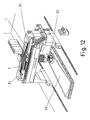
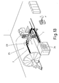
- the head (23) of the invention is arranged in combination with one or more reel-holders (24), in which the spools supplying the fiber strips (1) to be applied are incorporated, which fiber strips are led separately towards the application area (2), where they are supplied jointly forming an application web on the surface (25) of the part to be formed.
- the reels supplying the fiber strips (1) are arranged in pairs in respective side assemblies, the strips (1) being led by the sides of the body (3) of the applicator head, where respective side assemblies are incorporated, which side assemblies are formed by a master roller (4) that can carry out the pulling of the corresponding strips (1) towards the application area (2), and a cutting system (5), by means of which the individual selective cut of the strips (1) can be carried out to interrupt the application thereof in the corresponding parts.
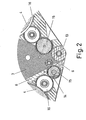
- the body (3) of the head is formed by a structural formation of parallel sheets, including dividers (6) between the component sheets, as shown in figures 2 and 3, such that between said component sheets of the body (3) there are hollow spaces, through which the fiber strips (1) are led separately in the path towards the application area (2).
- the dividers (6) are provided with holes, such that through them, an injection of air acting as lubricant occurs, reducing the friction of the strips in the passage through the leading hollows.
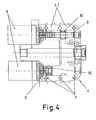
- the master rollers (4) are formed by a set of rollers (4.1) arranged in axial assembly, as shown in figures 4 to 6, said rings (4.1) going separately to one another by means of balls (7), such that the different rings (4.1) are rotationally independent like the parts of a bearing.
- each master roller (4) are actuated independently in a rotating actuation by means of respective motors (8), from which they extend through the inside of the roller (4) with respect to shafts (9) establishing, by means of pinions (10), a gearing with the corresponding rings (4.1) for the individual actuation of the latter.
- each ring (4.1) of the master rollers (4) corresponds to the area for the passage of the fiber strips (1) towards the application area, allowing to actuate, in contrast to the corresponding dolly roller (11), the pulling of the respective strip (1), so as to provide it with the speed required by the process.
- Said rings (4.1) of the master rollers have recesses (12) in the periphery, such that according to the peripheral area facing the dolly roller (11), the corresponding strip (1) is trapped or does not enter the ring (4.1) and the dolly roller (11), allowing to give an acceleration or deceleration to the strip (1) when it is trapped and leaving it free from passage when the areas in which the trapping is not carried out coincide.
- the latter are led to the application area (2) where they are pressed by a pressure system against the surface to be taped, such that in a first feed phase the strips (1) are pulled towards the application area (2) by the corresponding rings (4.1) of the master rollers (4), which give the strips (1) the necessary acceleration for the application speed, later being pulled by the movement itself of the head, thanks to the application pressure, leaving the rings (4.1) free.
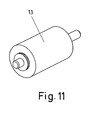
- the pressure system acting on the fiber strips (1) in the application area (2) consists of a roller (13) of flexible material capable of adapting to the surface on which the fiber strips (1) are applied, said roller being actuated by two cylinders exerting a floating pressure, whereby a perfectly uniform application of the fiber strips (1) is achieved.
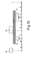
- each side assembly comprises blades (14) that can act in relation to the areas for the passage of the different fiber strips (1) in the leading to the application area (2), which blades (14) are incorporated in corresponding rotating supports (15), according to figures 9 to 11, such that the rotating support (15) of each blade (14) is connected by means of a rotating coupling (16) to a ring (4.1) of the corresponding master roller (4), whereby each blade (14) is in a synchronized actuation relation with the driving actuation of the corresponding ring (4.1) of the respective master roller (4).
- the rotating couplings (16) between the supports (15) of the blades (14) and the rings (4.1) of the corresponding master roller (4) can be of any mechanical, hydraulic, electromagnetic type etc. which allows establishing a synchronization.
- Dolly rollers (14) are arranged in a position facing the position of the blades (14), in the other side of the area for the passage of the corresponding fiber strips (1), against which dolly rollers the blades (14) act while cutting the fiber strips (1), such that during said cutting, the blades (14) accompany the movement for moving the strip (1) on which the cut is made, thus preventing roughness and tugs and therefore a low cutting quality.
- each ring (4.1) has a size that is n-times the size of the support (15) carrying the respective blade (14) of the cutting system (5), such that n start-cut-restart processes can occur with a complete rotation of the ring (4.1).
- Said length of the development of the support (15) of the blade (14) is equivalent to the minimum length of the strip (1) to be cut, in order to make the cut, corresponding to the different areas of the following phases:
Landscapes
- Engineering & Computer Science (AREA)
- Chemical & Material Sciences (AREA)
- Composite Materials (AREA)
- Mechanical Engineering (AREA)
- Robotics (AREA)
- Treatment Of Fiber Materials (AREA)
- Road Repair (AREA)
- Nonwoven Fabrics (AREA)
Applications Claiming Priority (2)
| Application Number | Priority Date | Filing Date | Title |
|---|---|---|---|
| ES200401853A ES2246713B1 (es) | 2004-07-27 | 2004-07-27 | "mejoras en un cabezal multiaplicador de tiras de fibra". |
| PCT/ES2005/000408 WO2006021601A1 (fr) | 2004-07-27 | 2005-07-20 | Tete multi-applicateur de bandes de fibre et procede d'application des bandes de fibre |
Publications (3)
| Publication Number | Publication Date |
|---|---|
| EP1775108A1 true EP1775108A1 (fr) | 2007-04-18 |
| EP1775108A4 EP1775108A4 (fr) | 2010-06-09 |
| EP1775108B1 EP1775108B1 (fr) | 2011-09-07 |
Family
ID=35883630
Family Applications (1)
| Application Number | Title | Priority Date | Filing Date |
|---|---|---|---|
| EP05783690A Expired - Lifetime EP1775108B1 (fr) | 2004-07-27 | 2005-07-20 | Tete multi-applicateur de bandes de fibre et procede d'application des bandes de fibre |
Country Status (7)
| Country | Link |
|---|---|
| US (1) | US8156988B2 (fr) |
| EP (1) | EP1775108B1 (fr) |
| JP (1) | JP4790714B2 (fr) |
| KR (1) | KR100861808B1 (fr) |
| CN (1) | CN100572036C (fr) |
| ES (2) | ES2246713B1 (fr) |
| WO (1) | WO2006021601A1 (fr) |
Cited By (9)
| Publication number | Priority date | Publication date | Assignee | Title |
|---|---|---|---|---|
| WO2008154269A2 (fr) | 2007-06-06 | 2008-12-18 | Magus Intellectual Property Gmbh | Coupe motorisée et tête d'alimentation |
| GB2453640A (en) * | 2007-10-08 | 2009-04-15 | Torres Martinez M | Fibre strip application head |
| WO2010070245A1 (fr) * | 2008-12-19 | 2010-06-24 | Hexcel Reinforcements | Tete pour l'application de fils de renfort sur une surface de depose |
| WO2010091997A1 (fr) * | 2009-02-16 | 2010-08-19 | Airbus Operations Gmbh | Dispositif de pression destiné à presser des matériaux thermoplastiques renforcés par des fibres, dispositif d'agencement de fibres et procédé d'agencement d'un matériau thermoplastique renforcé par des fibres |
| US20100230043A1 (en) * | 2009-03-13 | 2010-09-16 | The Boeing Company | Method and Apparatus for Placing Short Courses of Composite Tape |
| US8557074B2 (en) | 2008-02-27 | 2013-10-15 | The Boeing Company | Reduced complexity automatic fiber placement apparatus and method |
| CN105690801A (zh) * | 2016-04-13 | 2016-06-22 | 李军利 | 一种碳纤维复合材料自动铺丝通用铺放装置 |
| EP2602091A3 (fr) * | 2011-12-05 | 2017-04-19 | Fives Machining Systems, Inc. | Système de distribution de fibre pour la fabrication de pièce composite |
| WO2017072419A1 (fr) * | 2015-10-28 | 2017-05-04 | Coriolis Composites | Machine d'application de fibres avec tête d'application comprenant des modules fonctionnels |
Families Citing this family (22)
| Publication number | Priority date | Publication date | Assignee | Title |
|---|---|---|---|---|
| ES2291131B1 (es) * | 2006-08-08 | 2008-12-01 | Manuel Torres Martinez | Cabezal de aplicacion de cintas de fibra de carbono y metodo de aplicacion. |
| US8029642B2 (en) | 2007-07-27 | 2011-10-04 | The Boeing Company | Tape removal apparatus and process |
| US8345269B2 (en) | 2007-09-22 | 2013-01-01 | The Boeing Company | Method and apparatus for measuring the width of composite tape |
| US7922856B2 (en) | 2008-01-02 | 2011-04-12 | The Boeing Company | Graphite tape supply and backing paper take-up apparatus |
| ES2332120B1 (es) * | 2008-06-20 | 2010-11-04 | Manuel Torres Martinez | Sistema de corte para tiras. |
| US8986482B2 (en) | 2008-07-08 | 2015-03-24 | The Boeing Company | Method and apparatus for producing composite structures |
| US8308101B2 (en) | 2009-03-09 | 2012-11-13 | The Boeing Company | Simplified fiber tensioning for automated fiber placement machines |
| ES2372843B1 (es) | 2010-07-14 | 2012-09-17 | Manuel Torres Martínez | Cabezal aplicador de tiras de fibra. |
| US8900391B2 (en) * | 2011-06-26 | 2014-12-02 | The Boeing Company | Automated resin and fiber deposition for resin infusion |
| US9067374B2 (en) | 2012-11-30 | 2015-06-30 | The Boeing Company | Method and apparatus for applying film material to elongate members |
| US9676160B2 (en) | 2012-11-30 | 2017-06-13 | The Boeing Company | Holding system for elongate members |
| CN103741240B (zh) * | 2014-01-20 | 2015-12-30 | 中国科学院自动化研究所 | 一种具有气浮减摩功能的复合材料纤维双向导向合束装置 |
| US10625477B2 (en) | 2014-09-25 | 2020-04-21 | Toray Industries, Inc. | Reinforcing fiber sheet manufacturing apparatus |
| GB2557336A (en) * | 2016-12-07 | 2018-06-20 | Composite Tech And Applications Limited | A method of checking headpath data |
| US10391723B2 (en) | 2017-08-31 | 2019-08-27 | The Boeing Company | Rotary compaction tool |
| CN108340595A (zh) * | 2018-01-31 | 2018-07-31 | 北京航空航天大学 | 一种多功能碳纤维铺放压实机构 |
| CN108861802B (zh) * | 2018-06-11 | 2020-06-30 | 浙江大学 | 一种集成在自动铺放设备的铺丝头上的纱架结构 |
| CN108749034A (zh) * | 2018-06-11 | 2018-11-06 | 浙江大学 | 一种集成有丝束汇聚机构的铺丝头 |
| US10814570B2 (en) * | 2018-11-01 | 2020-10-27 | The Boeing Company | Self-threading lamination head and method |
| CN109537388A (zh) * | 2018-11-30 | 2019-03-29 | 长安大学 | 适用于寒冷地区半刚性基层抗裂路面结构及施工方法 |
| CN114901459B (zh) * | 2019-12-18 | 2024-10-22 | 法孚机械加工系统股份有限公司 | 耐纤维丝束缠绕的纤维铺放头 |
| CN112123818B (zh) * | 2020-09-17 | 2022-07-15 | 哈尔滨工业大学 | 一种用于热塑性复合材料铺放头的多丝束放卷装置 |
Family Cites Families (10)
| Publication number | Priority date | Publication date | Assignee | Title |
|---|---|---|---|---|
| US4292108A (en) * | 1979-12-10 | 1981-09-29 | General Dynamics Corporation | Composite tape laying apparatus including means for plural longitudinal and transverse cuts |
| US5045147A (en) * | 1988-11-23 | 1991-09-03 | Hercules Incorporated | Filament winding system |
| US5110395A (en) * | 1989-12-04 | 1992-05-05 | Cincinnati Milacron Inc. | Fiber placement head |
| CA2057201C (fr) | 1990-12-19 | 1998-05-19 | Vernon M. Benson | Machine a axes multiples servant a mettre en place la fibre |
| CN2104225U (zh) * | 1991-08-15 | 1992-05-13 | 江苏省启东供销机械厂 | 多辊多刀纤维清理机 |
| US5273614A (en) * | 1991-09-23 | 1993-12-28 | Cincinnati Milacron Inc. | Tow guide for redirect rollers in a fiber placement machine |
| AU1360199A (en) * | 1997-11-05 | 1999-05-24 | Sikorsky Aircraft Corporation | Feed control system for fiber placement machines |
| US7124797B2 (en) * | 2001-03-02 | 2006-10-24 | Toyota Motor Sales, Usa, Inc. | Filament winding apparatus and methods of winding filament |
| ES2212878B1 (es) * | 2002-03-05 | 2005-07-16 | Manuel Torres Martinez | Cabezal multiaplicador de tiras de fibra. |
| US7137182B2 (en) * | 2002-11-22 | 2006-11-21 | The Boeing Company | Parallel configuration composite material fabricator |
-
2004
- 2004-07-27 ES ES200401853A patent/ES2246713B1/es not_active Expired - Fee Related
-
2005
- 2005-07-20 KR KR1020077001877A patent/KR100861808B1/ko not_active Expired - Lifetime
- 2005-07-20 US US11/658,456 patent/US8156988B2/en active Active
- 2005-07-20 CN CNB2005800249901A patent/CN100572036C/zh not_active Expired - Lifetime
- 2005-07-20 WO PCT/ES2005/000408 patent/WO2006021601A1/fr not_active Ceased
- 2005-07-20 ES ES05783690T patent/ES2373090T3/es not_active Expired - Lifetime
- 2005-07-20 EP EP05783690A patent/EP1775108B1/fr not_active Expired - Lifetime
- 2005-07-20 JP JP2007523089A patent/JP4790714B2/ja not_active Expired - Lifetime
Cited By (17)
| Publication number | Priority date | Publication date | Assignee | Title |
|---|---|---|---|---|
| EP2164696A2 (fr) | 2007-06-06 | 2010-03-24 | Magus Intellectual Property GmbH | Coupe motorisée et tête d'alimentation |
| WO2008154269A2 (fr) | 2007-06-06 | 2008-12-18 | Magus Intellectual Property Gmbh | Coupe motorisée et tête d'alimentation |
| GB2453640B (en) * | 2007-10-08 | 2012-08-15 | Torres Martinez M | Fibre strip application heads |
| GB2453640A (en) * | 2007-10-08 | 2009-04-15 | Torres Martinez M | Fibre strip application head |
| US9884472B2 (en) | 2008-02-27 | 2018-02-06 | The Boeing Company | Reduced complexity automatic fiber placement apparatus and method |
| US8557074B2 (en) | 2008-02-27 | 2013-10-15 | The Boeing Company | Reduced complexity automatic fiber placement apparatus and method |
| US8438825B2 (en) | 2008-12-19 | 2013-05-14 | Hexcel Reinforcements | Head for the application of reinforcing threads on a deposition surface |
| FR2940175A1 (fr) * | 2008-12-19 | 2010-06-25 | Hexcel Reinforcements | Tete pour l'application de fils de renfort sur une surface de depose |
| WO2010070245A1 (fr) * | 2008-12-19 | 2010-06-24 | Hexcel Reinforcements | Tete pour l'application de fils de renfort sur une surface de depose |
| WO2010091997A1 (fr) * | 2009-02-16 | 2010-08-19 | Airbus Operations Gmbh | Dispositif de pression destiné à presser des matériaux thermoplastiques renforcés par des fibres, dispositif d'agencement de fibres et procédé d'agencement d'un matériau thermoplastique renforcé par des fibres |
| US8863805B2 (en) | 2009-02-16 | 2014-10-21 | Airbus Operations Gmbh | Pressing-on device for pressing on fiber-reinforced thermoplastic materials, fiber arranging device, and method for arranging a fiber-reinforced thermoplastic material |
| US20100230043A1 (en) * | 2009-03-13 | 2010-09-16 | The Boeing Company | Method and Apparatus for Placing Short Courses of Composite Tape |
| US8454788B2 (en) * | 2009-03-13 | 2013-06-04 | The Boeing Company | Method and apparatus for placing short courses of composite tape |
| EP2602091A3 (fr) * | 2011-12-05 | 2017-04-19 | Fives Machining Systems, Inc. | Système de distribution de fibre pour la fabrication de pièce composite |
| WO2017072419A1 (fr) * | 2015-10-28 | 2017-05-04 | Coriolis Composites | Machine d'application de fibres avec tête d'application comprenant des modules fonctionnels |
| FR3043011A1 (fr) * | 2015-10-28 | 2017-05-05 | Coriolis Composites | Machine d'application de fibres avec tete d'application comprenant des modules fonctionnels |
| CN105690801A (zh) * | 2016-04-13 | 2016-06-22 | 李军利 | 一种碳纤维复合材料自动铺丝通用铺放装置 |
Also Published As
| Publication number | Publication date |
|---|---|
| US8156988B2 (en) | 2012-04-17 |
| ES2246713B1 (es) | 2006-12-01 |
| US20070234907A1 (en) | 2007-10-11 |
| KR100861808B1 (ko) | 2008-10-07 |
| JP2008508435A (ja) | 2008-03-21 |
| EP1775108B1 (fr) | 2011-09-07 |
| KR20070046823A (ko) | 2007-05-03 |
| ES2373090T3 (es) | 2012-01-31 |
| JP4790714B2 (ja) | 2011-10-12 |
| CN101001743A (zh) | 2007-07-18 |
| EP1775108A4 (fr) | 2010-06-09 |
| ES2246713A1 (es) | 2006-02-16 |
| CN100572036C (zh) | 2009-12-23 |
| WO2006021601A1 (fr) | 2006-03-02 |
Similar Documents
| Publication | Publication Date | Title |
|---|---|---|
| EP1775108B1 (fr) | Tete multi-applicateur de bandes de fibre et procede d'application des bandes de fibre | |
| US4659419A (en) | Laminator for sticking film sheet on panel surface | |
| RU2118936C1 (ru) | Перемоточная машина для формирования рулонов полотна, намотанного на сердечник, и способ формирования рулонов полотна, намотанного на сердечник | |
| US4327877A (en) | Winding device | |
| US6595458B1 (en) | Method and device for the production of rolls of web material without a winding core | |
| EP2055463A1 (fr) | Tête d'application de rubans de fibre de carbone et procédé d'application correspondant | |
| KR101025052B1 (ko) | 감긴 웨브재료의 로그를 제조하기 위한 되감기 기계 및관련된 방법 | |
| KR940019582A (ko) | 권취중의 로그를 지지하는 표면을 가진, 원단재료의 로그의 무코어권취용 개량권취기 | |
| KR100521953B1 (ko) | 스트립 권취 방법 | |
| JPS62259960A (ja) | 予含浸処理した繊維スライバを載置するための装置 | |
| WO2008154269A2 (fr) | Coupe motorisée et tête d'alimentation | |
| JP2006256865A (ja) | ウエブ材料のログを形成するためのマルチ処理装置とログ製造方法 | |
| US5472553A (en) | Filament cutting and placement system | |
| US8038825B2 (en) | Fibre strip application heads | |
| EP1386868B1 (fr) | Système de raccordement automatique pour bandes laminaires dans des procédés d'alimentation en continu | |
| EP3647031B1 (fr) | Tête de stratification bidirectionnelle et procédé | |
| RS60500B1 (sr) | Grupa za lepljenje za mašinu za namotavanje za nanošenje lepka na krajnju ivicu kotura, mašina za namotavanje koja ima takvu grupu i povezana metoda lepljenja | |
| EP3647029B1 (fr) | Tête de stratification à autotaraudage et procédé | |
| JPH03177250A (ja) | バンド交換装置 | |
| JPH05229701A (ja) | ロールスタンド | |
| CZ226298A3 (cs) | Zařízení pro navíjení a odstřihávání kovového pásu | |
| JPH0615893A (ja) | 異なる種類の用紙を処理するためのプリンタ及び単紙又は連続紙を交互に前送りするための方法 | |
| CN113320139B (zh) | 一种快速换带装置及编管机 | |
| IT202100022814A1 (it) | Gruppo di scambio anime in macchine avvolgitrici | |
| US20020002888A1 (en) | Cord cutting device and method which operates without relative speed between the cutting means and the cord |
Legal Events
| Date | Code | Title | Description |
|---|---|---|---|
| PUAI | Public reference made under article 153(3) epc to a published international application that has entered the european phase |
Free format text: ORIGINAL CODE: 0009012 |
|
| 17P | Request for examination filed |
Effective date: 20070124 |
|
| AK | Designated contracting states |
Kind code of ref document: A1 Designated state(s): DE ES FR GB IT |
|
| DAX | Request for extension of the european patent (deleted) | ||
| RBV | Designated contracting states (corrected) |
Designated state(s): DE ES FR GB IT |
|
| A4 | Supplementary search report drawn up and despatched |
Effective date: 20100510 |
|
| GRAP | Despatch of communication of intention to grant a patent |
Free format text: ORIGINAL CODE: EPIDOSNIGR1 |
|
| RIC1 | Information provided on ipc code assigned before grant |
Ipc: B29C 70/38 20060101AFI20110302BHEP |
|
| GRAS | Grant fee paid |
Free format text: ORIGINAL CODE: EPIDOSNIGR3 |
|
| GRAA | (expected) grant |
Free format text: ORIGINAL CODE: 0009210 |
|
| RAP1 | Party data changed (applicant data changed or rights of an application transferred) |
Owner name: TORRES MARTINEZ, MANUEL |
|
| RIN1 | Information on inventor provided before grant (corrected) |
Inventor name: TORRES MARTINEZ, MANUEL |
|
| REG | Reference to a national code |
Ref country code: GB Ref legal event code: FG4D |
|
| REG | Reference to a national code |
Ref country code: DE Ref legal event code: R096 Ref document number: 602005029921 Country of ref document: DE Effective date: 20111201 |
|
| REG | Reference to a national code |
Ref country code: ES Ref legal event code: FG2A Ref document number: 2373090 Country of ref document: ES Kind code of ref document: T3 Effective date: 20120131 |
|
| PG25 | Lapsed in a contracting state [announced via postgrant information from national office to epo] |
Ref country code: IT Free format text: LAPSE BECAUSE OF FAILURE TO SUBMIT A TRANSLATION OF THE DESCRIPTION OR TO PAY THE FEE WITHIN THE PRESCRIBED TIME-LIMIT Effective date: 20110907 |
|
| PLBE | No opposition filed within time limit |
Free format text: ORIGINAL CODE: 0009261 |
|
| STAA | Information on the status of an ep patent application or granted ep patent |
Free format text: STATUS: NO OPPOSITION FILED WITHIN TIME LIMIT |
|
| 26N | No opposition filed |
Effective date: 20120611 |
|
| REG | Reference to a national code |
Ref country code: DE Ref legal event code: R097 Ref document number: 602005029921 Country of ref document: DE Effective date: 20120611 |
|
| REG | Reference to a national code |
Ref country code: FR Ref legal event code: PLFP Year of fee payment: 11 |
|
| REG | Reference to a national code |
Ref country code: FR Ref legal event code: PLFP Year of fee payment: 12 |
|
| REG | Reference to a national code |
Ref country code: FR Ref legal event code: PLFP Year of fee payment: 13 |
|
| REG | Reference to a national code |
Ref country code: FR Ref legal event code: PLFP Year of fee payment: 14 |
|
| P01 | Opt-out of the competence of the unified patent court (upc) registered |
Effective date: 20230529 |
|
| PGFP | Annual fee paid to national office [announced via postgrant information from national office to epo] |
Ref country code: DE Payment date: 20240729 Year of fee payment: 20 |
|
| PGFP | Annual fee paid to national office [announced via postgrant information from national office to epo] |
Ref country code: GB Payment date: 20240729 Year of fee payment: 20 |
|
| PGFP | Annual fee paid to national office [announced via postgrant information from national office to epo] |
Ref country code: FR Payment date: 20240725 Year of fee payment: 20 |
|
| PGFP | Annual fee paid to national office [announced via postgrant information from national office to epo] |
Ref country code: ES Payment date: 20240801 Year of fee payment: 20 |
|
| REG | Reference to a national code |
Ref country code: DE Ref legal event code: R071 Ref document number: 602005029921 Country of ref document: DE |
|
| REG | Reference to a national code |
Ref country code: ES Ref legal event code: FD2A Effective date: 20250731 |
|
| REG | Reference to a national code |
Ref country code: GB Ref legal event code: PE20 Expiry date: 20250719 |
|
| PG25 | Lapsed in a contracting state [announced via postgrant information from national office to epo] |
Ref country code: ES Free format text: LAPSE BECAUSE OF EXPIRATION OF PROTECTION Effective date: 20250721 |