EP2055463A1 - Tête d'application de rubans de fibre de carbone et procédé d'application correspondant - Google Patents
Tête d'application de rubans de fibre de carbone et procédé d'application correspondant Download PDFInfo
- Publication number
- EP2055463A1 EP2055463A1 EP07788630A EP07788630A EP2055463A1 EP 2055463 A1 EP2055463 A1 EP 2055463A1 EP 07788630 A EP07788630 A EP 07788630A EP 07788630 A EP07788630 A EP 07788630A EP 2055463 A1 EP2055463 A1 EP 2055463A1
- Authority
- EP
- European Patent Office
- Prior art keywords
- strips
- carbon
- application
- reels
- fibre
- Prior art date
- Legal status (The legal status is an assumption and is not a legal conclusion. Google has not performed a legal analysis and makes no representation as to the accuracy of the status listed.)
- Withdrawn
Links
Images





Classifications
-
- B—PERFORMING OPERATIONS; TRANSPORTING
- B29—WORKING OF PLASTICS; WORKING OF SUBSTANCES IN A PLASTIC STATE IN GENERAL
- B29C—SHAPING OR JOINING OF PLASTICS; SHAPING OF MATERIAL IN A PLASTIC STATE, NOT OTHERWISE PROVIDED FOR; AFTER-TREATMENT OF THE SHAPED PRODUCTS, e.g. REPAIRING
- B29C70/00—Shaping composites, i.e. plastics material comprising reinforcements, fillers or preformed parts, e.g. inserts
- B29C70/04—Shaping composites, i.e. plastics material comprising reinforcements, fillers or preformed parts, e.g. inserts comprising reinforcements only, e.g. self-reinforcing plastics
- B29C70/28—Shaping operations therefor
- B29C70/30—Shaping by lay-up, i.e. applying fibres, tape or broadsheet on a mould, former or core; Shaping by spray-up, i.e. spraying of fibres on a mould, former or core
- B29C70/38—Automated lay-up, e.g. using robots, laying filaments according to predetermined patterns
- B29C70/386—Automated tape laying [ATL]
- B29C70/388—Tape placement heads, e.g. component parts, details or accessories
-
- B—PERFORMING OPERATIONS; TRANSPORTING
- B29—WORKING OF PLASTICS; WORKING OF SUBSTANCES IN A PLASTIC STATE IN GENERAL
- B29C—SHAPING OR JOINING OF PLASTICS; SHAPING OF MATERIAL IN A PLASTIC STATE, NOT OTHERWISE PROVIDED FOR; AFTER-TREATMENT OF THE SHAPED PRODUCTS, e.g. REPAIRING
- B29C53/00—Shaping by bending, folding, twisting, straightening or flattening; Apparatus therefor
- B29C53/80—Component parts, details or accessories; Auxiliary operations
-
- B—PERFORMING OPERATIONS; TRANSPORTING
- B29—WORKING OF PLASTICS; WORKING OF SUBSTANCES IN A PLASTIC STATE IN GENERAL
- B29C—SHAPING OR JOINING OF PLASTICS; SHAPING OF MATERIAL IN A PLASTIC STATE, NOT OTHERWISE PROVIDED FOR; AFTER-TREATMENT OF THE SHAPED PRODUCTS, e.g. REPAIRING
- B29C70/00—Shaping composites, i.e. plastics material comprising reinforcements, fillers or preformed parts, e.g. inserts
- B29C70/04—Shaping composites, i.e. plastics material comprising reinforcements, fillers or preformed parts, e.g. inserts comprising reinforcements only, e.g. self-reinforcing plastics
- B29C70/28—Shaping operations therefor
- B29C70/30—Shaping by lay-up, i.e. applying fibres, tape or broadsheet on a mould, former or core; Shaping by spray-up, i.e. spraying of fibres on a mould, former or core
- B29C70/38—Automated lay-up, e.g. using robots, laying filaments according to predetermined patterns
-
- B—PERFORMING OPERATIONS; TRANSPORTING
- B29—WORKING OF PLASTICS; WORKING OF SUBSTANCES IN A PLASTIC STATE IN GENERAL
- B29C—SHAPING OR JOINING OF PLASTICS; SHAPING OF MATERIAL IN A PLASTIC STATE, NOT OTHERWISE PROVIDED FOR; AFTER-TREATMENT OF THE SHAPED PRODUCTS, e.g. REPAIRING
- B29C70/00—Shaping composites, i.e. plastics material comprising reinforcements, fillers or preformed parts, e.g. inserts
- B29C70/04—Shaping composites, i.e. plastics material comprising reinforcements, fillers or preformed parts, e.g. inserts comprising reinforcements only, e.g. self-reinforcing plastics
- B29C70/28—Shaping operations therefor
- B29C70/54—Component parts, details or accessories; Auxiliary operations, e.g. feeding or storage of prepregs or SMC after impregnation or during ageing
- B29C70/545—Perforating, cutting or machining during or after moulding
-
- Y—GENERAL TAGGING OF NEW TECHNOLOGICAL DEVELOPMENTS; GENERAL TAGGING OF CROSS-SECTIONAL TECHNOLOGIES SPANNING OVER SEVERAL SECTIONS OF THE IPC; TECHNICAL SUBJECTS COVERED BY FORMER USPC CROSS-REFERENCE ART COLLECTIONS [XRACs] AND DIGESTS
- Y10—TECHNICAL SUBJECTS COVERED BY FORMER USPC
- Y10T—TECHNICAL SUBJECTS COVERED BY FORMER US CLASSIFICATION
- Y10T156/00—Adhesive bonding and miscellaneous chemical manufacture
- Y10T156/12—Surface bonding means and/or assembly means with cutting, punching, piercing, severing or tearing
- Y10T156/1348—Work traversing type
-
- Y—GENERAL TAGGING OF NEW TECHNOLOGICAL DEVELOPMENTS; GENERAL TAGGING OF CROSS-SECTIONAL TECHNOLOGIES SPANNING OVER SEVERAL SECTIONS OF THE IPC; TECHNICAL SUBJECTS COVERED BY FORMER USPC CROSS-REFERENCE ART COLLECTIONS [XRACs] AND DIGESTS
- Y10—TECHNICAL SUBJECTS COVERED BY FORMER USPC
- Y10T—TECHNICAL SUBJECTS COVERED BY FORMER US CLASSIFICATION
- Y10T156/00—Adhesive bonding and miscellaneous chemical manufacture
- Y10T156/17—Surface bonding means and/or assemblymeans with work feeding or handling means
Definitions
- the present invention relates to the manufacture of parts, by means of applying strips of carbon fibre, especially for the aeronautical industry, proposing a system with particular features in relation to an applicator head with multiple strips and the application method for applying said strips on the surface to be formed.
- the complexity of the surface of the parts includes providing curved areas, which in the formations by means of laying strips of carbon fibre, as is done in the construction of aeronautical parts, involves a problem since the radii of curvature which can be made depend on the width of the carbon-fibre bands which are used in the application, such that the greater the width of the band which is applied, the less the radius of the curvatures which can be made in the application must be closed, i.e., a larger radius is necessary to avoid wrinkles in the band used.
- the head applies a single strip which can have different width measurements, i.e., 300, 150 or 75 mm, but always one and the same strip.
- the width of the band for application proportionally affects the productivity of the processes for forming the parts by means of said strip laying with carbon fibre, such that the smaller the width of the stripping for application, the greater the number of passes that have to be performed and, therefore, the greater the amount of time necessary and the lower the productivity.
- the carbon fibre of the strips for application which are used for the indicated function are impregnated with a resin, such that the duration from when the strip leaves the manufacturing autoclave is about ten days, during which time the strip must be used and if it is not it must be disposed of; whereby the productivity of the application is important to achieve a rapid use of the strips for the purpose of reducing as much as possible the losses of material due to ageing thereof.
- a head for the application of carbon-fibre strips is proposed, with which functionality features are achieved which allow advantageously solving the problems for the formation of large and complex parts by means of stripping with said strips.
- the head is of the tape layer machine type, i.e., of those using carbon-fibre strip wound on a paper support and not a multiplicity of carbon fibres wound on fiber layer machine spools.
- the head uses at least two strips, and preferably four, carbon-fibre strips, each of them 75 mm wide such that if the head applies the four strips at the same time it reaches the standard 300 mm width measurement, which is that affording the highest productivity and which allows tracing very closed radii without wrinkles in the strips occurring.
- an applicator head in which there are arranged at least two reels of carbon-fibre strips and preferably four reels, said reels being incorporated on a master roller formed by a makeup of independent consecutive portions, which are associated to respective rotary actuation transmissions which are controlled by means of computer programming, the strips being provided, when being wound on the spools, with the conventional protective paper which is separated and collected in independent take-up spool, one for each reel, when the carbon strips are applied on the surface to be formed.
- the strips for application are conveyed from the feed reels to the application area, passing through guides which keep them separated, a multiple heel with independent portions for pressing on each of the strips being provided in the application area, such that each strip is applied or not on the surface to be formed by means of stripping according to said pressure.
- a head is thus obtained by means of which strips of different widths, the same or not, can be applied for the formation of a stripping with an application width equivalent to that of a very wide band, which allows establishing, by means of controlling the transmission of the rotary actuation to the reels of the carbon-fibre strips, the continuous or uninterrupted application of each of the strips, according to the requirements of the surface to be formed, as well as individually varying the speed of the feed of the different strips, for adapting the application on the curves of the surface to be formed, which allows offsetting the greater run length for the application in the outer part of the curve than in the inner part, maintaining the tension in the strips used along the entire width of the application, without them being deformed.
- a larger or smaller number of carbon-fibre strips can therefore be used according to the curvatures which the application requires.
- an application width can be covered with the group of individual strips used at the same time in the same way as with a very wide band such that, for example, two 150 mm wide strips, or four 75 mm wide strips, can be used for an application width of 300 mm, without these measurements or the number of reels being limiting, being able to be adapted in each case and according to the surface to be made and the optimum productivity.
- the assembly of the reels for the carbon-fibre strips is included with an axial positioning arrangement by means of an automatically controlled longitudinal drive screw, which locates each of the reels on the master roller in correspondence with the respective guides for conveying the strips; and with a rotary fixing system for fixing each of the reels on the corresponding portion of the master roller by means of radial pressure plates arranged in said portion of the master roller, which are actuated pneumatically, a diametrical expansion of the mentioned portions of the master roller being defined therewith to fix to the reels thereon.
- an independent sensor is arranged whereby controlling the actuation of the rotary transmission to the reels is to adjust the application speed of each of the strips as needed, maintaining a correct application tension in said strips.
- Said sensors are furthermore provided with an oscillating movement arrangement, which allows offsetting the variation of inertia of the reels according to the amount of the strip thereof consumed.
- the replacement of the strip-holding reels can be done individually, when the strip contained therein runs out, in each case changing the reel that runs out, or replacing the entire group of reels when one of them runs out, which reduces the number of necessary replacements and stops but entails the waste of the material remaining on the unfinished reels.
- An alternative for achieving a better exploitation of the strips for application with a minimum number of replacements of the reels holding said strips consists of applying a software program for managing the feed of the strips in combination with a programme of successive uses of the applicator head for the formation of different parts, such that the software calculates the run length that must be performed in the different uses for applying the stripping in order to perform these uses such that the greater consumption of strips in application uses is offset with the greater consumption of the other strips in other uses, whereby all the reels holding the strips for application run out at the same time and can be replaced at the same time, without wasting the material thereof.
- an ultrasound cutting unit oriented towards the side of the head is incorporated in a shaft parallel to the shaft of the master roller for incorporating the carbon-fibre strip feed reels, such that by means of rotating the head at 90° with respect to the carbon-fibre strip application position, the mentioned cutting unit is in the operative position to cut the remainder of the applied strips.
- the head and method proposed herein therefore offer very advantageous functional features for forming parts by means of stripping with carbon fibre, this system acquiring its own identity and preferred character with respect to the means used until now for the same function.
- the object of the invention relates to a head for the application of carbon-fibre strips for forming parts for the aeronautical industry or the like, with improvements in the head used for said function and in the application method.
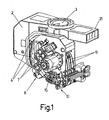
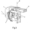
- the head is conventionally arranged on a rotary movement support (2) with respect to an assembly coupling (3) of vertical axis III, whereas the block (2.1) or actual head is incorporated in "pinion-crown" rotary assembly (4) of the horizontal axis I on the mentioned support (2), see Figures 1 , 2 and 3 .
- At least two carbon strip feed reels (1) for feeding the carbon strips to be applied are arranged in the head.
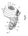
- the head has, as is seen in Figure 10 , four reels (1), on each of which a carbon-fibre strip with a width measurement of 75 mm is wound.
- the head applies the four carbon-fibre strips at the same time it achieves covering a width of 300 mm and thereby maximum productivity; whereas if only one 75 mm wide reel (1) is used very closed radii can be traced without producing wrinkles; thus one, two or three or the four reels (1) will be used according to the curvature of the radii to be traced.
- the head When the head is used to cover less complex surfaces, it is possible to use, for example, two 150 mm reels (1), covering a size in width of 300 mm, or even a single 300 mm wide reel (1) which allows developing curves with large radii for virtually planar parts.
- the reels (1) are incorporated on a master roller (5) which is formed by a makeup of independent consecutive rings (5.1) which are assembled on a shaft (16), see Figure 9 , the theoretical longitudinal axis II of which is perpendicular to the horizontal axis I.
- the rings (5.1) are associated by means of respective rotary actuation transmissions (6), in relation to corresponding independent motors (7) which are controlled by a computer programme.
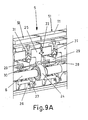
- the mentioned portions (5.1) of the master roller (5) are separated from one another by means of ball bearings (23) arranged between the side contact faces of the consecutive portions (5.1), allowing the independent rotation of each of them, see Figure 9 and 9A .
- each of the portions (5.1) is controlled by its respective independent motor (7) which, as is seen in Figure 9A , actuates a pinion (24) meshed with a crown (25) of the inside of the corresponding portion (5.1), such that the individual controlled rotation actuation of each portion (5.1) is ensured with this assembly, as described in Patent P200200524 of the same applicant as the present invention.
- the reels (1) can thus rotate at different speeds in relation to one another, such that, for example, upon reaching a curved portion, the reel (1) corresponding to the strip which is on the outside of the curve "will run" more than the wheel which is next to it, and so on and so forth, such that all the reels are unwound at the same speed when leaving the curve.
- the carbon-fibre strips intended for the application are provided with the corresponding conventional protective paper preventing said strips from becoming stuck together when being wound on the reels (1), such that when said strips are applied on the surface to be formed, the protective paper is separated therefrom, being collected in take-up spools (8) which are arranged for that purpose in the same head, see Figure 13 .
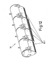
- the carbon-fibre strips are conveyed from the feed reels (1) incorporated on the master roller (5) by guides (9), see Figure 1 , which keep them separate until reaching the application area where there is arranged a multiple heel (10) which is formed, as seen in Figure 12 , by independent pressure portions (10.1) for pressing on each of the strips, such that the application of each strip is applied or not on the surface to be formed by means of stripping according to said pressure.
- the carbon-fibre strip feed reels (1) are assembled by means of an axial positioning arrangement by means of a longitudinal drive screw, in combination with optical sensors arranged in the guides (9) for conveying the strips, which allows performing an automatic control to align the strip feed reels (1) in correspondence with the respective guides (9).
- Each of the portions (5.1) making up the master roller (5) is furthermore provided on its contour (see Figures 8 to 9A ) with plates (11) susceptible of radial movement by means of a pneumatic system, such that a diametrical expansion of the mentioned portions (5.1) is produced by means of said plates (11) to fix thereon the reels (1), whereby the actuation of the strip feed for the application is actuated by means of the rotary transmission which is supplied to the portions (5.1) with the corresponding motors (7).
- a part (31) provided at the end with a ball which is arranged in a radial direction, such that the longitudinal movement of the bevelled ring (29), caused by the pneumatically actuated axial movement of the jacket (27), causes the movement of the part (31) in a radial direction, since its end slides on the ramp of the bevelled ring (29), pushing said part (31) to the plate (11) arranged thereon.
- Axial groovings are furthermore provided on the outer contour of the portions (5.1), by means of which perfect locking of the reels (1) on said portions (5.1) is ensured, preventing the relative rotary sliding to ensure perfect control of the reels (1).
- take-up spools (8) for taking up the protective paper of the carbon-fibre strips are incorporated, as seen in Figure 13 , on a shaft (12), being locked with respect thereto by means of a system of wedges (13) which are in turn actuated by means of a pneumatic system.
- sensors (14), depicted in Figure 11 are arranged through which the carbon-fibre strips pass individually, such that the exit speed of each of the strips is controlled by means of said sensors (14), the actuation of the rotary transmission to the reels (1) by means of the corresponding motors (7) being regulated according to such speed to adjust the feed of each strip to the application speed for applying the same which is required at all times, preventing the occurrence of tension or pulling which causes a poor application.
- the mentioned sensors (14) are furthermore arranged in an oscillating movement arrangement, which allows offsetting the variation of inertia of the reels (1) as the corresponding strip on said reels (1) is consumed, so that the tension of the strip is constant during the feed process, such that the application is uniform.
- the application method for applying the carbon-fibre strips according to the system of the invention can be carried out by means of the described head, using two or more strips with a total width equivalent to the width of the stripping which allows covering the application surface with a minimum number of passes, but such that by controlling the speed for feeding each of the strips, the strips can be applied following the necessary straight and curved paths, such that in the straight application areas all the strips are fed at the same speed, but in the curved application areas the strips for application in the outer part of the curvature are fed at a higher speed than the strips for application in the inner part of the curvature, so that the application is uniform in the entire width of the application, without stretching the strips in the outer part and wrinkling them in the inner part.
- the application process can be established such that when a reel (1) runs out, said reel (1) is replaced individually, continuing with the rest of the reels (1) in the process until each of them runs out, to replace them individually in the same way.
- this method the total exploitation of the carbon-fibre strips is achieved, but the process must be stopped many times to change each of the reels (1) when they run out.
- the application method can likewise be established to replace all the carbon-fibre strip feed reels (1) when one of them runs out, whereby the number of stops needed is reduced, since all the reels (1) are changed in each replacement stop and therefore all of them resume the feed process starting from a situation in which they are completely filled. With this method there is however a loss of material, since all the remaining content of the unfinished reels (1) is disposed of when the replacement is carried out upon any reel (1) running out.
- a management software program in combination with a programme of successive application uses to form similar or different parts is applied, such that said software calculates the run length for applying the stripping which must be carried out in the different uses, determining an order for performing them, such that the greater consumption of some strips for application in some uses is offset with the greater consumption of the other strips in other uses, whereby all the reels (1) holding the strips for application run out at the same time. With this method all the reels (1) are changed in the same replacement stop, the carbon-fibre material of the strips furthermore being totally exploited, since there is no disposal waste.
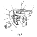
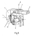
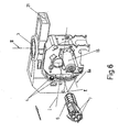
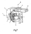
- an ultrasound cutting unit (15) is incorporated in the head, which is arranged in an axis IIa parallel to axis II of the master roller (5), oriented towards the side of the head, see Figure 4 , 5 and 6 .
- the cutting unit (15) has a rotation (CU) of the blade (17) by means of servo-controlled actuation which is actuated by a servomotor (18) through a pinion (19) and a crown (20), such that it is possible to thus cut the carbon-fibre material.
- the blade (17) is axially excited by an ultrasonic frequency with an amplitude of a few tenths of a millimeter by means of which it can cut the remaining deposited and uncured material from the carbon-fibre strips, said frequency of the blade (17) being generated by a resonator (21) which is incorporated in the support (2) of the head, from which it is transmitted to a collector (22), which allows exciting the blade (17) even when it is rotationally actuated in the rotation (CU).
Landscapes
- Engineering & Computer Science (AREA)
- Mechanical Engineering (AREA)
- Chemical & Material Sciences (AREA)
- Composite Materials (AREA)
- Robotics (AREA)
- Moulding By Coating Moulds (AREA)
- Reinforced Plastic Materials (AREA)
Applications Claiming Priority (2)
| Application Number | Priority Date | Filing Date | Title |
|---|---|---|---|
| ES200602154A ES2291131B1 (es) | 2006-08-08 | 2006-08-08 | Cabezal de aplicacion de cintas de fibra de carbono y metodo de aplicacion. |
| PCT/ES2007/000382 WO2008020094A1 (fr) | 2006-08-08 | 2007-06-28 | Tête d'application de rubans de fibre de carbone et procédé d'application correspondant |
Publications (2)
| Publication Number | Publication Date |
|---|---|
| EP2055463A1 true EP2055463A1 (fr) | 2009-05-06 |
| EP2055463A4 EP2055463A4 (fr) | 2014-02-19 |
Family
ID=39031179
Family Applications (1)
| Application Number | Title | Priority Date | Filing Date |
|---|---|---|---|
| EP07788630.7A Withdrawn EP2055463A4 (fr) | 2006-08-08 | 2007-06-28 | Tête d'application de rubans de fibre de carbone et procédé d'application correspondant |
Country Status (6)
| Country | Link |
|---|---|
| US (1) | US8202385B2 (fr) |
| EP (1) | EP2055463A4 (fr) |
| JP (1) | JP5517618B2 (fr) |
| CN (1) | CN101500786B (fr) |
| ES (1) | ES2291131B1 (fr) |
| WO (1) | WO2008020094A1 (fr) |
Cited By (1)
| Publication number | Priority date | Publication date | Assignee | Title |
|---|---|---|---|---|
| FR3063673A1 (fr) * | 2017-03-13 | 2018-09-14 | Institut De Recherche Technologique Jules Verne | Plateforme mobile pour robot parallele a cables, robot parallele a cables, installation et procede de drapage a l'aide d'un tel robot |
Families Citing this family (11)
| Publication number | Priority date | Publication date | Assignee | Title |
|---|---|---|---|---|
| ES2331825B1 (es) * | 2007-10-08 | 2010-07-22 | Manuel Torres Martinez | Perfeccionamientos en cabezales de aplicacion de cintas de fibra. |
| US8557074B2 (en) * | 2008-02-27 | 2013-10-15 | The Boeing Company | Reduced complexity automatic fiber placement apparatus and method |
| FR2981000B1 (fr) * | 2011-10-06 | 2013-11-29 | Snecma | Dispositif pour la fabrication d'une piece en materiau composite |
| US20140255646A1 (en) * | 2013-03-08 | 2014-09-11 | The Boeing Company | Forming Composite Features Using Steered Discontinuous Fiber Pre-Preg |
| JP6185350B2 (ja) * | 2013-09-24 | 2017-08-23 | 東邦テナックス株式会社 | プリプレグ自動積層装置、プリプレグ積層体の製造方法及び繊維強化複合材料製造装置 |
| US10625477B2 (en) | 2014-09-25 | 2020-04-21 | Toray Industries, Inc. | Reinforcing fiber sheet manufacturing apparatus |
| FR3059932B1 (fr) * | 2016-12-09 | 2021-01-29 | Inst De Rech Tech Jules Verne | Cassette, tete de depose comportant une telle cassette, installation, procede de drapage, procede de rechargement et procede de preparation |
| KR101980145B1 (ko) * | 2017-08-31 | 2019-05-20 | 고대운 | 탄소섬유 공급설비 |
| CN110723597A (zh) * | 2019-10-22 | 2020-01-24 | 苏州市职业大学 | 一种连续缠带设备 |
| KR102498897B1 (ko) * | 2021-11-24 | 2023-02-10 | 강영길 | 와인딩머신용 필라멘트 핸들링유니트 |
| FR3131706B1 (fr) * | 2022-01-12 | 2024-08-23 | Safran | Tête d’application pour le placement automatique de fibres |
Family Cites Families (21)
| Publication number | Priority date | Publication date | Assignee | Title |
|---|---|---|---|---|
| US2122292A (en) * | 1937-09-21 | 1938-06-28 | James Joseph Lannon | Carrier for braiding machines |
| US2436067A (en) * | 1945-07-26 | 1948-02-17 | Nye Wait Company Inc | Tension regulator and equalizer for pile fabric looms |
| US3122872A (en) * | 1962-09-24 | 1964-03-03 | Gen Motors Corp | Flexible cable winding machine |
| US3810805A (en) * | 1972-04-14 | 1974-05-14 | Goldsworthy Eng Inc | Geodesic path length compensator for composite-tape placement head |
| US4292108A (en) * | 1979-12-10 | 1981-09-29 | General Dynamics Corporation | Composite tape laying apparatus including means for plural longitudinal and transverse cuts |
| US4461669A (en) * | 1983-09-30 | 1984-07-24 | The Boeing Company | Pivotal mount for laminating head |
| JPS61290038A (ja) * | 1985-06-19 | 1986-12-20 | Agency Of Ind Science & Technol | Frpテ−プの自動貼着方法および装置 |
| US4699683A (en) * | 1986-02-07 | 1987-10-13 | The Boeing Company | Multiroving fiber laminator |
| JPS63229297A (ja) * | 1987-03-19 | 1988-09-26 | 工業技術院長 | Frpテ−プの自動切断装置 |
| US4943338A (en) * | 1988-09-26 | 1990-07-24 | Cincinnati Milacron Inc. | Multi-tow fiber placement machine with full band width clamp, cut, and restart capability |
| US5110395A (en) * | 1989-12-04 | 1992-05-05 | Cincinnati Milacron Inc. | Fiber placement head |
| JPH0639133B2 (ja) * | 1990-06-27 | 1994-05-25 | 川崎重工業株式会社 | ロービング材自動積層装置 |
| JPH0483714U (fr) * | 1990-11-30 | 1992-07-21 | ||
| ES2114413B1 (es) * | 1994-10-07 | 1999-02-16 | Torres Martinez M | Cabezal para la aplicacion de bandas de composite. |
| AU1360199A (en) * | 1997-11-05 | 1999-05-24 | Sikorsky Aircraft Corporation | Feed control system for fiber placement machines |
| US6544367B1 (en) * | 1999-02-01 | 2003-04-08 | Alliant Techsystems Inc. | Overwrap tape end-effector for fiber placement/winding machines |
| JP2002137241A (ja) * | 2000-11-06 | 2002-05-14 | Mitsubishi Heavy Ind Ltd | 自動積層成形装置及び成形方法 |
| US6799081B1 (en) * | 2000-11-15 | 2004-09-28 | Mcdonnell Douglas Corporation | Fiber placement and fiber steering systems and corresponding software for composite structures |
| ES2212878B1 (es) * | 2002-03-05 | 2005-07-16 | Manuel Torres Martinez | Cabezal multiaplicador de tiras de fibra. |
| JP3632177B2 (ja) * | 2002-11-29 | 2005-03-23 | 川崎重工業株式会社 | プリプレグ幅変更自動積層方法及びその装置 |
| ES2246713B1 (es) * | 2004-07-27 | 2006-12-01 | Manuel Torres Martinez | "mejoras en un cabezal multiaplicador de tiras de fibra". |
-
2006
- 2006-08-08 ES ES200602154A patent/ES2291131B1/es not_active Expired - Fee Related
-
2007
- 2007-06-28 CN CN2007800293161A patent/CN101500786B/zh not_active Expired - Fee Related
- 2007-06-28 JP JP2009523309A patent/JP5517618B2/ja not_active Expired - Fee Related
- 2007-06-28 WO PCT/ES2007/000382 patent/WO2008020094A1/fr not_active Ceased
- 2007-06-28 US US12/309,972 patent/US8202385B2/en not_active Expired - Fee Related
- 2007-06-28 EP EP07788630.7A patent/EP2055463A4/fr not_active Withdrawn
Cited By (2)
| Publication number | Priority date | Publication date | Assignee | Title |
|---|---|---|---|---|
| FR3063673A1 (fr) * | 2017-03-13 | 2018-09-14 | Institut De Recherche Technologique Jules Verne | Plateforme mobile pour robot parallele a cables, robot parallele a cables, installation et procede de drapage a l'aide d'un tel robot |
| WO2018166926A1 (fr) * | 2017-03-13 | 2018-09-20 | Institut De Recherche Technologique Jules Verne | Plateforme mobile pour robot parallele a cables, robot parallele a cables, installation et procede de drapage a l'aide d'un tel robot |
Also Published As
| Publication number | Publication date |
|---|---|
| JP5517618B2 (ja) | 2014-06-11 |
| JP2010500191A (ja) | 2010-01-07 |
| US8202385B2 (en) | 2012-06-19 |
| WO2008020094A1 (fr) | 2008-02-21 |
| CN101500786A (zh) | 2009-08-05 |
| ES2291131B1 (es) | 2008-12-01 |
| EP2055463A4 (fr) | 2014-02-19 |
| US20090266485A1 (en) | 2009-10-29 |
| CN101500786B (zh) | 2012-11-28 |
| ES2291131A1 (es) | 2008-02-16 |
Similar Documents
| Publication | Publication Date | Title |
|---|---|---|
| US8202385B2 (en) | Head for application of carbon-fibre strips and application method | |
| US8156988B2 (en) | Fiber strip multiapplicator head and method for applying the fiber strips | |
| US4557790A (en) | Tape laminator | |
| JP6110477B2 (ja) | プリプレグテープのスリット加工の装置及び方法 | |
| EP3278964B1 (fr) | Dispositif d'alimentation pour un matériau de fibre de renforcement et procédé pour couper un matériau de fibre de renforcement au moyen du dispositif d'alimentation | |
| JP2015507555A (ja) | 無端の補強ベルトを製造するための装置及び方法 | |
| CA2563784A1 (fr) | Execution d'evenements a grande vitesse 'a la volee'' pendant la fabrication d'une structure composite par un placement automatise des fibres | |
| JP2005528257A (ja) | 細帯体の方向転換機構を備えたタイヤ補強構造物の製造装置 | |
| US5145543A (en) | Combination filament winding and tape laying apparatus and method for making and using the same | |
| US6969438B2 (en) | High-speed cutting device and method for cutting a tire reinforcement | |
| US4517872A (en) | Controlled depth cutting method and apparatus | |
| US8038825B2 (en) | Fibre strip application heads | |
| NZ206517A (en) | Forming ring or sheet of unvulcanised rubber for pneumatic tyre by helically winding strip upon mandrel | |
| CA2997075C (fr) | Methode d'exploitation d'une machine de placement de fibre automatisee | |
| US7399374B2 (en) | System for producing a reinforcing structure for a tire with volumetric control | |
| JP4902549B2 (ja) | タイヤの周方向補強材を製造して配置する方法及び装置並びにこの方法により得られたタイヤ | |
| EP3826827A1 (fr) | Procédé et équipement de fabrication de pneumatiques pour roues de véhicule | |
| US3707415A (en) | Filament winding | |
| US1628836A (en) | Apparatus for forming and cutting plastic material | |
| JP4402415B2 (ja) | タイヤ用コード補強層の形成方法およびコード補強層形成装置 | |
| CN102463684B (zh) | 轮胎用帘布材料的制造方法 | |
| WO2020021391A1 (fr) | Procédé et équipement de fabrication de pneumatiques pour roues de véhicule | |
| EP2982631A1 (fr) | Bras de va-et-vient et machine de bobinage de fil | |
| EP3697604B1 (fr) | Production d'un produit semi-fini stratifié destiné à être utilisé dans la production de pneus | |
| JP2001145953A (ja) | 巻成されたスリーブを帯材料から連続的にエンドレスに製造する方法および装置 |
Legal Events
| Date | Code | Title | Description |
|---|---|---|---|
| PUAI | Public reference made under article 153(3) epc to a published international application that has entered the european phase |
Free format text: ORIGINAL CODE: 0009012 |
|
| 17P | Request for examination filed |
Effective date: 20090306 |
|
| AK | Designated contracting states |
Kind code of ref document: A1 Designated state(s): AT BE BG CH CY CZ DE DK EE ES FI FR GB GR HU IE IS IT LI LT LU LV MC MT NL PL PT RO SE SI SK TR |
|
| AX | Request for extension of the european patent |
Extension state: AL BA HR MK RS |
|
| RBV | Designated contracting states (corrected) |
Designated state(s): DE FR GB |
|
| DAX | Request for extension of the european patent (deleted) | ||
| A4 | Supplementary search report drawn up and despatched |
Effective date: 20140117 |
|
| RIC1 | Information provided on ipc code assigned before grant |
Ipc: B29C 70/54 20060101ALI20140113BHEP Ipc: B29C 53/80 20060101ALI20140113BHEP Ipc: B29C 70/38 20060101AFI20140113BHEP |
|
| GRAP | Despatch of communication of intention to grant a patent |
Free format text: ORIGINAL CODE: EPIDOSNIGR1 |
|
| RIC1 | Information provided on ipc code assigned before grant |
Ipc: B29C 70/38 20060101AFI20180205BHEP Ipc: B29C 53/80 20060101ALI20180205BHEP Ipc: B29C 70/54 20060101ALI20180205BHEP |
|
| INTG | Intention to grant announced |
Effective date: 20180308 |
|
| STAA | Information on the status of an ep patent application or granted ep patent |
Free format text: STATUS: THE APPLICATION IS DEEMED TO BE WITHDRAWN |
|
| 18D | Application deemed to be withdrawn |
Effective date: 20180719 |