EP1775202A2 - Fahrerhaus einer Arbeitsmaschine - Google Patents
Fahrerhaus einer Arbeitsmaschine Download PDFInfo
- Publication number
- EP1775202A2 EP1775202A2 EP06120921A EP06120921A EP1775202A2 EP 1775202 A2 EP1775202 A2 EP 1775202A2 EP 06120921 A EP06120921 A EP 06120921A EP 06120921 A EP06120921 A EP 06120921A EP 1775202 A2 EP1775202 A2 EP 1775202A2
- Authority
- EP
- European Patent Office
- Prior art keywords
- plate members
- plate member
- cab
- support pillar
- working machine
- Prior art date
- Legal status (The legal status is an assumption and is not a legal conclusion. Google has not performed a legal analysis and makes no representation as to the accuracy of the status listed.)
- Ceased
Links
- 230000013011 mating Effects 0.000 claims description 2
- 238000003466 welding Methods 0.000 description 29
- 239000000470 constituent Substances 0.000 description 11
- 238000005304 joining Methods 0.000 description 10
- 238000010586 diagram Methods 0.000 description 4
- 230000033001 locomotion Effects 0.000 description 3
- 238000000034 method Methods 0.000 description 3
- 230000003247 decreasing effect Effects 0.000 description 2
- 238000004519 manufacturing process Methods 0.000 description 2
- 241001184547 Agrostis capillaris Species 0.000 description 1
- 208000019901 Anxiety disease Diseases 0.000 description 1
- 230000036506 anxiety Effects 0.000 description 1
- 230000002093 peripheral effect Effects 0.000 description 1
- 230000003014 reinforcing effect Effects 0.000 description 1
- 238000003860 storage Methods 0.000 description 1
- 238000005728 strengthening Methods 0.000 description 1
- 238000006467 substitution reaction Methods 0.000 description 1
Images


Classifications
-
- B—PERFORMING OPERATIONS; TRANSPORTING
- B62—LAND VEHICLES FOR TRAVELLING OTHERWISE THAN ON RAILS
- B62D—MOTOR VEHICLES; TRAILERS
- B62D33/00—Superstructures for load-carrying vehicles
- B62D33/06—Drivers' cabs
- B62D33/0617—Drivers' cabs for tractors or off-the-road vehicles
Definitions
- the present invention relates to a cab of a working machine such as a hydraulic excavator.
- a cab of a working machine encloses an operator's seat to protect the same seat. More particularly, the cap is provided with plural support pillars erected around the operator's seat.
- each constituent plate cannot be set to a larger value than the thickness which permits the press working. Thus, a limit is encountered in point of the pillar strength. Further, since the constituent plates of this support pillar are joined intermittently in the longitudinal direction, joining strength between plates is weak.
- the cab of a working machine according to the present invention has the following basic configuration.
- the cab of a working machine has plural support pillars erected around an operator's seat of the working machine and encloses the operator's seat to protect the same seat.
- At least one of the support pillars is configured by a combined support pillar formed by combining plural plate members extending in the longitudinal direction of the support pillar concerned to define a closed section. In the closed section, an end face in the transverse direction of one of adjacent plate members is abutted against an inner surface of the other plate member and in this state the abutted portion of the plate members is fillet-welded substantially throughout the overall length of each of the plate members.
- a specific support pillar is formed using plural plate members and has a configuration such that an end face in the transverse direction of one of adjacent plate members of the plate members is abutted against an inner surface of the other plate member and in this state both are welded together.
- the sectional shape can be changed relatively freely while ensuring the strength required of this combined support configuration.
- the sectional shape, etc. can be changed relatively freely by for example selecting suitable plate members or changing the position where plate members are to be joined.
- a support pillar of a different sectional shape can be formed by changing the position where the plate members are to be welded.
- the combined support pillar is formed using plural plate members, so unlike the case of forming the support pillar with use of a pipe member, the sectional shape (including thickness and outline) of each plate member can be changed relatively freely and thus support pillars of various sectional shapes can be formed by such changing of the sectional shape.
- adjacent plates are spot-welded intermittently in the longitudinal direction in a state where allowances for welding of the plates are in surface-contact with each other.
- an end face of one of plate members adjacent to each other in a closed section is abutted against an inner surface of the other plate member and in this state the plate members are fillet-welded throughout the overall length of the plate members, so that it is possible to ensure a sufficient joining strength between the plate members.
- the combined support pillar includes a support pillar erected behind the operator's seat.
- the support pillar disposed behind the operator's seat is required to have a high strength and it is possible to meet flexibly both requirement for the strength and requirement for the shape in the limited space, for example, by selecting suitable plate members or changing the position where plate members are to be joined.
- the plate members include a pair of opposed plate members disposed so that respective inner surfaces confront each other and a pair of interposing plate members interposed between the inner surfaces of the opposed plate members, and a closed section of a quadrangular shape is formed by the opposed plate members and the interposing plate members.
- two interposing plate members are interposed between both opposed plate members, so when an external force is applied to one of the opposed plate members, the external force can be transmitted to the other of the opposed plate members through the interposing plate members. Therefore, when a high strength is required against an external force acting in a specific direction, the foregoing requirements can be met by disposing the opposed plate members so as to intersect the above-mentioned direction.
- the opposed plate members prefferably be disposed in such a manner that the respective inner surfaces confront each other in the longitudinal direction of the working machine.
- the plate members include a plate member having at least one bent portion in the closed section.
- At least two of the side faces of the support pillar can be formed by a single plate member, so that the number of the plate member welding steps can be reduced in comparison with the case where the two faces are formed by welding two plate members, and thus the working efficiency in manufacturing the support pillar can be improved.
- the joining strength can be improved to a greater extent than in case of performing the fillet welding on one of the surface and the back.
- a hydraulic excavator 1 as an example of a working machine includes a lower traveling body 2 having crawlers 2a, an upper rotating body 3 mounted rotatably on the lower traveling body 2, and an attachment 4, the attachment being attached to a front portion of the upper rotating body 3 so that it can rise and fall.
- the attachment 4 is made up of a boom 5 and an arm 6 connected to a front end of the boom 5, with a bucket 7 being mounted pivotably to a front end of the arm 6.
- the boom 5 is adapted to rise and fall with extending and retracting motions of the a boom cylinder 8
- the arm 6 is adapted to move pivotally with extending and retracting motions of an arm cylinder 9
- the bucket 7 is adapted to move pivotally relative to the arm 6 with extending and retracting motions of a bucket cylinder 10.
- a cab 11 which encloses an operator's seat (not shown) to protect the same seat.
- front, rear and right, left directions are directions as seen by the eyes of an operator sitting on the operator's seat.
- Fig. 2 is a perspective view showing the enlarged cab 11 shown in Fig. 1.
- Fig. 3 is a sectional taken on line III-III in Fig. 2.
- the cab 11 includes a frame 50 which configures the profile of the cab, panels (indicated at 12a, 31 and 32 in the figures) which are secured to the frame 50 outside or inside the frame to define an operator room, and rails 37 disposed inside the frame 50 (within the operator room).
- the frame 50 comprises a front section 12 and a back section 14, both sections 12 and 14 being connected together longitudinally.
- the front section 12 includes a right front support pillar 15, a left front support pillar 16, the pillars 15 and 16 being erected in front of the operator's seat (not shown), a front connecting frame 17 for connecting lower end portions of the support pillars 15 and 16 in the transverse direction, and a right front frame 18, and a left front frame 19, the frames 18 and 19 extending backward from the lower end portions of the support pillars 15 and 16.
- the right front support pillar 15 comprises thin plates 15a and 15b having been subjected to press working.
- the thin plates 15a and 15b are joined together to form a closed section. More specifically, the thin plates 15a and 15b are spot-welded intermittently in a state in which allowances 15A and 15B for welding formed longitudinally on both sides in the transverse direction of the thin plates are in surface-contact with each other.
- Sectional shapes of the right and left support pillars 15 and 16 are symmetric right and left and therefore an explanation of the left front support pillar 16 will be omitted.
- both front support pillars 15 and 16 extend upward from a base 3a of the upper rotating body 3 and are bent backward and their rear end portions are joined to the back section 14.
- the right and left front frames 18 and 19 extend backward from the lower end portions of the front support pillars 15 and 16 respectively and their rear end portions are joined to the back section 14.
- Fig. 4 is a perspective view showing the configuration of the back section of Fig. 2
- Fig. 5 is a side view of the back section of Fig. 4
- Fig. 6 is a plan view of the back section of Fig. 4.
- the back section 14 includes a left mounting plate 27a, a right mounting plate 27b, both plates 27a and 27b being fixed onto the base 3a of the upper rotating body 3, a mid-left support pillar 20, a mid-right support pillar 21, the support pillars 20 and 21 being erected on front portions of the mounting plates 27a and 27b respectively, a rear left support pillar 22, a rear right support pillar 23, the support pillars 22 and 23 being erected on rear portions of the mounting plates 27a and 27b respectively, and connecting frames for connecting the support pillars 20 to 23.
- the connecting frames include an upper left frame 28a for connecting upper end portions of the mid-left support pillar 20 and the rear left support pillar 22 with each other longitudinally, lower left frames 25a and 25b provided in a pair of upper and lower frames for connecting lower portions of the support pillars 20 and 22 with each other, an upper right frame 28b for connecting upper end portions of the mid-right support pillar 21 and the rear right support pillar 23 with each other longitudinally, lower right frames 24a and 24b provided in a pair of upper and lower frames for connecting lower portions of the support pillars 21 and 23 with each other longitudinally, a rear upper frame 30 for connecting upper end portions of the rear left support pillar 22 and the rear right support pillar 23 with each other transversely, rear mid-frames 26a and 26b provided in a pair of upper and lower frames for connecting intermediate portions of the support pillars 22 and 23 with each other transversely, a rear lower frame 26c for connecting lower portions of the support pillars 22 and 23 with each other transversely, and three longitudinally juxtaposed
- the mid-right support pillar 21 is a pipe member of a generally rectangular section whose length direction corresponds to the longitudinal direction.
- the mid-left support pillar 20 also has the same closed section and therefore an explanation thereof is here omitted.
- the rear end portions of the front support pillars 15 and 16 are joined to upper portions of the support pillars 20 and 21 respectively, while the rear end portions of the right and left front frames 18 and 19 are joined to lower portions of the pillars 20 and 21 respectively.
- the rear left support pillar 22 and the rear right support pillar 23 (hereinafter referred to generically as the rear support pillars 22 and 23 unless distinction is needed) have a side shape such that they extend upward from the mounting plates 27a and 27b respectively, then their upper portions are inclined forward and their upper end portions extend upward.
- the rear support pillars 22 and 23 are each formed so as to have a generally square closed section by combining four plate members 33 to 36 which extend in the longitudinal direction of the rear support pillars 22 and 23.
- the rear right support pillar 23 comprises a right plate member (interposing plate member) 33, a left plate member (interposing plate member) 34, the right and left plate members 33 and 34 having a planar shape corresponding to the side shape of the rear right support pillar 23, a front plate member (opposed plate member) 35, and a rear plate member (opposed plate member) 36, the front and rear plate members 35 and 36 sandwiching the right and left plate members 33 and 34 longitudinally.
- An upper end portion of the right plate member 33 is formed as a lid portion 33a which is bent leftwards. Peripheral portions of the lid portion 33a are welded to an upper end face of the left plate member 34, an inner surface (rear surface) 35a of the front plate member 35 and an inner surface (front surface) 36a of the rear plate member 36, thereby closing an upper opening of the rear right support pillar 23.
- a front end face 33b in the width direction (longitudinal direction) of the right plate member 33 is abutted against the inner surface 35a of the front plate member 35 and in this state there is performed fillet welding S1 throughout the overall length of the inner surface 35a, whereby the right plate member 33 is joined to the front plate member 35.
- a rear end face 33c of the right plate member 33 is abutted against the inner surface 36a of the rear plate member 36 and in this state there is performed fillet welding S2 throughout the overall length of the inner surface 36a, whereby the right plate member 33 is joined to the rear plate member 36.
- the width size (longitudinal size) of the left plate member 34 is set almost equal to that of the right plate member 33.
- a front end face 34b in the width direction of the left plate member 34 is abutted against the inner surface 35a of the front plate member 35 and in this state there is performed fillet welding S3 throughout the overall length of the inner surface 35a, whereby the left plate member 34 is jointed to the front plate member 35.
- a rear end face 34c of the left plate member 34 is abutted against the inner surface 36a of the rear plate member 36 and in this state there is performed fillet welding S4 throughout the overall length of the inner surface 36a, whereby the left plate member 34 is joined to the rear plate member 36.
- the front plate member 35 is curved correspondingly to the side shape of the front end faces 33b and 34b of the right and left plate members 33 and 34
- the rear plate member 36 is curved correspondingly to the side shape of the rear end faces 33c and 34c of the right and left plate members 33 and 34.
- the rear left support pillar 22 is different from the rear right support pillar 23 only in that the lid portion 33a is formed on the left plate member 34, and other configuration points are the same as those of the rear right support pillar 23, and therefore an explanation of the rear left support pillar 22 is here omitted.
- the rails 37 support a front window (not shown) slidably on both right and left sides, the front window being disposed in a front portion of the cab 11.
- the rails 37 are provided on the right and left within the cab 11 (only one is shown in Fig. 3).
- the rails 37 extend upward along inner side faces (the operator room side) of the front support pillars 15 and 16, then are bent rearwards, pass inside the mid-support pillars 20 and 21, and their rear end portions extend up to positions near the front sides of the rear support pillars 22 and 23.
- the front window (not shown) can be slid between a basic attitude thereof wherein it is located in the front portion of the cab 11 and a storage attitude thereof wherein it is located inside an upper portion of the cab 11.
- the rear support pillars 22 and 23 are each formed by four plate members 33 to 36 and fillet weldings S1 to S4 are performed in a state in which end faces 33b, 33c, 34b and 34c of the plate members 33 and 34 are abutted against the inner surfaces 35a and 36a of the plate members 35 and 36. According to this configuration, the sectional shape can be changed relatively freely while ensuring the strength required of the support pillar concerned.
- end faces 33b, 33c, 34b and 34c of the plate members 33 and 34 out of the four plate members 33 to 36 which configure the rear support pillars 22 and 23 are welded to the inner surfaces 35a and 36a of the plate members 35 and 36 adjacent thereto, so that the sectional shape, etc. can be changed relatively freely, for example, by selecting suitable plate members 33 to 36 or by changing the positions of fillet weldings S 1 to S4.
- the front and rear plate members 35 and 36 are of the same shape in the above embodiment. But also in this case the sectional shape of the rear support pillars 22 and 23 can be changed by changing the positions of fillet weldings S1 to S4 without changing the shape of the front and rear plate members 35 and 36.
- the rear support pillars 22 and 23 are each formed by plural plate members 33 to 36. Therefore, in comparison with the case where the rear support pillars 22 and 23 are each formed using a pipe member, the sectional shape of each of the plate members 33 to 36 can be changed relatively freely and rear support pillars 22 and 23 of various sectional shapes can be formed by such changing of the sectional shape.
- the sectional shape of a pipe member is made into a shape capable of avoiding interference with constituent parts, i.e., a deformed section, and then enlarge the sectional area.
- the pipe member itself of such a specific specification as a deformed section is expensive and causes an increase of cost.
- the thickness of the pipe member is limited to a predetermined small value and hence it becomes difficult to achieve the object of the present invention, i.e., strengthening the pipe member.
- the sectional shape (including thickness and outline) of each of the plate members 33 to 36 and the positions to be joined by fillet weldings S1 to S4 can be changed relatively freely, whereby the sectional shape and strength of the rear support pillars 22 and 23 can be adjusted. Therefore, the foregoing limitations imposed in case of adopting a pipe member can be avoided.
- the plates are spot-welded intermittently in the longitudinal direction in a state in which allowances for welding (15A and 15B in Fig. 8A) of plates are in surface-contact with each other.
- the rear support pillars 22 and 23 of the cab 11 end faces of plate members 33 and 34 which are adjacent to each other in a closed section are abutted against the inner surfaces 35a and 36a of the plate members 35 and 36 and in this state fillet weldings S 1 to S4 are performed for the plate members 33 to 36 throughout the overall length of each plate member. Consequently, it is possible to ensure a sufficient joining strength among the plate members 33 to 36.
- the end faces 33b, 33c, 34b and 34c of the plate members 33 and 34 are abutted against the inner surfaces 35a and 36a of the plate members 35 and 36 and welding is performed in this state. Also by this abutment the section modulus of the rear support pillars 22 and 23 can be made large.
- each of the left and right rear support pillars 22 and 23 is formed by the plate members 33 to 36, only one of the rear support pillars may be formed by the plate members 33 to 36.
- any or all of the right front support pillar 15, left front support pillar 16, mid-left support pillar 20, and mid-right support pillar 21, may be formed by the plate members 33 to 36.
- a concrete mode of the other support pillars than the support pillar (combined support pillar) formed by the plate members 33 to 36 is not specially limited, but may be set appropriately in accordance with desired conditions.
- rear support members 22 and 23 are not formed by the plate members 33 to 36, they may be formed by such a pipe member as shown in Fig. 8B.
- upper left frame 28a, upper right frame 28b, lower left frames 25a and 25b, lower right frames 24a and 24b, rear upper frame 30, rear mid-frames 26a and 26b, rear lower frame 26c, and upper frames 29a, 29b and 29c may each be formed by the plate members 33 to 36.
- the right and left plate members 33 and 34 are disposed bridgewise between the inner surfaces 35a and 36a of the front and rear plate members 35 and 36. Therefore, when an external force is applied to one of the front and rear plate members 35 and 36, the external force can be transmitted to the opposite-side plate member 35 or 36 through the right and left plate members 33 and 34. Consequently, the strength of the rear support pillars 22 and 23 can be improved against an external force applied thereto in the longitudinal direction.
- the above embodiment refers to the configuration wherein the rear end portions of the rails 37 and the rear support pillars 22 and 23 do not interfere with each other, as shown in Fig. 3.
- the positions where the rear support pillars 22 and 23 are to be erected, as well as the shape of those pillars are limited for example due to a requirement for the reduction in size of the cab 11.
- the rear support pillars 22 and 23 interfere with other constituent members, e.g., rails 37.
- the rear support pillars 22 and 23 interfere with the rails 37 longitudinally. Even in such a case, the interference between the rear support pillars 22 and 23 and the rails 37 can be avoided by forming a depression 39 in each of the rear support pillars 22 and 23.
- a curved recess 39a is formed in the front plate member 35 correspondingly to the shape of a side face of each rail 37 and cutout portions 39b and 39c are formed respectively in the right and left plate members 33 and 34 correspondingly to the curved recess 39a, whereby the depression 39 as a partial longitudinal depression can be formed in each of the rear support pillars 22 and 23.
- the rear support pillars 22 and 23 are each formed by a combination of the plate members 33 to 36. Before this combination, the surfaces of the plate members 33 to 36 which become inner surfaces after the combination may be subjected to various processing in advance.
- an L-shaped angle 40 may be provided bridgewise for two adjacent plate members (33 and 35 in Fig. 10) out of the plate members 33 to 36.
- the joining between the adjacent plate members 33 and 35 can be strengthened by the L-shaped angle 40 in addition to the fillet weldings S1 to S4 which join the plate members 33 to 36 with one another.
- the L-shaped angle 40 is to be provided throughout the overall length of the plate members 33 to 36 or partially in the longitudinal direction.
- a ⁇ -shaped reinforcing member may be provided, whereby the joining of three adjacent plate members can be strengthened.
- a nut 42 may be mounted (welded) to the surface of any of the plate members 33 to 36 (the inner surface 36a of the rear plate member 36 in Fig. 10) which becomes an inner surface after the combination.
- a bolt can be brought into threaded engagement with the nut 42 from the outside of the rear support pillar 22 (23) through a through hole 41 formed in the rear plate member 36.
- fillet welding S5 may be performed also for the inner surface of a specific plate member (the left plate member 34 in Fig. 10), whereby the joining strength of the specific plate member can be further improved.
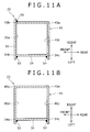
- the plate members 33 to 36 used in the above embodiment are of a rectilinear section, there also may be adopted such a bent plate member 43 of an L-shaped section as shown in Fig. 11A.
- the bent plate member 43 in its sectional shape, has constituent portions corresponding to the right plate member 33 and the rear plate member 36 integrally through a bent portion 43a.
- the reason why the right and rear plate members are formed integrally as shown in the drawing is that the rear support pillars 22 and 23 are required to have a sufficient strength against external forces exerted sideways and from behind.
- the bent portion 43a is not limited to one portion. As shown in Fig. 11B, there may be adopted a bent plate member 45 of a ⁇ -shaped section having two bent portions.
- the bent plate member 45 in its sectional shape, has constituent portions corresponding to the right plate member 33, front plate member 35 and rear plate member 36 integrally through a pair of bent portions 45a and 45b.
- Both front end and rear end faces 34b and 34c of the left plate member 34 are abutted against inner surfaces 45c and 45d which are opposed to each other longitudinally, and in this state there are performed fillet weldings S3 and S4, whereby the bent plate member 45 is joined to the left plate member 34 throughout the overall length of each plate member.
- the bent plate member 46 in its sectional shape, has constituent portions corresponding to the front plate member 35 and the left plate member 34 integrally through a bent portion 46a.
- the sectional shape of the rear support pillars 22 and 23 can be changed by changing the positions of fillet weldings S7 and S8, so that the strength and sectional shape of the rear support pillars 22 and 23 can be adjusted while using the common bent plate members 43 and 46.
- a rear support pillar is configured by combining plural plate members extending in the longitudinal direction of the support pillar to define a closed section. An end face of one of plate members adjacent to each other in the closed section is abutted against an inner surface of the other plate member and in this state the abutted portion of the plate members is fillet-welded throughout the overall length of each plate member.
Landscapes
- Engineering & Computer Science (AREA)
- Chemical & Material Sciences (AREA)
- Combustion & Propulsion (AREA)
- Transportation (AREA)
- Mechanical Engineering (AREA)
- Body Structure For Vehicles (AREA)
- Component Parts Of Construction Machinery (AREA)
Applications Claiming Priority (1)
| Application Number | Priority Date | Filing Date | Title |
|---|---|---|---|
| JP2005299739A JP2007106286A (ja) | 2005-10-14 | 2005-10-14 | 作業機械のキャブ |
Publications (2)
| Publication Number | Publication Date |
|---|---|
| EP1775202A2 true EP1775202A2 (de) | 2007-04-18 |
| EP1775202A3 EP1775202A3 (de) | 2008-05-28 |
Family
ID=37636116
Family Applications (1)
| Application Number | Title | Priority Date | Filing Date |
|---|---|---|---|
| EP06120921A Ceased EP1775202A3 (de) | 2005-10-14 | 2006-09-19 | Fahrerhaus einer Arbeitsmaschine |
Country Status (4)
| Country | Link |
|---|---|
| US (1) | US7413241B2 (de) |
| EP (1) | EP1775202A3 (de) |
| JP (1) | JP2007106286A (de) |
| CN (1) | CN1948637A (de) |
Cited By (3)
| Publication number | Priority date | Publication date | Assignee | Title |
|---|---|---|---|---|
| EP2154295A1 (de) * | 2008-08-11 | 2010-02-17 | Kobelco Construction Machinery Co., Ltd. | Kabine für Baumaschinen |
| US7887124B2 (en) * | 2005-07-19 | 2011-02-15 | Komatsu Ltd. | Cab structure for construction machine |
| EP3162669A4 (de) * | 2014-06-26 | 2018-03-21 | Yanmar Co., Ltd. | Nutzfahrzeug |
Families Citing this family (11)
| Publication number | Priority date | Publication date | Assignee | Title |
|---|---|---|---|---|
| JP2007107291A (ja) * | 2005-10-14 | 2007-04-26 | Kobelco Contstruction Machinery Ltd | 保護部材の取付構造及びこれを備えた作業機械 |
| KR100753991B1 (ko) * | 2006-09-22 | 2007-08-31 | 볼보 컨스트럭션 이키프먼트 홀딩 스웨덴 에이비 | 건설기계의 운전실 캡을 지지하는 상부 프레임 구조 |
| JP4994964B2 (ja) * | 2007-06-14 | 2012-08-08 | プレス工業株式会社 | 建設機械 |
| JP5157403B2 (ja) * | 2007-12-05 | 2013-03-06 | コベルコ建機株式会社 | 上部体及びこれを備えた建設機械 |
| US9235644B2 (en) * | 2008-07-14 | 2016-01-12 | Qualcomm Incorporated | Operator, device and platform independent aggregation, cross-platform translation, enablement and distribution of user activity catalogs |
| US8579363B2 (en) * | 2008-12-16 | 2013-11-12 | Daniel E. Davis | Rollover protection cab |
| US20100314908A1 (en) * | 2009-06-10 | 2010-12-16 | Wood Jr Robert Lee | Cab frame beltline member |
| JP5418425B2 (ja) * | 2010-07-01 | 2014-02-19 | コベルコ建機株式会社 | キャビンのドア |
| JP5706110B2 (ja) * | 2010-07-29 | 2015-04-22 | プレス工業株式会社 | 建設機械のキャブフレーム構造 |
| CN103180518B (zh) * | 2010-10-20 | 2015-11-25 | 沃尔沃建造设备有限公司 | 具有倾翻保护结构的施工机械驾驶室 |
| JP7195105B2 (ja) * | 2018-10-09 | 2022-12-23 | 株式会社小松製作所 | キャブ及び作業機械 |
Citations (2)
| Publication number | Priority date | Publication date | Assignee | Title |
|---|---|---|---|---|
| JP2004042740A (ja) | 2002-07-10 | 2004-02-12 | Komatsu Ltd | 作業車両の運転室 |
| JP2004042739A (ja) | 2002-07-10 | 2004-02-12 | Komatsu Ltd | 作業車両における運転室 |
Family Cites Families (17)
| Publication number | Priority date | Publication date | Assignee | Title |
|---|---|---|---|---|
| US1747451A (en) * | 1925-04-13 | 1930-02-18 | Briggs Mfg Co | Vehicle body construction |
| US3791668A (en) * | 1972-06-14 | 1974-02-12 | Caterpillar Tractor Co | Roll-over protection structure with deformable legs |
| US4032187A (en) | 1975-12-22 | 1977-06-28 | Allis-Chalmers Corporation | Energy absorbing joint for protective frame |
| JPS55131369A (en) * | 1979-04-03 | 1980-10-13 | Asahi Kikai Kk | Machine for making split "surume"(dried cuttlefish) |
| JPS6021908B2 (ja) * | 1980-02-27 | 1985-05-30 | 日産自動車株式会社 | 産業車両用オ−バ−ヘツドガ−ドのピラ− |
| JPS58107276A (ja) * | 1981-12-18 | 1983-06-25 | Tadano Tekkosho:Kk | 長尺な筒の溶接方法 |
| US4650242A (en) * | 1984-11-26 | 1987-03-17 | Kubuto, Ltd. | Tractor cabin |
| US4605259A (en) * | 1985-04-15 | 1986-08-12 | New Holland Inc. | Operator's cab for crop harvesting machine |
| JP3132294B2 (ja) * | 1994-07-15 | 2001-02-05 | 日産自動車株式会社 | 車体の車室骨格部材構造 |
| US5820199A (en) * | 1995-11-08 | 1998-10-13 | Caterpillar Inc. | Frame assembly for an operator's compartment |
| US5636867A (en) * | 1995-11-14 | 1997-06-10 | Caterpillar Inc. | Rollover protective structure and method |
| JP3474417B2 (ja) * | 1997-12-04 | 2003-12-08 | 日立建機株式会社 | 建設機械の運転室 |
| EP1121554B1 (de) * | 1999-08-21 | 2010-10-27 | Flexa GmbH & Co. KG | Befestigungskupplung für wellrohre |
| US6189955B1 (en) * | 2000-04-18 | 2001-02-20 | Deere & Company | Operator enclosure for an agricultural tractor |
| DE60130128T2 (de) * | 2000-09-18 | 2008-05-15 | Hitachi Construction Machinery Co., Ltd. | Fahrerhaus für erdbewegungsmaschinen |
| JP3531811B2 (ja) * | 2001-02-19 | 2004-05-31 | 日立建機株式会社 | 溶接方法、この方法に用いる溶接装置、その方法により製作される溶接継手および溶接構造物 |
| US6929312B2 (en) * | 2003-10-17 | 2005-08-16 | General Motors Corporation | Duct/frame element assemblages and methods of assembling ducts and frame elements |
-
2005
- 2005-10-14 JP JP2005299739A patent/JP2007106286A/ja active Pending
-
2006
- 2006-09-14 US US11/531,937 patent/US7413241B2/en not_active Expired - Fee Related
- 2006-09-19 EP EP06120921A patent/EP1775202A3/de not_active Ceased
- 2006-10-13 CN CNA2006101359252A patent/CN1948637A/zh active Pending
Patent Citations (2)
| Publication number | Priority date | Publication date | Assignee | Title |
|---|---|---|---|---|
| JP2004042740A (ja) | 2002-07-10 | 2004-02-12 | Komatsu Ltd | 作業車両の運転室 |
| JP2004042739A (ja) | 2002-07-10 | 2004-02-12 | Komatsu Ltd | 作業車両における運転室 |
Cited By (4)
| Publication number | Priority date | Publication date | Assignee | Title |
|---|---|---|---|---|
| US7887124B2 (en) * | 2005-07-19 | 2011-02-15 | Komatsu Ltd. | Cab structure for construction machine |
| EP2154295A1 (de) * | 2008-08-11 | 2010-02-17 | Kobelco Construction Machinery Co., Ltd. | Kabine für Baumaschinen |
| US8235457B2 (en) | 2008-08-11 | 2012-08-07 | Kobelco Construction Machinery Co., Ltd. | Cabin and traveling construction machine with the same |
| EP3162669A4 (de) * | 2014-06-26 | 2018-03-21 | Yanmar Co., Ltd. | Nutzfahrzeug |
Also Published As
| Publication number | Publication date |
|---|---|
| CN1948637A (zh) | 2007-04-18 |
| JP2007106286A (ja) | 2007-04-26 |
| US7413241B2 (en) | 2008-08-19 |
| EP1775202A3 (de) | 2008-05-28 |
| US20070085380A1 (en) | 2007-04-19 |
Similar Documents
| Publication | Publication Date | Title |
|---|---|---|
| EP1775202A2 (de) | Fahrerhaus einer Arbeitsmaschine | |
| US9187875B2 (en) | Arm for construction machine | |
| EP2317017B1 (de) | Baumaschine | |
| US7665801B2 (en) | Structure of upper frame for supporting cabin of construction machinery | |
| US8079636B2 (en) | Cab for construction machine | |
| US7959219B2 (en) | Reinforcement structure for pipe and cab structure for construction machine having the same | |
| JP6974000B2 (ja) | ショベル | |
| EP1630079B1 (de) | Fahrerkabine eines Arbeitsfahrzeugs | |
| EP2711467A1 (de) | Arm für baumaschinen | |
| EP1621683A2 (de) | Fahrerhaus einer Erdbewegungsmaschine | |
| JP2001173017A (ja) | 建設機械 | |
| JP4236942B2 (ja) | 作業車両 | |
| JP4156973B2 (ja) | 運転室補強構造 | |
| JP2006035898A (ja) | 建設機械のキャビン | |
| JP2007063839A (ja) | 建設機械用保護構造物及び建設機械用キャブ | |
| JP2007069807A (ja) | キャブおよび作業機械 | |
| JP2005144536A (ja) | 差厚材の曲げ加工方法および差厚材の曲げ加工装置 | |
| JPH11348701A (ja) | 産業車両の構造材及び産業車両 | |
| JP4446937B2 (ja) | 建設機械の旋回フレーム | |
| JP4883725B2 (ja) | 建設機械におけるキャブ | |
| JP7150665B2 (ja) | 作業機 | |
| JP4859418B2 (ja) | キャブおよび作業機械 | |
| JP4266892B2 (ja) | 作業リンクの端部構造及びブームの端部構造 | |
| JP2004330807A (ja) | 運転室保護構造 | |
| JP2007055368A (ja) | キャブ用補強部材、キャブおよび作業機械 |
Legal Events
| Date | Code | Title | Description |
|---|---|---|---|
| PUAI | Public reference made under article 153(3) epc to a published international application that has entered the european phase |
Free format text: ORIGINAL CODE: 0009012 |
|
| 17P | Request for examination filed |
Effective date: 20060919 |
|
| AK | Designated contracting states |
Kind code of ref document: A2 Designated state(s): AT BE BG CH CY CZ DE DK EE ES FI FR GB GR HU IE IS IT LI LT LU LV MC NL PL PT RO SE SI SK TR |
|
| AX | Request for extension of the european patent |
Extension state: AL BA HR MK YU |
|
| PUAL | Search report despatched |
Free format text: ORIGINAL CODE: 0009013 |
|
| AK | Designated contracting states |
Kind code of ref document: A3 Designated state(s): AT BE BG CH CY CZ DE DK EE ES FI FR GB GR HU IE IS IT LI LT LU LV MC NL PL PT RO SE SI SK TR |
|
| AX | Request for extension of the european patent |
Extension state: AL BA HR MK RS |
|
| 17Q | First examination report despatched |
Effective date: 20081015 |
|
| R17C | First examination report despatched (corrected) |
Effective date: 20081111 |
|
| AKX | Designation fees paid |
Designated state(s): AT BE BG CH CY CZ DE DK EE ES FI FR GB GR HU IE IS IT LI LT LU LV MC NL PL PT RO SE SI SK TR |
|
| STAA | Information on the status of an ep patent application or granted ep patent |
Free format text: STATUS: THE APPLICATION HAS BEEN REFUSED |
|
| 18R | Application refused |
Effective date: 20110311 |