EP1775366B1 - Circuit de réglage pour dispositifs de traitement de tissus - Google Patents
Circuit de réglage pour dispositifs de traitement de tissus Download PDFInfo
- Publication number
- EP1775366B1 EP1775366B1 EP20060021379 EP06021379A EP1775366B1 EP 1775366 B1 EP1775366 B1 EP 1775366B1 EP 20060021379 EP20060021379 EP 20060021379 EP 06021379 A EP06021379 A EP 06021379A EP 1775366 B1 EP1775366 B1 EP 1775366B1
- Authority
- EP
- European Patent Office
- Prior art keywords
- circuit
- motor
- door
- washing
- door lock
- Prior art date
- Legal status (The legal status is an assumption and is not a legal conclusion. Google has not performed a legal analysis and makes no representation as to the accuracy of the status listed.)
- Not-in-force
Links
- 239000004744 fabric Substances 0.000 title 1
- 238000004804 winding Methods 0.000 claims description 14
- 230000007246 mechanism Effects 0.000 claims description 6
- 238000005406 washing Methods 0.000 description 46
- 230000004913 activation Effects 0.000 description 4
- 230000003213 activating effect Effects 0.000 description 3
- 230000002441 reversible effect Effects 0.000 description 3
- 230000009849 deactivation Effects 0.000 description 2
- 238000010586 diagram Methods 0.000 description 2
- 230000036962 time dependent Effects 0.000 description 2
- 208000027418 Wounds and injury Diseases 0.000 description 1
- 230000006378 damage Effects 0.000 description 1
- 208000014674 injury Diseases 0.000 description 1
- 238000004519 manufacturing process Methods 0.000 description 1
- 230000009467 reduction Effects 0.000 description 1
- 238000009987 spinning Methods 0.000 description 1
Images


Classifications
-
- D—TEXTILES; PAPER
- D06—TREATMENT OF TEXTILES OR THE LIKE; LAUNDERING; FLEXIBLE MATERIALS NOT OTHERWISE PROVIDED FOR
- D06F—LAUNDERING, DRYING, IRONING, PRESSING OR FOLDING TEXTILE ARTICLES
- D06F49/00—Domestic spin-dryers or similar spin-dryers not suitable for industrial use
- D06F49/003—Doors or covers; Safety arrangements
-
- D—TEXTILES; PAPER
- D06—TREATMENT OF TEXTILES OR THE LIKE; LAUNDERING; FLEXIBLE MATERIALS NOT OTHERWISE PROVIDED FOR
- D06F—LAUNDERING, DRYING, IRONING, PRESSING OR FOLDING TEXTILE ARTICLES
- D06F34/00—Details of control systems for washing machines, washer-dryers or laundry dryers
- D06F34/08—Control circuits or arrangements thereof
-
- D—TEXTILES; PAPER
- D06—TREATMENT OF TEXTILES OR THE LIKE; LAUNDERING; FLEXIBLE MATERIALS NOT OTHERWISE PROVIDED FOR
- D06F—LAUNDERING, DRYING, IRONING, PRESSING OR FOLDING TEXTILE ARTICLES
- D06F37/00—Details specific to washing machines covered by groups D06F21/00 - D06F25/00
- D06F37/42—Safety arrangements, e.g. for stopping rotation of the receptacle upon opening of the casing door
-
- Y—GENERAL TAGGING OF NEW TECHNOLOGICAL DEVELOPMENTS; GENERAL TAGGING OF CROSS-SECTIONAL TECHNOLOGIES SPANNING OVER SEVERAL SECTIONS OF THE IPC; TECHNICAL SUBJECTS COVERED BY FORMER USPC CROSS-REFERENCE ART COLLECTIONS [XRACs] AND DIGESTS
- Y10—TECHNICAL SUBJECTS COVERED BY FORMER USPC
- Y10S—TECHNICAL SUBJECTS COVERED BY FORMER USPC CROSS-REFERENCE ART COLLECTIONS [XRACs] AND DIGESTS
- Y10S388/00—Electricity: motor control systems
- Y10S388/907—Specific control circuit element or device
- Y10S388/917—Thyristor or scr
-
- Y—GENERAL TAGGING OF NEW TECHNOLOGICAL DEVELOPMENTS; GENERAL TAGGING OF CROSS-SECTIONAL TECHNOLOGIES SPANNING OVER SEVERAL SECTIONS OF THE IPC; TECHNICAL SUBJECTS COVERED BY FORMER USPC CROSS-REFERENCE ART COLLECTIONS [XRACs] AND DIGESTS
- Y10—TECHNICAL SUBJECTS COVERED BY FORMER USPC
- Y10T—TECHNICAL SUBJECTS COVERED BY FORMER US CLASSIFICATION
- Y10T70/00—Locks
- Y10T70/50—Special application
- Y10T70/5611—For control and machine elements
Definitions
- the invention relates to a control of a device for laundry treatment according to the preamble of claim 1.
- Previously used circuits for controlling a laundry treating appliance include a motor circuit and a door latching circuit, both of which are to be controlled separately.
- the motor circuit has one through an AC phase gating with a triac-controlled AC collector motor for driving the washing drum.
- the direction of rotation of the motor is reversible and on the other hand can interrupt the motor circuit, as it is necessary for example in case of failure, ie an emergency shutdown.
- the door lock circuit the loading opening or door of the washing machine or spinner is locked with a switch controlled by a PTC bimetallic element during the entire washing or spinning operation in order to prevent any possible endangering of the user by contact with the rotating drum.
- This PTC bimetallic element is permanently driven with a separate electronic or electromechanical switching element during the washing process.
- Such a circuit for controlling a device for laundry treatment with two independent circuits for engine and door lock may, with appropriate interpretation, violate the provisions of European standard EN 60335-1 ⁇ 19. In this case, additional circuit will be required to monitor the door lock circuit. In addition, 2 independent circuits require an increased material requirement, which runs counter to the absolute requirement for the household appliance industry, namely the cost savings.
- the EP 0 702 103 A1 discloses a generic circuit for controlling a washing machine, which controls the motor and the door locking element via a common electronic switching element.
- a disadvantage of the circuit described is that a shutdown of the engine is only possible via a main relay, which simultaneously interrupts the power supply to the door locking element. Due to the deactivation of the door lock dangerous conditions could result for the user of the washing machine, with renewed activation of the engine.
- the present invention is therefore based on the problem of providing a circuit for controlling a device for laundry treatment, on the one hand satisfies the need for cost reduction and on the other hand, the European regulations for home appliances with rotating drums and thereby switching off the engine while locking the door allows.
- a circuit for controlling a device for laundry treatment wherein the circuit comprises a motor circuit with an AC motor and a door lock circuit, wherein the motor circuit and the door lock circuit are controlled via a single common electronic switching element, wherein two electromechanical switches in Motor circuit can be used, which are connected to the winding of the AC motor rotor or with the winding of the AC motor field and interrupt the motor circuit in a first switching state and cause a reversal of the direction of rotation of the AC motor in a second switching state.
- a washing machine Under a device for laundry treatment is a washing machine, a tumble dryer, a spin dryer, etc. understood.
- the novel combination of the control of the two in their function and control completely different electrical components of a washing machine, namely the washing motor and the door lock, in a single common switching element is made possible by the use of standard, in any circuit for engine control in a washing machine anyway components. In doing so, certain precisely defined sequences must be observed when controlling the two components.
- a circuit for controlling a device for laundry treatment has a motor circuit and a door lock circuit, wherein the motor circuit and the door lock circuit are interconnected such that both circuits are jointly controlled via a single common electronic switching element, that are supplied with power.
- two electromechanical switches are used in the motor circuit, which are connected to the winding of the AC motor rotor or to the winding of the AC motor field and interrupt the motor circuit in a first switching state and cause a reversal of direction of the AC motor in a second switching state.
- An electromechanical switch is understood to mean relays or comparable components.
- the door lock circuit is switched through when driving on the single common electronic switching element continuously, the motor circuit is interrupted by at least one electromechanical switch at the same time.
- the single common switching element of the door lock circuit By activating the single common switching element of the door lock circuit is driven and switched continuously, so energized.
- the motor circuit is simultaneously activated in addition to the door locking circuit.
- the motor circuit In the motor circuit is at least one electromechanical switch, through which the motor circuit can be interrupted, so it can be switched off.
- the arrangement of at least one electromechanical switch in the motor circuit ensures, despite only a single common electronic switching element for the motor circuit and door lock circuit, that the door lock required for safety reasons is activated before the laundry drum is driven by the AC motor.
- the single electronic switching element is a triac or a thyristor.
- the door lock circuit has a switch and / or a mechanism for locking the door, which can be actuated by PTC bimetallic element.
- the door lock circuit has a controllable by a PTC bimetallic element switch and / or a mechanism for locking the door, it is ensured that after switching off the common electronic switching element, ie the power switch circuit of the door lock circuit, the mechanism for locking the door at least another 30 sec remains locked. In other words, even after only a brief energization of the door lock circuit, the locking mechanism remains closed for at least 30 seconds and the door can not be opened. Until the door could be opened, the laundry drum has come to a standstill without any need for an additional electronic component to control it.
- the motor circuit in addition to the two electromechanical switches for reversing the direction of rotation of the AC motor and interrupting the motor current to another electromechanical switch for field switching, wherein the electromechanical switch is connected to the field switching with the other winding of the AC motor, as the winding, which is connected to the two electromechanical switches for reversing the direction of rotation and interrupting the motor current.
- FIG. 1 shows a known circuit 10 for controlling a washing machine with a motor circuit 20 and a door lock circuit 30.
- the motor circuit 20 has a triac 21, via which the AC washing motor 22 is driven or energized. The switching on and off of the washing motor takes place exclusively via the triac 21.
- the direction of rotation reversibility of the washing motor 22 is realized in that two relays 23.1 and 23.2 are connected to the rotor winding of the washing motor 22.1.
- An optional further relay 24 for field switching is arranged in the supply line to the field generating winding of the washing motor 22.2.
- the relays 23.1 and 23.2 also enable a power-off circuit of the washing motor 22.1.
- the use of this option is not known from the prior art.
- the parallel to the motor circuit 20 connected door lock circuit 30 has a separately switchable triac 31 for driving the Door lock circuit 30 on. Via the triac 31, a PTC bimetallic element 32 is energized, which causes the locking of the washing machine door. By locking the washing machine door, a door contact 33 is closed.
- the door contact 33 is a backup that the washing machine motor 22 starts only in the case and drives the laundry drum when the door is locked against opening and a risk of injury is excluded.
- FIG. 2 shows the progress of the switching state (activated - ON or OFF - OFF) of the components in the motor circuit 20 and in the door lock circuit 30 as a function of time.
- the washing program start is indicated by the first vertical line and the washing program end by the second vertical line.
- the Figures 2a, 2b and 2c refer to components in the motor circuit 20, the Figures 2d and 2e on components of the door lock circuit 30.
- a washing program starts by t after a certain time according to Figure 2d triac 31 is activated and remains activated until the end of the washing process. With the end of the washing process, shortly before the end of the watch program, the triac 31 is de-energized, so the bimetallic locking element 32 is no longer energized.
- the PTC bimetallic element 32 Shortly after activation of the triac 31, the PTC bimetallic element 32 reaches its operating temperature and locks the door lock, as in FIG. 2e shown, even beyond the end of the washing process, to the end of the wash program. Only with the end of the wash program is it again possible to open the washing machine door.
- FIG. 2b shows that from the activation of the triac 21, the drive of the laundry drum by the washing motor 22 is possible, provided that the relays 23.1 and 23.2 are in such a switching position that the motor 22 is activated ( Figure 2c ). This is always the case with known circuit solutions of the prior art.
- An interruption of the washing motor movement can be achieved by deactivating the triac 21 (FIG. FIG. 2a ).
- the triac 31 which, as mentioned after expiration of at least 30 sec delay time, makes an opening of the washing machine door possible with the end of the washing program.
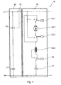
- FIG. 3 shows a circuit 40 for controlling a washing machine according to the present invention with a motor circuit 20 and a door lock circuit 30, wherein both circuits 20 and 30 are energized via a single common electronic switching element 41, such as a triac.
- a single common electronic switching element 41 such as a triac.
- the basic structure of the motor circuit 20 and the door lock circuit 30 corresponds to the respective structure as it is for FIG. 1 has been described. On the description too FIG. 1 is therefore referred to.
- an interconnection of the two relays 23.1 and 23.2 with the winding of the washing motor 22.2 generating the field would also be possible.
- the optional further relay 24 could also be connected to the rotor winding of the washing motor 22.1.
- a relay is used only to reverse the direction of rotation and a relay is used only to interrupt the motor circuit.
- circuit 40 the door latch circuit 30 is behind the single common electronic switching element 41 with the motor circuit 20 is interconnected.
- the motor circuit 20 and the door lock circuit 30 can be energized together by activating only one triac 41 and can also be switched off together.
- the simultaneous energization of motor circuit 20 and door lock circuit 30 is also decoupled. This decoupling is done by using the relays 23.1 and 23.2 and is an outstanding feature of the present invention. Because while the door lock circuit 30 remains active, the washing motor 22 and thus the drive of the laundry drum by means of the relays 23.1 and 23.2 can be switched off. In this case, the washing machine door would remain locked, for example, for safety reasons, although the motor 22 is temporarily switched off.
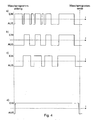
- FIG. 4 is the course of the switching state (activated - ON or OFF - OFF) of the components of the circuit 40 after FIG. 3 in the motor circuit 20 and in the door lock circuit 30 as a function of time.
- the washing program start is indicated by the first vertical line and the washing program end by the second vertical line.
- FIG. 4a refers to the switching element 41.
- the Figures 4b and 4c refer to components in the motor circuit 20.
- FIG. 4d refers to the door lock circuit 30.
- a washing program starts by t after a certain time according to FIG. 4a the common triac 41 is driven.
- the PTC bimetallic element 32 Shortly after activation of the triac 41, the PTC bimetallic element 32 reaches its operating temperature and locks the door lock as in FIG FIG. 4d shown, even beyond the end of the washing process to the end of the wash program. Only now it is again possible to open the washing machine door.
- FIG. 4b shows the drive of the laundry drum by the washing motor 22 only after some time.
- An interruption of the washing motor movement can be achieved by deactivating the triac 41 (FIG. FIG. 4a ) or by interrupting the power supply through the relays 23.1 and 23.2 ( Figure 4c ).
- first of all the motor circuit 20 (together with the door lock circuit 30) is de-energized via the triac 41 ( FIG. 4a ), in this switching state via the relays 23.1 and 23.2 ( Figure 4c ) switched the motor state and then switched on the triac 41, the current flow again ( FIG. 4a ). Consequently, the "switching spark" at the triac 41, but not at the contacts of the relays 23.1 and 23.2.
- the door latch remains open until the end of the wash cycle (FIG. FIG. 4d ), even if the switching element 41 should be temporarily deactivated during the washing process ( FIG. 4a ).
- the triac 41 is permanently de-energized until the trailing lock releases and allows the door to open safely, since the laundry drum has stopped in the meantime.
- washing motor 22 If the washing motor 22 must remain switched off during the wash program for a long time, can be energized with the relays 23.1 and 23.2 of the door lock circuit by turning on the triac 41 during the program, without causing the engine is driven ( FIG. 4a ).
Landscapes
- Engineering & Computer Science (AREA)
- Textile Engineering (AREA)
- Control Of Washing Machine And Dryer (AREA)
- Main Body Construction Of Washing Machines And Laundry Dryers (AREA)
- Chemical Or Physical Treatment Of Fibers (AREA)
- Treatment Of Fiber Materials (AREA)
- Control Of Ac Motors In General (AREA)
Claims (5)
- Circuit de commande d'un appareil de traitement du linge, le circuit présentant une boucle (20) de courant de moteur qui présente un moteur (22) à courant alternatif et une boucle (30) de courant de verrouillage de porte,
la boucle (20) de courant de moteur et la boucle (30) de courant de verrouillage de porte pouvant être commandées par un unique élément électronique de commutation (41) commun,
caractérisé en ce que
deux commutateurs électromécaniques (23.1, 23.2) sont utilisés dans la boucle de courant de moteur, sont raccordés à l'enroulement du rotor (22.1) du moteur à courant alternatif ou à l'enroulement du champ (22.2) du moteur à courant alternatif, interrompent le boucle (20) de courant de moteur dans un premier état de commutation et ont pour effet une inversion du sens de rotation du moteur (22) à courant alternatif dans un deuxième état de commutation. - Circuit selon la revendication 1, caractérisé en ce que la boucle (30) de courant de verrouillage de porte est commutée en passage par commande de l'unique élément électronique de commutation (41) commun, la boucle (20) du courant de moteur pouvant simultanément être interrompue par au moins un commutateur électromécanique (23).
- Circuit selon l'une des revendications précédentes, caractérisé en ce que l'unique élément électronique de commutation (41) est un triac ou un tyristor.
- Circuit selon l'une des revendications précédentes, caractérisé en ce que la boucle (30) de courant de verrouillage de porte présente un commutateur (32) et/ou un mécanisme de verrouillage de la porte de l'appareil qui peut être commandé par l'élément PTC à bimétal.
- Circuit selon l'une des revendications précédentes, caractérisé en ce qu'en plus des deux commutateurs électromécaniques (23.1, 23.2) qui inversent le sens de rotation du moteur (22) à courant alternatif et qui interrompent le courant du moteur, la boucle (20) de courant de moteur présente un autre commutateur-relais électromécanique (24) qui commute le champ, le commutateur électromécanique (24) de commutation du champ étant raccordé à l'autre enroulement du moteur (22) à courant alternatif que l'enroulement qui est raccordé aux deux commutateurs électromécaniques (23.1, 23.2) qui inversent le sens de rotation du moteur ou interrompent le courant du moteur.
Priority Applications (1)
| Application Number | Priority Date | Filing Date | Title |
|---|---|---|---|
| PL06021379T PL1775366T3 (pl) | 2005-10-17 | 2006-10-12 | Układ sterowania urządzeniem pralniczym |
Applications Claiming Priority (1)
| Application Number | Priority Date | Filing Date | Title |
|---|---|---|---|
| DE200510049892 DE102005049892B3 (de) | 2005-10-17 | 2005-10-17 | Schaltung zur Ansteuerung eines Geräts zur Wäschebehandlung |
Publications (2)
| Publication Number | Publication Date |
|---|---|
| EP1775366A1 EP1775366A1 (fr) | 2007-04-18 |
| EP1775366B1 true EP1775366B1 (fr) | 2010-12-22 |
Family
ID=37607434
Family Applications (1)
| Application Number | Title | Priority Date | Filing Date |
|---|---|---|---|
| EP20060021379 Not-in-force EP1775366B1 (fr) | 2005-10-17 | 2006-10-12 | Circuit de réglage pour dispositifs de traitement de tissus |
Country Status (7)
| Country | Link |
|---|---|
| US (1) | US7420345B2 (fr) |
| EP (1) | EP1775366B1 (fr) |
| CN (1) | CN1952249B (fr) |
| AT (1) | ATE492675T1 (fr) |
| DE (2) | DE102005049892B3 (fr) |
| ES (1) | ES2356753T3 (fr) |
| PL (1) | PL1775366T3 (fr) |
Families Citing this family (8)
| Publication number | Priority date | Publication date | Assignee | Title |
|---|---|---|---|---|
| CN101688355B (zh) * | 2007-06-26 | 2012-05-23 | 阿塞里克股份有限公司 | 洗涤机/干燥机 |
| DE102007031882B4 (de) * | 2007-07-09 | 2016-07-21 | Diehl Ako Stiftung & Co. Kg | Wäschebehandlungsgerät mit Türverriegelungselement |
| ITMC20070141A1 (it) * | 2007-07-10 | 2009-01-11 | Elmarc Societa Per Azioni | Sistema e circuito elettronico di protezione del portello delle macchine lavatrici o lava-asciugatrici. |
| CN106087346B (zh) * | 2009-09-10 | 2019-08-23 | 伊利诺斯工具制品有限公司 | 具有机械门传感器的电气设备锁 |
| FR2951332B1 (fr) * | 2009-10-12 | 2016-11-11 | Fagorbrandt Sas | Circuit d'alimentation capacitive d'un appareil electrique |
| TR201007760A1 (tr) * | 2010-09-22 | 2012-04-24 | Ar�El�K Anon�M ��Rket� | Bir çamaşır makinası. |
| CN102361447B (zh) * | 2011-06-01 | 2013-04-10 | 刘德军 | 具有自锁功能的单键控制开关 |
| CN102978886B (zh) * | 2012-11-29 | 2015-04-15 | 无锡小天鹅股份有限公司 | 联锁控制装置及具有其的干衣机 |
Family Cites Families (20)
| Publication number | Priority date | Publication date | Assignee | Title |
|---|---|---|---|---|
| US3597943A (en) * | 1969-06-17 | 1971-08-10 | Braun Inc G A | Sterilized laundry system |
| US3745382A (en) * | 1972-02-18 | 1973-07-10 | Rhomega Syst Inc | Solid state timer circuit for controlling the energization time of a load |
| IT994158B (it) * | 1973-08-21 | 1975-10-20 | Texas Instruments Italia Spa | Dispositivo di bloccaggio con interruttore ritardatore termico ad azionamento voltmetrico per sportelli |
| US4074545A (en) * | 1976-08-26 | 1978-02-21 | Franklin Manufacturing Company | Bimetal lid lock |
| US4120013A (en) * | 1977-03-28 | 1978-10-10 | Ametek, Inc. | Laundry machine control system |
| US4194182A (en) * | 1977-08-23 | 1980-03-18 | Martin James L | Electrical switch controllable alternatively by an internal timer and by digital information from a remote source |
| US4198563A (en) * | 1978-07-24 | 1980-04-15 | Elssner Egon H | Photodetector timer network |
| US4344000A (en) * | 1979-03-21 | 1982-08-10 | Dynascan Corporation | Power circuit control programmable timer |
| US4349748A (en) * | 1979-03-21 | 1982-09-14 | Dynascan Corporation | Timer and power control system |
| GB2048314B (en) | 1979-05-14 | 1983-05-18 | Ti Domestic Appliances Ltd | Electrical machines |
| US4494012A (en) * | 1981-10-26 | 1985-01-15 | Intermatic Incorporated | Switch timer |
| US4493410A (en) * | 1982-12-27 | 1985-01-15 | The Maytag Company | Double actuation coin slide system |
| US4623179A (en) * | 1983-12-27 | 1986-11-18 | The Maytag Company | Door latch for appliance |
| DE3423004A1 (de) | 1984-06-22 | 1986-01-02 | Miele & Cie GmbH & Co, 4830 Gütersloh | Steuerungsanordnung fuer eine programmgesteuerte waschmaschine |
| US4981024A (en) * | 1989-02-03 | 1991-01-01 | Belco Equipment, Inc. | Apparatus, system, and method for dispensing laundry chemicals |
| IT1267583B1 (it) | 1994-09-13 | 1997-02-07 | Zanussi Elettrodomestici | Macchina lavabiancheria con dispositivi perfezionati di comando e controllo |
| US5655394A (en) * | 1996-03-22 | 1997-08-12 | Dirocco, Jr.; Charles J. | Security locking device for coin-operated appliance |
| DE19953633A1 (de) * | 1999-11-09 | 2001-05-10 | Diehl Ako Stiftung Gmbh & Co | Steuereinrichtung einer Waschmaschine oder eines Wäschetrockners |
| DE20008430U1 (de) * | 2000-05-10 | 2001-09-13 | Diehl AKO Stiftung GmbH & Co. KG, 88239 Wangen | Elektrische Steuereinrichtung einer Waschmaschine oder eines Wäschetrockners |
| US7036175B2 (en) * | 2002-02-19 | 2006-05-02 | Maytag Corporation | Washing machine with pay activated bulk detergent dispenser |
-
2005
- 2005-10-17 DE DE200510049892 patent/DE102005049892B3/de not_active Expired - Fee Related
-
2006
- 2006-09-21 US US11/524,689 patent/US7420345B2/en not_active Expired - Fee Related
- 2006-10-12 ES ES06021379T patent/ES2356753T3/es active Active
- 2006-10-12 DE DE200650008546 patent/DE502006008546D1/de active Active
- 2006-10-12 EP EP20060021379 patent/EP1775366B1/fr not_active Not-in-force
- 2006-10-12 AT AT06021379T patent/ATE492675T1/de active
- 2006-10-12 PL PL06021379T patent/PL1775366T3/pl unknown
- 2006-10-12 CN CN2006101321753A patent/CN1952249B/zh not_active Expired - Fee Related
Also Published As
| Publication number | Publication date |
|---|---|
| PL1775366T3 (pl) | 2011-07-29 |
| EP1775366A1 (fr) | 2007-04-18 |
| CN1952249B (zh) | 2011-04-27 |
| ES2356753T3 (es) | 2011-04-12 |
| DE502006008546D1 (de) | 2011-02-03 |
| DE102005049892B3 (de) | 2007-05-03 |
| US7420345B2 (en) | 2008-09-02 |
| CN1952249A (zh) | 2007-04-25 |
| US20070085503A1 (en) | 2007-04-19 |
| ATE492675T1 (de) | 2011-01-15 |
Similar Documents
| Publication | Publication Date | Title |
|---|---|---|
| EP2217754B1 (fr) | Circuits pour faire fonctionner un appareil électroménager | |
| EP1250749B1 (fr) | Appareil de commutation electrique | |
| DE102005049892B3 (de) | Schaltung zur Ansteuerung eines Geräts zur Wäschebehandlung | |
| DE68906970T2 (de) | Steuermittel fuer einen elektrischen universalmotor. | |
| EP2220737A1 (fr) | Circuit pour faire fonctionner un appareil électroménager | |
| DE69506345T2 (de) | Steuerungsvorrichtung einer Waschmaschine | |
| EP1532306A2 (fr) | Appareil electromenager | |
| DE102007031882B4 (de) | Wäschebehandlungsgerät mit Türverriegelungselement | |
| DE4414984A1 (de) | Sanftanlauf der Antriebsmotoren einer Rotorspinnmaschine | |
| DE102007058380A1 (de) | Schaltungsanordnung zum Betreiben eines Hausgeräts | |
| EP1099790B1 (fr) | Commande de lave-linge ou de sèche-linge | |
| EP0499123B1 (fr) | Procédé et circuit pour la protection contre les vitesses de rotation trop élevées d'un moteur dans des appareils à pilotage électronique, en particulier des machines à laver domestiques | |
| DE3121500A1 (de) | Tuersicherung fuer eine waschmaschine, insbesondere gewerbliche waschmaschine | |
| CH660204A5 (de) | Verfahren zum ansteuern des motors einer webmaschine. | |
| EP2020721A2 (fr) | Dispositif de commutation destiné à la surveillance d'un tachymètre pour un moteur d'entraînement d'un tambour d'un lave-linge | |
| EP1962011B1 (fr) | Appareil de traitement du linge | |
| DE1585853C3 (de) | Anordnung zur elektrischen Verriegelung der Antriebsmotoren einer Waschmaschine | |
| DE724924C (de) | Einrichtung zur Verhuetung unbefugter Eingriffe in die betriebsmaessige Drehzahlregelung von Spinn- und Zwirnmaschinen mit Fadenzugreglern (Spinnreglern) | |
| EP0362495B1 (fr) | Circuit de commande pour un moteur universel | |
| EP3488042B1 (fr) | Circuit de surveillance de porte pour un appareil électroménager | |
| DE102006036956B4 (de) | Steuereinheit für einen elektrischen Antriebsmotor | |
| DE2166554A1 (de) | Programmsteuerung | |
| DE20008430U1 (de) | Elektrische Steuereinrichtung einer Waschmaschine oder eines Wäschetrockners | |
| EP0311776A2 (fr) | Circuit de protection pour la limitation de la vitesse de rotation d'un moteur d'une machine à laver | |
| CH691100A5 (de) | Verfahren zur Überwachung eines Drehstrommotors sowie Überwachungseinrichtung. |
Legal Events
| Date | Code | Title | Description |
|---|---|---|---|
| PUAI | Public reference made under article 153(3) epc to a published international application that has entered the european phase |
Free format text: ORIGINAL CODE: 0009012 |
|
| AK | Designated contracting states |
Kind code of ref document: A1 Designated state(s): AT BE BG CH CY CZ DE DK EE ES FI FR GB GR HU IE IS IT LI LT LU LV MC NL PL PT RO SE SI SK TR |
|
| AX | Request for extension of the european patent |
Extension state: AL BA HR MK YU |
|
| 17P | Request for examination filed |
Effective date: 20070512 |
|
| 17Q | First examination report despatched |
Effective date: 20070619 |
|
| AKX | Designation fees paid |
Designated state(s): AT BE BG CH CY CZ DE DK EE ES FI FR GB GR HU IE IS IT LI LT LU LV MC NL PL PT RO SE SI SK TR |
|
| GRAP | Despatch of communication of intention to grant a patent |
Free format text: ORIGINAL CODE: EPIDOSNIGR1 |
|
| GRAS | Grant fee paid |
Free format text: ORIGINAL CODE: EPIDOSNIGR3 |
|
| GRAA | (expected) grant |
Free format text: ORIGINAL CODE: 0009210 |
|
| AK | Designated contracting states |
Kind code of ref document: B1 Designated state(s): AT BE BG CH CY CZ DE DK EE ES FI FR GB GR HU IE IS IT LI LT LU LV MC NL PL PT RO SE SI SK TR |
|
| REG | Reference to a national code |
Ref country code: GB Ref legal event code: FG4D Free format text: NOT ENGLISH |
|
| REG | Reference to a national code |
Ref country code: CH Ref legal event code: EP |
|
| REG | Reference to a national code |
Ref country code: IE Ref legal event code: FG4D |
|
| REF | Corresponds to: |
Ref document number: 502006008546 Country of ref document: DE Date of ref document: 20110203 Kind code of ref document: P |
|
| REG | Reference to a national code |
Ref country code: DE Ref legal event code: R096 Ref document number: 502006008546 Country of ref document: DE Effective date: 20110203 |
|
| REG | Reference to a national code |
Ref country code: ES Ref legal event code: FG2A Ref document number: 2356753 Country of ref document: ES Kind code of ref document: T3 Effective date: 20110412 |
|
| REG | Reference to a national code |
Ref country code: NL Ref legal event code: VDEP Effective date: 20101222 |
|
| PG25 | Lapsed in a contracting state [announced via postgrant information from national office to epo] |
Ref country code: LT Free format text: LAPSE BECAUSE OF FAILURE TO SUBMIT A TRANSLATION OF THE DESCRIPTION OR TO PAY THE FEE WITHIN THE PRESCRIBED TIME-LIMIT Effective date: 20101222 |
|
| LTIE | Lt: invalidation of european patent or patent extension |
Effective date: 20101222 |
|
| PG25 | Lapsed in a contracting state [announced via postgrant information from national office to epo] |
Ref country code: FI Free format text: LAPSE BECAUSE OF FAILURE TO SUBMIT A TRANSLATION OF THE DESCRIPTION OR TO PAY THE FEE WITHIN THE PRESCRIBED TIME-LIMIT Effective date: 20101222 Ref country code: SE Free format text: LAPSE BECAUSE OF FAILURE TO SUBMIT A TRANSLATION OF THE DESCRIPTION OR TO PAY THE FEE WITHIN THE PRESCRIBED TIME-LIMIT Effective date: 20101222 Ref country code: LV Free format text: LAPSE BECAUSE OF FAILURE TO SUBMIT A TRANSLATION OF THE DESCRIPTION OR TO PAY THE FEE WITHIN THE PRESCRIBED TIME-LIMIT Effective date: 20101222 Ref country code: BG Free format text: LAPSE BECAUSE OF FAILURE TO SUBMIT A TRANSLATION OF THE DESCRIPTION OR TO PAY THE FEE WITHIN THE PRESCRIBED TIME-LIMIT Effective date: 20110322 Ref country code: CY Free format text: LAPSE BECAUSE OF FAILURE TO SUBMIT A TRANSLATION OF THE DESCRIPTION OR TO PAY THE FEE WITHIN THE PRESCRIBED TIME-LIMIT Effective date: 20101222 Ref country code: SI Free format text: LAPSE BECAUSE OF FAILURE TO SUBMIT A TRANSLATION OF THE DESCRIPTION OR TO PAY THE FEE WITHIN THE PRESCRIBED TIME-LIMIT Effective date: 20101222 |
|
| REG | Reference to a national code |
Ref country code: IE Ref legal event code: FD4D |
|
| PG25 | Lapsed in a contracting state [announced via postgrant information from national office to epo] |
Ref country code: GR Free format text: LAPSE BECAUSE OF FAILURE TO SUBMIT A TRANSLATION OF THE DESCRIPTION OR TO PAY THE FEE WITHIN THE PRESCRIBED TIME-LIMIT Effective date: 20110323 Ref country code: EE Free format text: LAPSE BECAUSE OF FAILURE TO SUBMIT A TRANSLATION OF THE DESCRIPTION OR TO PAY THE FEE WITHIN THE PRESCRIBED TIME-LIMIT Effective date: 20101222 Ref country code: IS Free format text: LAPSE BECAUSE OF FAILURE TO SUBMIT A TRANSLATION OF THE DESCRIPTION OR TO PAY THE FEE WITHIN THE PRESCRIBED TIME-LIMIT Effective date: 20110422 Ref country code: CZ Free format text: LAPSE BECAUSE OF FAILURE TO SUBMIT A TRANSLATION OF THE DESCRIPTION OR TO PAY THE FEE WITHIN THE PRESCRIBED TIME-LIMIT Effective date: 20101222 Ref country code: PT Free format text: LAPSE BECAUSE OF FAILURE TO SUBMIT A TRANSLATION OF THE DESCRIPTION OR TO PAY THE FEE WITHIN THE PRESCRIBED TIME-LIMIT Effective date: 20110422 |
|
| REG | Reference to a national code |
Ref country code: PL Ref legal event code: T3 |
|
| PG25 | Lapsed in a contracting state [announced via postgrant information from national office to epo] |
Ref country code: SK Free format text: LAPSE BECAUSE OF FAILURE TO SUBMIT A TRANSLATION OF THE DESCRIPTION OR TO PAY THE FEE WITHIN THE PRESCRIBED TIME-LIMIT Effective date: 20101222 Ref country code: NL Free format text: LAPSE BECAUSE OF FAILURE TO SUBMIT A TRANSLATION OF THE DESCRIPTION OR TO PAY THE FEE WITHIN THE PRESCRIBED TIME-LIMIT Effective date: 20101222 Ref country code: RO Free format text: LAPSE BECAUSE OF FAILURE TO SUBMIT A TRANSLATION OF THE DESCRIPTION OR TO PAY THE FEE WITHIN THE PRESCRIBED TIME-LIMIT Effective date: 20101222 |
|
| PLBE | No opposition filed within time limit |
Free format text: ORIGINAL CODE: 0009261 |
|
| STAA | Information on the status of an ep patent application or granted ep patent |
Free format text: STATUS: NO OPPOSITION FILED WITHIN TIME LIMIT |
|
| PG25 | Lapsed in a contracting state [announced via postgrant information from national office to epo] |
Ref country code: DK Free format text: LAPSE BECAUSE OF FAILURE TO SUBMIT A TRANSLATION OF THE DESCRIPTION OR TO PAY THE FEE WITHIN THE PRESCRIBED TIME-LIMIT Effective date: 20101222 Ref country code: IE Free format text: LAPSE BECAUSE OF FAILURE TO SUBMIT A TRANSLATION OF THE DESCRIPTION OR TO PAY THE FEE WITHIN THE PRESCRIBED TIME-LIMIT Effective date: 20101222 |
|
| 26N | No opposition filed |
Effective date: 20110923 |
|
| REG | Reference to a national code |
Ref country code: DE Ref legal event code: R097 Ref document number: 502006008546 Country of ref document: DE Effective date: 20110923 |
|
| BERE | Be: lapsed |
Owner name: DIEHL AKO STIFTUNG & CO. K.G. Effective date: 20111031 |
|
| PG25 | Lapsed in a contracting state [announced via postgrant information from national office to epo] |
Ref country code: MC Free format text: LAPSE BECAUSE OF NON-PAYMENT OF DUE FEES Effective date: 20111031 |
|
| REG | Reference to a national code |
Ref country code: CH Ref legal event code: PL |
|
| GBPC | Gb: european patent ceased through non-payment of renewal fee |
Effective date: 20111012 |
|
| PG25 | Lapsed in a contracting state [announced via postgrant information from national office to epo] |
Ref country code: LI Free format text: LAPSE BECAUSE OF NON-PAYMENT OF DUE FEES Effective date: 20111031 Ref country code: BE Free format text: LAPSE BECAUSE OF NON-PAYMENT OF DUE FEES Effective date: 20111031 Ref country code: CH Free format text: LAPSE BECAUSE OF NON-PAYMENT OF DUE FEES Effective date: 20111031 |
|
| PG25 | Lapsed in a contracting state [announced via postgrant information from national office to epo] |
Ref country code: GB Free format text: LAPSE BECAUSE OF NON-PAYMENT OF DUE FEES Effective date: 20111012 |
|
| REG | Reference to a national code |
Ref country code: AT Ref legal event code: MM01 Ref document number: 492675 Country of ref document: AT Kind code of ref document: T Effective date: 20111012 |
|
| PG25 | Lapsed in a contracting state [announced via postgrant information from national office to epo] |
Ref country code: AT Free format text: LAPSE BECAUSE OF NON-PAYMENT OF DUE FEES Effective date: 20111012 |
|
| PG25 | Lapsed in a contracting state [announced via postgrant information from national office to epo] |
Ref country code: LU Free format text: LAPSE BECAUSE OF NON-PAYMENT OF DUE FEES Effective date: 20111012 |
|
| PG25 | Lapsed in a contracting state [announced via postgrant information from national office to epo] |
Ref country code: TR Free format text: LAPSE BECAUSE OF FAILURE TO SUBMIT A TRANSLATION OF THE DESCRIPTION OR TO PAY THE FEE WITHIN THE PRESCRIBED TIME-LIMIT Effective date: 20101222 |
|
| PG25 | Lapsed in a contracting state [announced via postgrant information from national office to epo] |
Ref country code: HU Free format text: LAPSE BECAUSE OF FAILURE TO SUBMIT A TRANSLATION OF THE DESCRIPTION OR TO PAY THE FEE WITHIN THE PRESCRIBED TIME-LIMIT Effective date: 20101222 |
|
| REG | Reference to a national code |
Ref country code: FR Ref legal event code: PLFP Year of fee payment: 10 |
|
| PGFP | Annual fee paid to national office [announced via postgrant information from national office to epo] |
Ref country code: IT Payment date: 20151028 Year of fee payment: 10 |
|
| PGFP | Annual fee paid to national office [announced via postgrant information from national office to epo] |
Ref country code: FR Payment date: 20151023 Year of fee payment: 10 Ref country code: ES Payment date: 20151028 Year of fee payment: 10 |
|
| REG | Reference to a national code |
Ref country code: FR Ref legal event code: ST Effective date: 20170630 |
|
| PG25 | Lapsed in a contracting state [announced via postgrant information from national office to epo] |
Ref country code: FR Free format text: LAPSE BECAUSE OF NON-PAYMENT OF DUE FEES Effective date: 20161102 |
|
| PG25 | Lapsed in a contracting state [announced via postgrant information from national office to epo] |
Ref country code: IT Free format text: LAPSE BECAUSE OF NON-PAYMENT OF DUE FEES Effective date: 20161012 |
|
| PGFP | Annual fee paid to national office [announced via postgrant information from national office to epo] |
Ref country code: DE Payment date: 20171212 Year of fee payment: 12 |
|
| PG25 | Lapsed in a contracting state [announced via postgrant information from national office to epo] |
Ref country code: ES Free format text: LAPSE BECAUSE OF NON-PAYMENT OF DUE FEES Effective date: 20161013 |
|
| REG | Reference to a national code |
Ref country code: ES Ref legal event code: FD2A Effective date: 20181128 |
|
| PGFP | Annual fee paid to national office [announced via postgrant information from national office to epo] |
Ref country code: PL Payment date: 20180924 Year of fee payment: 13 |
|
| REG | Reference to a national code |
Ref country code: DE Ref legal event code: R119 Ref document number: 502006008546 Country of ref document: DE |
|
| PG25 | Lapsed in a contracting state [announced via postgrant information from national office to epo] |
Ref country code: DE Free format text: LAPSE BECAUSE OF NON-PAYMENT OF DUE FEES Effective date: 20190501 |
|
| PG25 | Lapsed in a contracting state [announced via postgrant information from national office to epo] |
Ref country code: PL Free format text: LAPSE BECAUSE OF NON-PAYMENT OF DUE FEES Effective date: 20191012 |