EP2020721A2 - Dispositif de commutation destiné à la surveillance d'un tachymètre pour un moteur d'entraînement d'un tambour d'un lave-linge - Google Patents
Dispositif de commutation destiné à la surveillance d'un tachymètre pour un moteur d'entraînement d'un tambour d'un lave-linge Download PDFInfo
- Publication number
- EP2020721A2 EP2020721A2 EP08104822A EP08104822A EP2020721A2 EP 2020721 A2 EP2020721 A2 EP 2020721A2 EP 08104822 A EP08104822 A EP 08104822A EP 08104822 A EP08104822 A EP 08104822A EP 2020721 A2 EP2020721 A2 EP 2020721A2
- Authority
- EP
- European Patent Office
- Prior art keywords
- circuit arrangement
- arrangement according
- tachometer
- motor
- switching element
- Prior art date
- Legal status (The legal status is an assumption and is not a legal conclusion. Google has not performed a legal analysis and makes no representation as to the accuracy of the status listed.)
- Granted
Links
Images


Classifications
-
- H—ELECTRICITY
- H02—GENERATION; CONVERSION OR DISTRIBUTION OF ELECTRIC POWER
- H02H—EMERGENCY PROTECTIVE CIRCUIT ARRANGEMENTS
- H02H7/00—Emergency protective circuit arrangements specially adapted for specific types of electric machines or apparatus or for sectionalised protection of cable or line systems, and effecting automatic switching in the event of an undesired change from normal working conditions
- H02H7/08—Emergency protective circuit arrangements specially adapted for specific types of electric machines or apparatus or for sectionalised protection of cable or line systems, and effecting automatic switching in the event of an undesired change from normal working conditions for dynamo-electric motors
- H02H7/0833—Emergency protective circuit arrangements specially adapted for specific types of electric machines or apparatus or for sectionalised protection of cable or line systems, and effecting automatic switching in the event of an undesired change from normal working conditions for dynamo-electric motors for electric motors with control arrangements
-
- D—TEXTILES; PAPER
- D06—TREATMENT OF TEXTILES OR THE LIKE; LAUNDERING; FLEXIBLE MATERIALS NOT OTHERWISE PROVIDED FOR
- D06F—LAUNDERING, DRYING, IRONING, PRESSING OR FOLDING TEXTILE ARTICLES
- D06F37/00—Details specific to washing machines covered by groups D06F21/00 - D06F25/00
- D06F37/30—Driving arrangements
-
- D—TEXTILES; PAPER
- D06—TREATMENT OF TEXTILES OR THE LIKE; LAUNDERING; FLEXIBLE MATERIALS NOT OTHERWISE PROVIDED FOR
- D06F—LAUNDERING, DRYING, IRONING, PRESSING OR FOLDING TEXTILE ARTICLES
- D06F37/00—Details specific to washing machines covered by groups D06F21/00 - D06F25/00
- D06F37/30—Driving arrangements
- D06F37/304—Arrangements or adaptations of electric motors
-
- D—TEXTILES; PAPER
- D06—TREATMENT OF TEXTILES OR THE LIKE; LAUNDERING; FLEXIBLE MATERIALS NOT OTHERWISE PROVIDED FOR
- D06F—LAUNDERING, DRYING, IRONING, PRESSING OR FOLDING TEXTILE ARTICLES
- D06F2103/00—Parameters monitored or detected for the control of domestic laundry washing machines, washer-dryers or laundry dryers
- D06F2103/44—Current or voltage
- D06F2103/46—Current or voltage of the motor driving the drum
-
- D—TEXTILES; PAPER
- D06—TREATMENT OF TEXTILES OR THE LIKE; LAUNDERING; FLEXIBLE MATERIALS NOT OTHERWISE PROVIDED FOR
- D06F—LAUNDERING, DRYING, IRONING, PRESSING OR FOLDING TEXTILE ARTICLES
- D06F34/00—Details of control systems for washing machines, washer-dryers or laundry dryers
- D06F34/08—Control circuits or arrangements thereof
-
- Y—GENERAL TAGGING OF NEW TECHNOLOGICAL DEVELOPMENTS; GENERAL TAGGING OF CROSS-SECTIONAL TECHNOLOGIES SPANNING OVER SEVERAL SECTIONS OF THE IPC; TECHNICAL SUBJECTS COVERED BY FORMER USPC CROSS-REFERENCE ART COLLECTIONS [XRACs] AND DIGESTS
- Y02—TECHNOLOGIES OR APPLICATIONS FOR MITIGATION OR ADAPTATION AGAINST CLIMATE CHANGE
- Y02B—CLIMATE CHANGE MITIGATION TECHNOLOGIES RELATED TO BUILDINGS, e.g. HOUSING, HOUSE APPLIANCES OR RELATED END-USER APPLICATIONS
- Y02B40/00—Technologies aiming at improving the efficiency of home appliances, e.g. induction cooking or efficient technologies for refrigerators, freezers or dish washers
Definitions
- the invention relates to a circuit arrangement for monitoring a tachometer, with which a speed of a motor can be detected, which has control electronics, by means of which the speed of the motor is controllable by a motor electrically connected to the first electronic switching element.
- a monitoring circuit for the control of an electric motor in particular a laundry drum motor, known.
- Circuit-technical fault conditions such as the short circuit of a first electronic switching element designed as triac and / or a tachogenite, are to be detected by means of the monitoring circuit.
- Parallel to the series connection of the motor and a switch, a parallel resistor is connected, which is connected in series with the triac for the motor.
- the voltage states resulting in the normal case and in the event of a fault are detected by control electronics, in particular a microprocessor, which regulates the engine speed.
- a circuit arrangement for monitoring a tachometer, with which the rotational speed of a motor can be detected comprises control electronics, by means of which the rotational speed of the motor can be regulated by a first electronic switching element electrically connected to the motor.
- the control electronics are connected to a tachometer evaluation circuit, which has a second electronic switching element which comprises a control electrode.
- the control electrode of the second electronic switching element is biased and thus acted upon by an offset voltage.
- the bias of the control electrode of the second electronic switching element is set so that with a comparison without biasing the control electrode lower electrical voltage is sufficient to enable the second switching element in the conductive state.
- it is thus only necessary to overcome a smaller voltage interval in order to set the conductive state of the second switching element, which can also be done in a shortened time, whereby the early detection of malfunction of the tachometer is possible.
- control electrode of the second switching element is electrically connected to a second circuit node, with which an inductance of the tachometer and a current source, with which the bias of the control electrode is generated, are electrically connected.
- the bias voltage of the control electrode can be set particularly easily.
- the current source comprises a resistor and a diode connected in series therewith.
- the diode can also be designed as a Zener diode. Mainly, the diode performs a protective function and can be dispensed with appropriate dimensioning of the resistor. But to protect against interference on the supply voltage line, it is advantageous in any case.
- the bias voltage of the control electrode of the second electronic switching element between 0.1 V and 0.4 V.
- the bias voltage is a value of about 0.2 V.
- control electronics comprises a microprocessor which is connected to the second electronic switching element and depending on the Operating state of the second switching element, an associated state of a digital signal is applied to the microprocessor, wherein depending on the state of the digital signal, a malfunction of the tachometer is recognizable.
- the microprocessor is electrically connected to a working electrode of the second electronic switching element.
- the tachometer device preferably comprises an induction coil and a magnetic pole wheel.
- the tachometer is preferably designed so that it generates an alternating voltage signal during operation of the motor.
- the conductive state of the second electronic switching element can be generated by the positive half cycle of this alternating voltage signal and for the duration of the positive half cycle, a first state, in particular the "low" state of the digital signal is applied to the input of the microprocessor.
- the second electronic switching element is preferably disabled during the period of the negative half cycle of the AC signal.
- the negative half-wave of the AC signal generated by the tachometer device during operation of the motor is limited in particular to an electrical voltage to a value of minus 0.7 V.
- a second state, in particular the "high" state of the digital signal is applied to the input of the microprocessor for the duration of the negative half-wave.
- the diode of the current source is preferably blocked during the period of the positive half cycle of the AC signal when applied to it a voltage greater than 4.2 V, in particular greater than 4.4 V.
- the diode of the current source is preferably conductive during the period of the negative half cycle of the AC signal.
- the second electronic switching element is designed in particular as a transistor. This includes not only a control electrode and a working electrode but also a reference electrode. These are formed in one embodiment as a bipolar transistor as a base, emitter and collector.
- any other transistor type can also be provided for the second electronic switching element.
- the motor for driving a drum for a household appliance for the care of laundry in particular a washing machine, a washer-dryer or a tumble dryer is formed.
- Another aspect of the invention relates to a domestic appliance for the care of laundry items, in particular a washing machine, a tumble dryer or a washer-dryer, with a drum for receiving laundry items and a motor for driving the drum.
- the domestic appliance further comprises a circuit arrangement according to the invention or an advantageous embodiment thereof, which is designed to monitor the operation of a tachometer device of an engine.
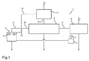
- Fig. 1 is shown in a schematic block diagram of a circuit arrangement 1, which is designed to monitor a tachometer 2.
- the circuit arrangement 1 is arranged in the exemplary embodiment in a household appliance for the care of laundry items, wherein the tachometer 2 comprises an induction coil 3 and a magnetic flywheel 4.
- a motor 5 which is designed as a universal motor and is provided for driving a drum, not shown, of the domestic appliance.
- the control of the motor 5 is effected by one of the control electronics of the circuit 1 associated microprocessor 6, wherein this is done via a phase control via a triac 7, which is designed as a first electronic switching element.
- the speed of the motor 5 For controlling the speed of the motor 5, the speed of the motor 5 must be known. This speed is detected by the tachometer 2, processed in a tachometer evaluation circuit 8 and applied to the microprocessor 6 in particular at its timer input.
- the tachometer evaluation circuit 8 is connected to the microprocessor 6 via a signal connection 9. Furthermore, the tacho-evaluation circuit 8 is connected via a signal connection 10 to a circuit node 12, wherein the tachometer 2 is connected via a signal connection 11 with this circuit node 12.
- Both the tachometer 2, as well as the tachometer evaluation circuit 8 and the microprocessor 6 are also connected to ground potential. The same applies to the engine 5.
- the circuit arrangement 1 furthermore comprises a current source 13 which, like the micro processor 6, is wound with supply voltage potential V N. Furthermore, it can be provided that the current source 13 is connected directly to the tacho-evaluation circuit 8 via a signal connection 14. Alternatively, it can be provided that the current source 13 is connected to the circuit node 12 via a signal connection 15.
- the tachometer 2 provides during operation of the motor 5, an AC signal whose amplitude and frequency are dependent on the engine speed.
- the tacho-evaluation circuit 8 converts the AC voltage into a digital signal which can be utilized by the microprocessor 6. If now the coil 3 of the speedometer device 2 is damaged and, in particular, there is a tachogenite, a regulation of the engine speed due to the absence of tacho pulses can no longer take place. A Tachobrucherkennung then takes place in such a way that during the controlled soft start of the motor 5, a check for tachometer pulses is performed. If no tacho pulses are detected during the controlled soft start of the motor 5, there is a suspicion of a speedometer error. Thereupon, by switching off the reversing relay a shutdown of the motor circuit is performed. After a certain period of time, which represents the recovery time of the speedometer device, the inverter relays are switched on again and it is a renewed attempt to control the motor 5. If then a tacho error is detected continuously in sequence, then the safe state is taken.
- the current source 13 is provided.
- a bias voltage of a second electronic switching element of the tacho-evaluation circuit 8 can be achieved.
- Fig. 2 a circuit diagram is shown, which the circuit 1 in Fig. 1 shows in more detail.
- the tachometer 2 comprises, in addition to the coil 3, a resistor 30 connected in series therewith.
- the current source 13 comprises an ohmic resistor 16, which is connected in series with a diode 17.
- the diode 17 may also be formed as a Zener diode.
- the tacho evaluation circuit 8 comprises a first capacitor 18 which is connected directly to the circuit node 12 on the one hand and ground potential on the other hand. Furthermore, the tacho evaluation circuit 8 is associated with a diode 19, which is connected to a circuit node 28 on the one hand and ground potential on the other. This diode 19 may also be formed as a Zener diode.
- the tacho evaluation circuit 8 comprises a further capacitor 21 and an ohmic resistor 22 connected to a circuit node 31.
- the tacho evaluation circuit 8 comprises a second electronic switching element, which is designed as a transistor 23 in the embodiment.
- the control electrode 24 of the transistor 23 is connected to a circuit branch which is contacted with the circuit node 12.
- an ohmic resistor 20 is arranged in this circuit branch extending between the circuit node 12 and the control electrode 24, an ohmic resistor 20 is arranged.
- the transistor 23 further includes a reference electrode 25 and a working electrode 26. Die in Fig. 2 shown embodiment of the transistor 23 is merely exemplary and there may be provided any type of transistor for the second electronic switching element.
- the working electrode 26 is connected to the supply voltage potential V N via a further resistor 29.
- the provision of the voltage to the microprocessor 6 can be ensured via the capacitor 27.
- the line between the working electrode 26 and the microprocessor 6 may include, in addition to the capacitor 27, an additional resistor (not shown), which additional resistor may be wholly or partially in an input impedance of the microprocessor.
- This additional resistor and capacitor 27 form an RC filter which may be useful for smoothing the signal applied to the microprocessor.
- a corresponding coupling is provided, as is indicated schematically by the direct connection line between the two components 2 and 5.
- the transistor 23 locks in this state still safe.
- a permanent "high" signal of about + 5V is output.
- the tachometer 2 is functional and the motor 5 can be controlled.
- the tachometer 2 of the motor 5 In a state in which the motor 5 rotates and only the tachometer 2 is functioning properly, the tachometer 2 of the motor 5 generates an AC signal when the motor rotates.
- the positive half wave of this AC signal is through the voltage divider comprising the resistors 16, 20 and 22 are applied to the control electrode 24 of the transistor 23 and the transistor 23 is turned on.
- the voltage across the diode 17 can drop so far that the diode blocks and thereby turns off the resistor 16 from the voltage divider 16, 20 and 22; the signal reaching transistor 23 is then only determined by resistors 20 and 22.
- the transistor 23 Due to the bias voltage applied to the control electrode 24 offset voltage, which is generated due to the wiring via the current source 13, dimensioned with a value of about 0.2 V. By this bias, the transistor 23 can be controlled faster or earlier or with a lower voltage than would be the case without the current source.
- the negative half-wave of the AC signal of the tachometer 2 is limited via the resistors 16 and 30 and the diode 19 to minus 0.7 V at the circuit node 12, so that the transistor 23 is disabled during the time of the negative half-wave.
- a "high" signal is set for this period of the negative half wave.
- the diode 17 of the current source 13 is blocking if at its cathode, a voltage greater than about 4.4 V is applied. At the negative half-wave of the AC signal, this diode 17 is conductive. Via the diode 19, the potential at the cathode of the diode 17 is limited to minus 0.7V.
- a reliable detection of a tacho break can be achieved by evaluating a digital signal.
- the detection of a possible tacho break can be ensured even before the test of the turning relay, the test of the triac 7 and in particular before the control of the motor 5.
- the safe state can immediately after detection of a Tacho error be taken.
- improved sensitivity can be ensured at low engine speeds, and smaller engine speeds than the conventional approach can be recognized.
- the voltage supply of the circuit arrangement 1 can also be different.
- An essential aspect is in particular the bias of the control electrode 24 of the transistor 23, which can be achieved in particular by the current source 13 to the resistor 16 and the diode 17 connected in series in conjunction with the resistors 20 and 22.
- Fig. 3 two waveforms are shown, wherein in the upper diagram, a waveform at the coil 3 of the tachometer 2 is shown, when the circuit arrangement 1, the current source 13 does not include.
- the lower diagram shows a signal curve at the input of the microprocessor 6, when the circuit arrangement 1 does not include the current source 13.
- Fig. 3 can be seen that in the time phase t from 0 s to 80 ms no tacho signal is present.
- the speedometer is functional.
- At the microprocessor 6 is in accordance with the waveform in the lower diagram to a "high" - signal.
- a tacho signal is present in the upper diagram according to the signal curve.
- a digital signal which has a relatively short pause duration.
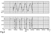
- a waveform is shown at the input of the microprocessor 6, as in a circuit arrangement 1 with the current source 13 according to the embodiment in Fig. 2 occurs.
- time phase t between 0 and 80 ms is in accordance with the upper diagram in Fig. 4 no speedometer signal available.
- the tachometer 2 is functional and the microprocessor 6 is according to the lower diagram in this time phase, a "high" - signal.
- a speedometer signal available.
- a digital signal which is a longer pause duration compared to the microprocessor signal in Fig. 3 in the time phase between 80 ms and 250 ms.
Landscapes
- Engineering & Computer Science (AREA)
- Textile Engineering (AREA)
- Control Of Ac Motors In General (AREA)
- Control Of Washing Machine And Dryer (AREA)
Priority Applications (1)
| Application Number | Priority Date | Filing Date | Title |
|---|---|---|---|
| PL08104822T PL2020721T3 (pl) | 2007-08-03 | 2008-07-22 | Układ przełączający do monitorowania urządzenia tachometrycznego dla silnika napędowego bębna pralki |
Applications Claiming Priority (1)
| Application Number | Priority Date | Filing Date | Title |
|---|---|---|---|
| DE102007036668A DE102007036668A1 (de) | 2007-08-03 | 2007-08-03 | Schaltungsanordnung zur Überwachung einer Tachoeinrichtung für einen Antriebsmotor einer Trommel einer Waschmaschine |
Publications (3)
| Publication Number | Publication Date |
|---|---|
| EP2020721A2 true EP2020721A2 (fr) | 2009-02-04 |
| EP2020721A3 EP2020721A3 (fr) | 2012-06-27 |
| EP2020721B1 EP2020721B1 (fr) | 2013-05-22 |
Family
ID=39968143
Family Applications (1)
| Application Number | Title | Priority Date | Filing Date |
|---|---|---|---|
| EP08104822.5A Active EP2020721B1 (fr) | 2007-08-03 | 2008-07-22 | Dispositif de commutation destiné à la surveillance d'un tachymètre pour un moteur d'entraînement d'un tambour d'un lave-linge |
Country Status (3)
| Country | Link |
|---|---|
| EP (1) | EP2020721B1 (fr) |
| DE (1) | DE102007036668A1 (fr) |
| PL (1) | PL2020721T3 (fr) |
Cited By (2)
| Publication number | Priority date | Publication date | Assignee | Title |
|---|---|---|---|---|
| WO2012049109A1 (fr) * | 2010-10-11 | 2012-04-19 | BSH Bosch und Siemens Hausgeräte GmbH | Procédé pour faire fonctionner un appareil électroménager comprenant un commutateur à semi-conducteur et une unité de commande pour contrôler le fonctionnement du commutateur électrique à semi-conducteur, et appareil électroménager |
| EP2770101A1 (fr) * | 2013-02-22 | 2014-08-27 | Electrolux Home Products Corporation N.V. | Machine de blanchisserie |
Families Citing this family (1)
| Publication number | Priority date | Publication date | Assignee | Title |
|---|---|---|---|---|
| DE102011078923A1 (de) * | 2011-07-11 | 2013-01-17 | BSH Bosch und Siemens Hausgeräte GmbH | Verfahren zum Regeln der Drehzahl eines elektrischen Antriebsmotors eines Haushaltsgeräts und Haushaltsgerät |
Citations (1)
| Publication number | Priority date | Publication date | Assignee | Title |
|---|---|---|---|---|
| DE19733533A1 (de) | 1997-08-02 | 1999-02-04 | Ako Werke Gmbh & Co | Überwachungsschaltung für die Steuerung eines Elektromotors, insbesondere Wäschetrommelmotors |
Family Cites Families (3)
| Publication number | Priority date | Publication date | Assignee | Title |
|---|---|---|---|---|
| DE2049995A1 (de) * | 1970-10-12 | 1972-05-18 | Lestra Ag | Anordnung zur Drehzahlmessung |
| GB1450679A (en) * | 1972-11-27 | 1976-09-22 | Hotpoint Ltd | Clothes washing and spin drying machines |
| DE2515792B2 (de) * | 1975-04-11 | 1978-02-09 | Zusatz in: 25 26 963 Licentia Patent-Verwaltungs-GmbH | Anordnung zur drehzahlregelung fuer einen gleichstrom-reihenschlussmotor zum antrieb einer waschmaschine |
-
2007
- 2007-08-03 DE DE102007036668A patent/DE102007036668A1/de not_active Ceased
-
2008
- 2008-07-22 PL PL08104822T patent/PL2020721T3/pl unknown
- 2008-07-22 EP EP08104822.5A patent/EP2020721B1/fr active Active
Patent Citations (1)
| Publication number | Priority date | Publication date | Assignee | Title |
|---|---|---|---|---|
| DE19733533A1 (de) | 1997-08-02 | 1999-02-04 | Ako Werke Gmbh & Co | Überwachungsschaltung für die Steuerung eines Elektromotors, insbesondere Wäschetrommelmotors |
Cited By (3)
| Publication number | Priority date | Publication date | Assignee | Title |
|---|---|---|---|---|
| WO2012049109A1 (fr) * | 2010-10-11 | 2012-04-19 | BSH Bosch und Siemens Hausgeräte GmbH | Procédé pour faire fonctionner un appareil électroménager comprenant un commutateur à semi-conducteur et une unité de commande pour contrôler le fonctionnement du commutateur électrique à semi-conducteur, et appareil électroménager |
| EP2770101A1 (fr) * | 2013-02-22 | 2014-08-27 | Electrolux Home Products Corporation N.V. | Machine de blanchisserie |
| WO2014128226A1 (fr) * | 2013-02-22 | 2014-08-28 | Electrolux Home Products Corporation N.V. | Machine de blanchisserie |
Also Published As
| Publication number | Publication date |
|---|---|
| DE102007036668A1 (de) | 2009-02-19 |
| EP2020721B1 (fr) | 2013-05-22 |
| EP2020721A3 (fr) | 2012-06-27 |
| PL2020721T3 (pl) | 2013-10-31 |
Similar Documents
| Publication | Publication Date | Title |
|---|---|---|
| EP2373839B1 (fr) | Appareil electro-menager avec dispositiv d'arret automatique | |
| EP2217754B1 (fr) | Circuits pour faire fonctionner un appareil électroménager | |
| EP2085836B1 (fr) | Circuit et procédé pour faire fonctionner un appareil électroménager | |
| EP2220737B1 (fr) | Circuit pour faire fonctionner un appareil électroménager | |
| EP2020721B1 (fr) | Dispositif de commutation destiné à la surveillance d'un tachymètre pour un moteur d'entraînement d'un tambour d'un lave-linge | |
| EP2442438A2 (fr) | Dispositif de pompe pour un appareil ménager, appareil ménager et procédé de fonctionnement d'un dispositif d'entraînement | |
| EP2548038A1 (fr) | Procédé et dispositif pour la détection d'un blocage ou d'un point dur d'un moteur à courant continu | |
| DE102009010408A1 (de) | Verfahren zum Betreiben eines Elektromotors | |
| DE102005049892B3 (de) | Schaltung zur Ansteuerung eines Geräts zur Wäschebehandlung | |
| DE102015220910A1 (de) | Spannungsüberwachung für eine Motoransteuerschaltung eines bürstenlosen Waschmaschinenmotors | |
| EP2836635B1 (fr) | Circuit d'excitation de moteur sans balais pour machine à laver | |
| WO2009121854A1 (fr) | Arrangement de circuit pour faire fonctionner un appareil ménager et procédé correspondant | |
| DE102014216556B4 (de) | Schaltungsanordnung zum Steuern einer elektrisch angetriebenen Verriegelungseinrichtung für eine Tür eines Haushaltsgeräts, Haushaltsgerät sowie Verfahren hierfür | |
| DE9407983U1 (de) | Vorrichtung zum Antrieb eines Einphasen-Synchronmotors, insbesondere zum Antrieb eines Pumpenantriebes in einem Haushaltsgerät | |
| EP0456874B1 (fr) | Protection contre la surcharge d'un bobinage d'un moteur série à courant continu, surveillé par un dispositif de mesure de la vitesse de rotation | |
| DE3543213C2 (fr) | ||
| DE102008007563A1 (de) | Schaltungsanordnung zum Auswerten von Signalen einer Tachoeinrichtung | |
| WO2009098143A2 (fr) | Machine électrique excitée par aimant permanent pour un appareil électroménager et circuiterie comprenant une machine excitée par aimant permanent | |
| DE69610799T2 (de) | Verfahren und Vorrichtung zum Positionieren der Haltestellung der Trommel einer Topladerwaschmaschine | |
| DE102008016472A1 (de) | Schaltungsanordnung zum Betreiben einer elektrischen Maschine eines Hausgeräts und entsprechendes Verfahren | |
| DE102008016475A1 (de) | Schaltungsanordnung zum Betreiben von mindestens zwei elektrischen Verbrauchern eines Hausgeräts sowie entsprechendes Verfahren | |
| DE102006036956B4 (de) | Steuereinheit für einen elektrischen Antriebsmotor | |
| DE102014209113A1 (de) | Verriegelungseinrichtung zum Verriegeln einer Tür eines Haushaltsgeräts, Haushaltsgerät und entsprechendes Verfahren | |
| DE2149811C3 (de) | Schaltungsanordnung zur Steuerung eines Einphasensynchronmotors | |
| DE102016213136A1 (de) | Türüberwachungsschaltung für ein Haushaltsgerät |
Legal Events
| Date | Code | Title | Description |
|---|---|---|---|
| PUAI | Public reference made under article 153(3) epc to a published international application that has entered the european phase |
Free format text: ORIGINAL CODE: 0009012 |
|
| AK | Designated contracting states |
Kind code of ref document: A2 Designated state(s): AT BE BG CH CY CZ DE DK EE ES FI FR GB GR HR HU IE IS IT LI LT LU LV MC MT NL NO PL PT RO SE SI SK TR |
|
| AX | Request for extension of the european patent |
Extension state: AL BA MK RS |
|
| PUAL | Search report despatched |
Free format text: ORIGINAL CODE: 0009013 |
|
| AK | Designated contracting states |
Kind code of ref document: A3 Designated state(s): AT BE BG CH CY CZ DE DK EE ES FI FR GB GR HR HU IE IS IT LI LT LU LV MC MT NL NO PL PT RO SE SI SK TR |
|
| AX | Request for extension of the european patent |
Extension state: AL BA MK RS |
|
| RIC1 | Information provided on ipc code assigned before grant |
Ipc: H02H 7/08 20060101AFI20120521BHEP Ipc: D06F 37/30 20060101ALI20120521BHEP Ipc: H02P 29/02 20060101ALI20120521BHEP |
|
| GRAP | Despatch of communication of intention to grant a patent |
Free format text: ORIGINAL CODE: EPIDOSNIGR1 |
|
| 17P | Request for examination filed |
Effective date: 20130102 |
|
| AKX | Designation fees paid |
Designated state(s): AT BE BG CH CY CZ DE DK EE ES FI FR GB GR HR HU IE IS IT LI LT LU LV MC MT NL NO PL PT RO SE SI SK TR |
|
| GRAS | Grant fee paid |
Free format text: ORIGINAL CODE: EPIDOSNIGR3 |
|
| GRAA | (expected) grant |
Free format text: ORIGINAL CODE: 0009210 |
|
| AK | Designated contracting states |
Kind code of ref document: B1 Designated state(s): AT BE BG CH CY CZ DE DK EE ES FI FR GB GR HR HU IE IS IT LI LT LU LV MC MT NL NO PL PT RO SE SI SK TR |
|
| REG | Reference to a national code |
Ref country code: GB Ref legal event code: FG4D Free format text: NOT ENGLISH |
|
| REG | Reference to a national code |
Ref country code: CH Ref legal event code: EP |
|
| REG | Reference to a national code |
Ref country code: AT Ref legal event code: REF Ref document number: 613657 Country of ref document: AT Kind code of ref document: T Effective date: 20130615 |
|
| REG | Reference to a national code |
Ref country code: IE Ref legal event code: FG4D Free format text: LANGUAGE OF EP DOCUMENT: GERMAN |
|
| REG | Reference to a national code |
Ref country code: DE Ref legal event code: R096 Ref document number: 502008009969 Country of ref document: DE Effective date: 20130718 |
|
| REG | Reference to a national code |
Ref country code: LT Ref legal event code: MG4D |
|
| PG25 | Lapsed in a contracting state [announced via postgrant information from national office to epo] |
Ref country code: ES Free format text: LAPSE BECAUSE OF FAILURE TO SUBMIT A TRANSLATION OF THE DESCRIPTION OR TO PAY THE FEE WITHIN THE PRESCRIBED TIME-LIMIT Effective date: 20130902 Ref country code: FI Free format text: LAPSE BECAUSE OF FAILURE TO SUBMIT A TRANSLATION OF THE DESCRIPTION OR TO PAY THE FEE WITHIN THE PRESCRIBED TIME-LIMIT Effective date: 20130522 Ref country code: LT Free format text: LAPSE BECAUSE OF FAILURE TO SUBMIT A TRANSLATION OF THE DESCRIPTION OR TO PAY THE FEE WITHIN THE PRESCRIBED TIME-LIMIT Effective date: 20130522 Ref country code: IS Free format text: LAPSE BECAUSE OF FAILURE TO SUBMIT A TRANSLATION OF THE DESCRIPTION OR TO PAY THE FEE WITHIN THE PRESCRIBED TIME-LIMIT Effective date: 20130922 Ref country code: SI Free format text: LAPSE BECAUSE OF FAILURE TO SUBMIT A TRANSLATION OF THE DESCRIPTION OR TO PAY THE FEE WITHIN THE PRESCRIBED TIME-LIMIT Effective date: 20130522 Ref country code: GR Free format text: LAPSE BECAUSE OF FAILURE TO SUBMIT A TRANSLATION OF THE DESCRIPTION OR TO PAY THE FEE WITHIN THE PRESCRIBED TIME-LIMIT Effective date: 20130823 Ref country code: NO Free format text: LAPSE BECAUSE OF FAILURE TO SUBMIT A TRANSLATION OF THE DESCRIPTION OR TO PAY THE FEE WITHIN THE PRESCRIBED TIME-LIMIT Effective date: 20130822 Ref country code: PT Free format text: LAPSE BECAUSE OF FAILURE TO SUBMIT A TRANSLATION OF THE DESCRIPTION OR TO PAY THE FEE WITHIN THE PRESCRIBED TIME-LIMIT Effective date: 20130923 Ref country code: SE Free format text: LAPSE BECAUSE OF FAILURE TO SUBMIT A TRANSLATION OF THE DESCRIPTION OR TO PAY THE FEE WITHIN THE PRESCRIBED TIME-LIMIT Effective date: 20130522 |
|
| REG | Reference to a national code |
Ref country code: PL Ref legal event code: T3 |
|
| REG | Reference to a national code |
Ref country code: NL Ref legal event code: VDEP Effective date: 20130522 |
|
| PG25 | Lapsed in a contracting state [announced via postgrant information from national office to epo] |
Ref country code: BG Free format text: LAPSE BECAUSE OF FAILURE TO SUBMIT A TRANSLATION OF THE DESCRIPTION OR TO PAY THE FEE WITHIN THE PRESCRIBED TIME-LIMIT Effective date: 20130822 Ref country code: HR Free format text: LAPSE BECAUSE OF FAILURE TO SUBMIT A TRANSLATION OF THE DESCRIPTION OR TO PAY THE FEE WITHIN THE PRESCRIBED TIME-LIMIT Effective date: 20130522 |
|
| PG25 | Lapsed in a contracting state [announced via postgrant information from national office to epo] |
Ref country code: LV Free format text: LAPSE BECAUSE OF FAILURE TO SUBMIT A TRANSLATION OF THE DESCRIPTION OR TO PAY THE FEE WITHIN THE PRESCRIBED TIME-LIMIT Effective date: 20130522 |
|
| BERE | Be: lapsed |
Owner name: BSH BOSCH UND SIEMENS HAUSGERATE G.M.B.H. Effective date: 20130731 |
|
| PG25 | Lapsed in a contracting state [announced via postgrant information from national office to epo] |
Ref country code: DK Free format text: LAPSE BECAUSE OF FAILURE TO SUBMIT A TRANSLATION OF THE DESCRIPTION OR TO PAY THE FEE WITHIN THE PRESCRIBED TIME-LIMIT Effective date: 20130522 Ref country code: EE Free format text: LAPSE BECAUSE OF FAILURE TO SUBMIT A TRANSLATION OF THE DESCRIPTION OR TO PAY THE FEE WITHIN THE PRESCRIBED TIME-LIMIT Effective date: 20130522 Ref country code: SK Free format text: LAPSE BECAUSE OF FAILURE TO SUBMIT A TRANSLATION OF THE DESCRIPTION OR TO PAY THE FEE WITHIN THE PRESCRIBED TIME-LIMIT Effective date: 20130522 Ref country code: CZ Free format text: LAPSE BECAUSE OF FAILURE TO SUBMIT A TRANSLATION OF THE DESCRIPTION OR TO PAY THE FEE WITHIN THE PRESCRIBED TIME-LIMIT Effective date: 20130522 |
|
| PG25 | Lapsed in a contracting state [announced via postgrant information from national office to epo] |
Ref country code: NL Free format text: LAPSE BECAUSE OF FAILURE TO SUBMIT A TRANSLATION OF THE DESCRIPTION OR TO PAY THE FEE WITHIN THE PRESCRIBED TIME-LIMIT Effective date: 20130522 Ref country code: RO Free format text: LAPSE BECAUSE OF FAILURE TO SUBMIT A TRANSLATION OF THE DESCRIPTION OR TO PAY THE FEE WITHIN THE PRESCRIBED TIME-LIMIT Effective date: 20130522 Ref country code: MC Free format text: LAPSE BECAUSE OF FAILURE TO SUBMIT A TRANSLATION OF THE DESCRIPTION OR TO PAY THE FEE WITHIN THE PRESCRIBED TIME-LIMIT Effective date: 20130522 |
|
| REG | Reference to a national code |
Ref country code: CH Ref legal event code: PL |
|
| PLBE | No opposition filed within time limit |
Free format text: ORIGINAL CODE: 0009261 |
|
| STAA | Information on the status of an ep patent application or granted ep patent |
Free format text: STATUS: NO OPPOSITION FILED WITHIN TIME LIMIT |
|
| GBPC | Gb: european patent ceased through non-payment of renewal fee |
Effective date: 20130822 |
|
| REG | Reference to a national code |
Ref country code: IE Ref legal event code: MM4A |
|
| REG | Reference to a national code |
Ref country code: FR Ref legal event code: ST Effective date: 20140331 |
|
| 26N | No opposition filed |
Effective date: 20140225 |
|
| PG25 | Lapsed in a contracting state [announced via postgrant information from national office to epo] |
Ref country code: BE Free format text: LAPSE BECAUSE OF NON-PAYMENT OF DUE FEES Effective date: 20130731 Ref country code: CH Free format text: LAPSE BECAUSE OF NON-PAYMENT OF DUE FEES Effective date: 20130731 Ref country code: LI Free format text: LAPSE BECAUSE OF NON-PAYMENT OF DUE FEES Effective date: 20130731 |
|
| PG25 | Lapsed in a contracting state [announced via postgrant information from national office to epo] |
Ref country code: FR Free format text: LAPSE BECAUSE OF NON-PAYMENT OF DUE FEES Effective date: 20130731 |
|
| REG | Reference to a national code |
Ref country code: DE Ref legal event code: R097 Ref document number: 502008009969 Country of ref document: DE Effective date: 20140225 |
|
| PG25 | Lapsed in a contracting state [announced via postgrant information from national office to epo] |
Ref country code: GB Free format text: LAPSE BECAUSE OF NON-PAYMENT OF DUE FEES Effective date: 20130822 Ref country code: IE Free format text: LAPSE BECAUSE OF NON-PAYMENT OF DUE FEES Effective date: 20130722 |
|
| REG | Reference to a national code |
Ref country code: AT Ref legal event code: MM01 Ref document number: 613657 Country of ref document: AT Kind code of ref document: T Effective date: 20130722 |
|
| PG25 | Lapsed in a contracting state [announced via postgrant information from national office to epo] |
Ref country code: AT Free format text: LAPSE BECAUSE OF NON-PAYMENT OF DUE FEES Effective date: 20130722 |
|
| REG | Reference to a national code |
Ref country code: DE Ref legal event code: R081 Ref document number: 502008009969 Country of ref document: DE Owner name: BSH HAUSGERAETE GMBH, DE Free format text: FORMER OWNER: BSH BOSCH UND SIEMENS HAUSGERAETE GMBH, 81739 MUENCHEN, DE Effective date: 20150408 |
|
| PG25 | Lapsed in a contracting state [announced via postgrant information from national office to epo] |
Ref country code: CY Free format text: LAPSE BECAUSE OF FAILURE TO SUBMIT A TRANSLATION OF THE DESCRIPTION OR TO PAY THE FEE WITHIN THE PRESCRIBED TIME-LIMIT Effective date: 20130522 Ref country code: MT Free format text: LAPSE BECAUSE OF FAILURE TO SUBMIT A TRANSLATION OF THE DESCRIPTION OR TO PAY THE FEE WITHIN THE PRESCRIBED TIME-LIMIT Effective date: 20130522 |
|
| PG25 | Lapsed in a contracting state [announced via postgrant information from national office to epo] |
Ref country code: LU Free format text: LAPSE BECAUSE OF NON-PAYMENT OF DUE FEES Effective date: 20130722 Ref country code: HU Free format text: LAPSE BECAUSE OF FAILURE TO SUBMIT A TRANSLATION OF THE DESCRIPTION OR TO PAY THE FEE WITHIN THE PRESCRIBED TIME-LIMIT; INVALID AB INITIO Effective date: 20080722 |
|
| REG | Reference to a national code |
Ref country code: DE Ref legal event code: R084 Ref document number: 502008009969 Country of ref document: DE |
|
| PGFP | Annual fee paid to national office [announced via postgrant information from national office to epo] |
Ref country code: IT Payment date: 20230731 Year of fee payment: 16 |
|
| PGFP | Annual fee paid to national office [announced via postgrant information from national office to epo] |
Ref country code: DE Payment date: 20240731 Year of fee payment: 17 |
|
| PGFP | Annual fee paid to national office [announced via postgrant information from national office to epo] |
Ref country code: PL Payment date: 20240709 Year of fee payment: 17 |
|
| PGFP | Annual fee paid to national office [announced via postgrant information from national office to epo] |
Ref country code: TR Payment date: 20240711 Year of fee payment: 17 |
|
| PG25 | Lapsed in a contracting state [announced via postgrant information from national office to epo] |
Ref country code: IT Free format text: LAPSE BECAUSE OF NON-PAYMENT OF DUE FEES Effective date: 20240722 |
|
| REG | Reference to a national code |
Ref country code: DE Ref legal event code: R119 Ref document number: 502008009969 Country of ref document: DE |
|
| PG25 | Lapsed in a contracting state [announced via postgrant information from national office to epo] |
Ref country code: DE Free format text: LAPSE BECAUSE OF NON-PAYMENT OF DUE FEES Effective date: 20260203 |