EP1775652B1 - Vorrichtung und Verfahren zur Unterstützung der USB-Aufzählung eines BUS-betriebenen tragbaren Geräts - Google Patents
Vorrichtung und Verfahren zur Unterstützung der USB-Aufzählung eines BUS-betriebenen tragbaren Geräts Download PDFInfo
- Publication number
- EP1775652B1 EP1775652B1 EP05109552A EP05109552A EP1775652B1 EP 1775652 B1 EP1775652 B1 EP 1775652B1 EP 05109552 A EP05109552 A EP 05109552A EP 05109552 A EP05109552 A EP 05109552A EP 1775652 B1 EP1775652 B1 EP 1775652B1
- Authority
- EP
- European Patent Office
- Prior art keywords
- processor
- usb
- current
- enumeration
- handheld
- Prior art date
- Legal status (The legal status is an assumption and is not a legal conclusion. Google has not performed a legal analysis and makes no representation as to the accuracy of the status listed.)
- Expired - Lifetime
Links
Images




Classifications
-
- G—PHYSICS
- G06—COMPUTING OR CALCULATING; COUNTING
- G06F—ELECTRIC DIGITAL DATA PROCESSING
- G06F1/00—Details not covered by groups G06F3/00 - G06F13/00 and G06F21/00
- G06F1/26—Power supply means, e.g. regulation thereof
- G06F1/266—Arrangements to supply power to external peripherals either directly from the computer or under computer control, e.g. supply of power through the communication port, computer controlled power-strips
-
- G—PHYSICS
- G06—COMPUTING OR CALCULATING; COUNTING
- G06F—ELECTRIC DIGITAL DATA PROCESSING
- G06F1/00—Details not covered by groups G06F3/00 - G06F13/00 and G06F21/00
- G06F1/26—Power supply means, e.g. regulation thereof
- G06F1/32—Means for saving power
- G06F1/3203—Power management, i.e. event-based initiation of a power-saving mode
-
- G—PHYSICS
- G06—COMPUTING OR CALCULATING; COUNTING
- G06F—ELECTRIC DIGITAL DATA PROCESSING
- G06F1/00—Details not covered by groups G06F3/00 - G06F13/00 and G06F21/00
- G06F1/26—Power supply means, e.g. regulation thereof
- G06F1/32—Means for saving power
- G06F1/3203—Power management, i.e. event-based initiation of a power-saving mode
- G06F1/3234—Power saving characterised by the action undertaken
- G06F1/3293—Power saving characterised by the action undertaken by switching to a less power-consuming processor, e.g. sub-CPU
-
- Y—GENERAL TAGGING OF NEW TECHNOLOGICAL DEVELOPMENTS; GENERAL TAGGING OF CROSS-SECTIONAL TECHNOLOGIES SPANNING OVER SEVERAL SECTIONS OF THE IPC; TECHNICAL SUBJECTS COVERED BY FORMER USPC CROSS-REFERENCE ART COLLECTIONS [XRACs] AND DIGESTS
- Y02—TECHNOLOGIES OR APPLICATIONS FOR MITIGATION OR ADAPTATION AGAINST CLIMATE CHANGE
- Y02D—CLIMATE CHANGE MITIGATION TECHNOLOGIES IN INFORMATION AND COMMUNICATION TECHNOLOGIES [ICT], I.E. INFORMATION AND COMMUNICATION TECHNOLOGIES AIMING AT THE REDUCTION OF THEIR OWN ENERGY USE
- Y02D10/00—Energy efficient computing, e.g. low power processors, power management or thermal management
Definitions
- the present application relates to enumeration of a handheld device by a host controller, and more particularly to a method and apparatus to support USB enumeration of such a bus powered handheld device where greater than 100mA is required to enumerate a main processor associated with the handheld device.
- USB universal serial bus
- USB peripherals i.e. external devices such as digital cameras, scanners, keyboards, printers, external drives and mice
- USB Specification Revision 2.0 supports a full-speed signaling bit rate of 12Mbps (million bits per second).
- USB devices can be connected or disconnected without the need to restart the computer, allowing a user to easily attach and detach peripherals.
- USB ports have become the industry standard as they are a vast improvement over the serial port standard which preceded them.
- the computer to which the USB peripherals are attached includes a host controller which may be a combination of hardware, firmware or software.
- the host controller is used for: detecting the attachment and removal of USB peripherals; managing control flow between the host controller and the USB peripherals; managing data flow between the host controller and the USB peripherals; and providing power to attached USB devices.
- USB devices include "hubs" which provide additional attachment points to the universal serial bus and “functions" such as USB peripherals.
- the host controller may have integrated therewith a root hub which may connect to other hubs or functions.
- a computer (with integral host controller and root hub) preferably connects via a USB port to a handheld communication device (or "function"), such as a cellular phone or a personal digital assistant (PDA), via a vendor-specific adapter.
- a handheld communication device such as a cellular phone or a personal digital assistant (PDA)
- PDA personal digital assistant
- USB handheld charger and sync cables that provide handheld users with a way of charging handheld devices via the USB port on their computer, rather than relying on bulky power adapters and cradles, are known. Data can also be synchronized between the handheld communication device or PDA and the host computer.
- the host controller When a USB peripheral is attached to a powered USB port, the host controller will issue a port enable and reset command to that port.
- the USB peripheral When the port has been enabled, the USB peripheral is now in Default state and can draw no more than 100mA until it is properly configured. This may be unacceptable for handheld communication devices that may require more than 100mA to operate.
- US6665801 discloses a universal serial bus remote hub or function device which includes a large energy well such as a battery or capacitor for providing required power to peripherals when the peripheral device requires more power than the USB allows.
- a function controller of the USB function device communicates with a USB host computer through a USB upstream port.
- High powered peripheral communicates through function controller and is further powered by the rechargeable device.
- EP1482619 discloses a method of handling a device charging state for a Universal Serial Bus (USB) connected mobile electronic device.
- the method comprises the steps of sensing a presence of a bus voltage; sensing an enumeration acknowledgement signal between the device and a USB host; and transmitting a signal to instruct the device to enter the device charging state.
- USB Universal Serial Bus
- EP1085400 discloses a method and apparatus for using a universal serial bus "USB" in a computer as a power source for a portable electronic device.
- the computer is coupled to a cellular telephone via a cable having a first connector connected to a USB connector on said computer and a second connector connected to an external power input connector on the portable electronic device.
- the cable includes electronic circuitry for converting the voltage level supplied by the USB to a voltage level usable by the portable electronic device.
- a handheld communications device comprising: a USB port adapted to connect to a USB host controller, said USB host controller providing current to said USB port below a current threshold before enumeration of said handheld communications device and above the current threshold after enumeration of the handheld communications device; a first processor, said first processor adapted to start when current supplied is below the current threshold; a second processor, said second processor being part of a chip set requiring current supplied to be above the current threshold to start; a power management circuit separate from the second processor; and a multiplexer, said multiplexer being on a communications path between said USB port and said first processor and second processor, wherein said first processor is a USB microcontroller and is adapted to enumerate with the USB host controller to obtain current above the threshold and wherein said second processor is adapted to take over communication over the USB port by the handheld device from the first processor upon starting of the second processor and the handheld device is adapted to power off the first processor upon starting of the second processor.
- a method of enumerating a second processor in a handheld communications device the handheld communications device having a first processor capable of starting with a current below a current threshold and the second processor being part of a chipset requiring current above the current threshold to start, the handheld communications device further comprising a power management circuit separate from the second processor, the method comprising the steps of: starting the first processor; enumerating, through a USB port, the first processor with a USB host controller capable of providing current below the current threshold prior to enumeration and above the current threshold after enumeration; starting the second processor; and taking over communications between the USB host controller and the handheld communications device at the second processor, said handheld communications device comprising a multiplexer, said taking over step utilizing said multiplexer to route communications to said second processor and powering off the first processor upon starting of the second processor, wherein said first processor is a USB microcontroller.
- USB charger and sync cable 100 comprises a USB connector 110 for connecting to a computer 120, and vendor-specific adaptor 130 for connecting to a handheld device 140.
- USB charger and sync cable 100 transfers data and power over 4 wires: D- and D+ for data; and V BUS for power and GND for ground.
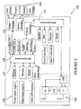
- FIG. 2 depicts an exemplary internal configuration 200 of handheld device 140.
- Microprocessor 210 is designed to run a variety of applications (shown generally at 230) while microprocessor 220 is designed to run radio transmission/ receive functions (shown generally at 240) and power management 250 functions.
- rechargeable battery 260 provides power to microprocessors 210, 220 along with other components integral to handheld device 140.
- advanced versions of handheld device 140 may use a single processor, several examples of which are known widely in the art.
- USB charging When rechargeable battery 260 is dead it can be recharged through USB port. 270 using, for example, USB charger and sync cable 100 discussed above.
- USB charging One issue associated with USB charging is that handheld device 140 can draw no more than 100 mA from the USB bus before handheld device 140 is enumerated with the host computer. More specifically, according to USB Specification Revision 2.0, when a USB device ("hub” or "function") is attached to or removed from the universal serial bus, the host controller uses a process known as bus enumeration to identify and manage the device state changes necessary. For example, when a USB peripheral is attached to a powered USB port, the host controller will issue a port enable and reset command to that port.
- the USB peripheral When the port has been enabled, the USB peripheral is now in Default state and can draw no more than 100mA until it is properly configured. Once the USB peripheral is configured it can draw up to 500mA if the connected port is a high power port.
- current limiting circuits are included in handheld device 200 to limit the current draw to less than 100 mA. With less than 100 mA current, if rechargeable battery 260 is very low, dead or not inserted there is a good possibility that there is not enough power available to start the chipset of handheld device 140. If the chipset can't be powered up, the enumeration process can't be accomplished.
- the power management integrated circuit (IC) is an essential element of modern low power handheld devices. To be able to maximize the power saving, most handheld processors have their own tightly coupled power management IC designed to work with it together.
- the power management IC has a group of power switches and regulators to provide power for each section of the handheld device.
- the processor has software/firmware to turn on and off each power switch and power regulator as required to faciliate normal operation and power saving.
- handheld device 140 configured with a single processor could be powered up under the 100mA limitation.
- One approach is to use a separate power supply for the single processor.
- the power management chip is fully integrated with the single processor, then this solution may not be acceptable due to the complicated power up/ power down sequence, power failure handling, power saving management, etc. performed by the power management IC.
- a solution to address this configuration is therefore required which is relatively inexpensive to implement and which occupies a minimum amount of space within handheld device 140.
- the proposed solution detailed in the present application provides, in a first embodiment, a handheld device with an added USB microcontroller.
- the USB microcontroller has an integrated USB transceiver, microcontroller, RAM, and Flash Memory or EPROM.
- the USB microcontroller is an off-the-shelf product, widely used on current USB devices such as USB storage drives, digital cameras, USB mice or the like. The cost of such USB microcontrollers is relatively low and their size is suitable for use in a handheld device.
- the integrated USB microcontroller is only powered up when the USB charging and synch cable is plugged in and the rechargeable battery is absent or below the voltage threshold to power up the handheld device with less than 100mA pre-enumeration USB current.
- the integrated USB microcontroller performs USB enumeration with the host computer via a USB charging and sync cable, so that the charging current can be increased to 500mA post enumeration (assuming the handheld device is connected to the high power port) or the host can keep charging the device battery with 100 mA current if the device has a very low or dead battery and the handheld device is connected to a low power port.
- the rechargeable battery is charged to above the threshold for the handheld device chipset or when 500 mA current can be drawn from it, the chipset of the handheld device is powered up to take over USB communication from the USB microcontroller.
- An alternate embodiment incorporates an integrated USB hub controller.
- USB charging cable When the USB charging cable is initially plugged in, only the USB hub controller is powered up, thereby requiring much less current to perform the enumeration with the host computer. Once the rechargeable battery level is high enough or it is allowed to draw 500 mA post enumeration, the main processor of the handheld device is started and functions as a device connected to the USB hub controller.
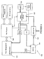
- Figure 3 depicts the first embodiment of an exemplary internal configuration 300 of handheld device 140 in accordance with the proposed solution.
- Handheld device 140 is a "function" under USB Specification Revision 2.0.
- functions are divided into bus-powered and self-powered classes. Bus-powered functions draw all their power from their USB connection, while self-powered functions draw power from an external power source. Bus-powered functions are further categorized as low-power and high-power. Low-power functions can be powered from either a self-powered or bus-powered "hub", but high-power functions are connected to self-powered hubs in order to have sufficient power to operate.
- handheld device 140 can be a bus-powered, low-power function, a bus-powered, high-power function, or a self-powered function depending on the working state of handheld device 140.
- battery 340 is absent or when handheld device 300 is in a charging state and the level of battery 340 is below the voltage threshold required to power up handheld device 140
- handheld device 140 is a bus-powered, high-power function.
- hand-held device 140 can be configured as a bus-powered, low-power function.
- battery 340 of handheld device 140 is fully charged, or when handheld device 140 has turned the charging circuit off, it is a self-powered function.
- a single processor 310 communicates with a power management integrated circuit (IC) 320 and serves to control not only RF circuits 330 but also a variety of application modules (not shown) and peripherals such as a liquid crystal display (LCD) and memory 325.
- Rechargeable battery 340 communicates with USB charger integrated circuit 350 which may connect through port 360 to a host controller/hub in a computer via a USB charging and sync cable (not shown).
- USB charger integrated circuit may, for example, be a bqTINYIII TM Single-Chip Charge and Dynamic Power-Path Management. (DPPM) IC offered by Texas Instruments, which allows an AC adapter or USB port connection to simultaneously power the system and recharge battery 340.
- DPPM Dynamic Power-Path Management.
- the bqTINYIII TM also allows for the system to instantaneously turn on from an external power source when rechargeable battery 340 is absent, deeply discharged or dead.
- this charger IC starts with an input limiting rate of 100mA due to the enumeration restriction imposed under USB Specification Revision 2.0, the contents of which are herein incorporated by reference.
- 100mA is insufficient to start processor 310 and power management IC 320.
- USB microcontroller 370 connected through USB multiplexer 380 performs USB enumeration with the host controller/hub integral to the laptop, at less than the 100mA current draw restriction.
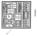
- the USB microcontrollers (C8051F320 and C8051F321) offered by Silicon Laboratories would be suitable, a block diagram of which is depicted in Figure 4 .
- the chip which embodies the USB microcontroller is a tiny 5mm x 5mm, 28-pin Micro Lead-Frame Package (MLP); sufficiently small to integrate easily into the circuitry of handheld device 140.
- MLP Micro Lead-Frame Package
- USB microcontroller 370 is only powered up when the USB charging cable is plugged into port 360 and the level of rechargeable battery 340 is below the threshold to power up handheld device 140 with less than 100mA pre-enumeration USB current. Essentially, since USB microcontroller 370 can be powered up using less than 100mA, it fulfills the enumeration function with the host laptop, thereby allowing the charging current to rise to 500mA post enumeration (in accordance with USB Specification Revision 2.0), sufficient to start the chipset of handheld device 140.
- USB microcontroller 370 maintains the USB connection until battery 340 is charged beyond the threshold, sufficient to start the chipset of handheld device 140. Once the chipset is powered up, handheld device 300 takes over USB communication from USB microcontroller 370.
- USB multiplexer 380 is controlled by USB microcontroller 370 and battery level comparator 395.
- USB microcontroller power supply default is in the ON state. As soon as single processor 310 is powered up, the power supply to USB microcontroller 360 is powered off. This serves to extend the life of rechargeable battery 340, as well as eliminating the complicated inter-processor communication.
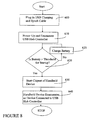
- Figure 5 depicts a flowchart highlighting the steps in the enumeration process of handheld device 140 having exemplary internal configuration 300.
- the USB charging and synch cable is plugged in.
- step 440 If it is determined at step 440 that the level of rechargeable battery 340 is above the power up threshold for handheld device 140 or when 500mA current can be drawn, then, at step 450, the chipset of handheld device 140 is started. Once the chipset is started, at step 460, USB communication is taken over by handheld device 140 from USB microcontroller 370.
- USB hub controller 510 replaces USB microcontroller 370.
- Handheld device 140 also includes a USB charger IC 520 and power management IC 530 serving similar functions to those previously discussed in relation to Figure 3 .
- USB charger IC 520 and power management IC 530 serving similar functions to those previously discussed in relation to Figure 3 .
- USB hub controller 510 requires less than the 100mA pre-enumeration current available to power up.
- USB hub controller 510 may also be an off-the-shelf controller designed for handheld devices.
- One such USB hub controller 510 is the USB20H04 4-Port USB2.0 Hub Controller offered by SMSC, a block diagram of which is depicted at Figure 7 .
- root hub integral to the host laptop can connect to either "hubs" or "functions”.
- hubs like functions, can be bus-powered or self-powered or a combination thereof.
- the USB20H04 supports bus-powered, self-powered and dynamic-powered configurations. For self-powered operation, an external supply (e.g. rechargeable battery 550) is used to power the downstream facing ports (shown generally at 570).
- an external supply e.g. rechargeable battery 550
- the downstream facing ports shown generally at 570.
- USB20H04 In bus-powered mode, all power is derived from the upstream facing port 580 (i.e. the USB connection to the host laptop) and no external power supply is required. With dynamic-powered mode, USB20H04 automatically switches to bus-powered mode if a local power source is available. In the preferred embodiment, the dynamic-powered mode allows USB hub controller 510 to be powered by the host laptop to which it is connected during charging of rechargeable battery 550, following which USB hub controller 510 is powered by rechargeable battery 550.
- FIG 8 is a flow chart highlighting the steps in the enumeration process of handheld device 140 having exemplary internal configuration 500.
- the USB charging and synch cable is plugged in.
- USB hub controller 510 is powered up and enumerated using the 100mA pre-enumeration current. If it is determined at step 620 that the level of rechargeable battery 520 is above the power up threshold for handheld device 140 or when 500mA current can be drawn, then, at step 630, the chipset of handheld device 140 is started. Once the chipset is started, at step 640, handheld device 140 is enumerated as a device connected to USB hub controller 510. If, at step 620, it is determined that the level of rechargeable battery 520 is not above the power up threshold for handheld device 140 or that 500mA current cannot be drawn, then at step 625 the battery continues to charge.
- the enumeration steps detailed in Figure 5 represent only those which are most applicable to the embodiment of the proposed solution. As will be appreciated by those in the art, the enumeration process includes a number of other steps which are hereinafter defined for the sake of clarity.
- Enumeration is the initial exchange of information that accomplishes this task. The process includes assigning an address to the device, reading data structures from the device, assigning and loading a device driver, and selecting a configuration from the options presented in the retrieved data. The device is then configured and ready to transfer data using any of the endpoints in its configuration.
- One of the duties of a hub is to detect the attachment and removal of devices. Each hub has an interrupt IN pipe for reporting these events to the host computer.
- the host polls its root hub (integral to the computer) to learn if any devices are attached, including additional hubs and devices attached to the first tier of devices. After boot-up, the host continues to poll periodically to learn of any newly attached or removed devices.
- the host sends a series of requests to the device's hub, causing the hub to establish a communications path between the host and the device. The host then attempts to enumerate the device by sending control transfers containing standard USB requests to Endpoint 0. All USB devices must support control transfers, the standard requests, and Endpoint 0.
- Windows TM adds the new device to the Device Manager display in the Control Panel.
- Windows TM automatically removes the device from the display.
- the device's program code contains the information the host will request, and a combination of hardware and firmware decodes and responds to requests for the information.
- Some application-specific chips (ASICs) manage the enumeration entirely in hardware and require no firmware support.
- Windows TM handles the enumeration process automatically. Windows TM looks for a special text file called an INF file that identifies the driver to use for the device and then begins the enumeration process.
- a device moves through four of the six device states defined by the specification: Powered, Default, Address, and Configured. (The other states are Attached and Suspend.) In each state, the device has defined capabilities and behavior. The steps below are a typical sequence of events that occurs during enumeration under Windows TM :
- the host now assigns drivers for the interfaces in composite devices. As with other devices, the host uses the information retrieved from the device to find a matching driver. The device is now ready for use.
- USB microcontroller the chipset of a handheld device can be started even where the handheld device can draw no more than 100mA before the handheld device is enumerated with the computer host.
Landscapes
- Engineering & Computer Science (AREA)
- Theoretical Computer Science (AREA)
- General Engineering & Computer Science (AREA)
- Physics & Mathematics (AREA)
- General Physics & Mathematics (AREA)
- Computer Hardware Design (AREA)
- Power Sources (AREA)
- Charge And Discharge Circuits For Batteries Or The Like (AREA)
- Information Transfer Systems (AREA)
- Lock And Its Accessories (AREA)
- Air Bags (AREA)
Claims (8)
- Tragbares Kommunikationsgerät (140), das Folgendes umfasst:einen USB-Anschluss (360), der für die Verbindung mit einem USB Host Controller angepasst ist, wobei der USB Host Controller den USB-Anschluss unter einem Stromschwellwert vor der Aufzählung des tragbaren Kommunikationsgeräts und über dem Stromschwellwert nach der Aufzählung des tragbaren Kommunikationsgeräts mit Strom versorgt;einen ersten Prozessor (370), wobei der erste Prozessor zum Starten, sobald der zugeführte Strom unter dem Stromschwellwert liegt, angepasst ist;einen zweiten Prozessor (310), wobei der zweite Prozessor Teil eines Chipsatzes ist, der erfordert, dass der zugeführte Strom über dem Stromschwellwert liegt, um zu starten;eine Stromüberwachungsschaltung (320), die von dem zweiten Prozessor (310) getrennt ist; und einen Multiplexer (380), wobei sich der Multiplexer auf einem Kommunikationspfad zwischen dem USB-Anschluss (360) und dem ersten Prozessor (370) und zweiten Prozessor (310) befindet, wobei der erste Prozessor ein USB-Mikrocontroller (370) ist und angepasst ist, um mit dem USB Host Controller aufzuzählen, um Strom über dem Schwellwert zu bekommen, und wobei der zweite Prozessor (310) angepasst ist, um die Kommunikation über den USB-Anschluss (360) durch das tragbare Gerät (140) von dem ersten Prozessor (370) her beim Starten des zweiten Prozessors (310) zu übernehmen, und das tragbare Gerät (140) angepasst ist, um den ersten Prozessor (370) beim Starten des zweiten Prozessors (310) abzuschalten.
- Tragbares Kommunikationsgerät (140) nach Anspruch 1, wobei der Stromschwellwert 100 mA beträgt.
- Tragbares Kommunikationsgerät (140) nach Anspruch 1 oder Anspruch 2, das des Weiteren eine wiederaufladbare Batterie (340) und eine integrierte Stromüberwachungsschaltung (320) umfasst, wobei der zweite Prozessor (310) mit Hilfe der wiederaufladbaren Batterie (340) gestartet wird, wenn ein Strom über dem Stromschwellwert aus der wiederaufladbaren Batterie (340) aufgenommen werden kann, wobei das tragbare Kommunikationsgerät (140) angepasst ist, um das Starten des ersten Prozessors (370) zu vermeiden, wenn der zweite Prozessor (310) mit Hilfe der wiederaufladbaren Batterie (340) gestartet wird.
- Tragbares Kommunikationsgerät (140) nach Anspruch 3, das des Weiteren eine Aufladevorrichtung (350) zwischen dem USB-Anschluss (360) und der wiederaufladbaren Batterie (340) umfasst.
- Verfahren des Aufzählens eines zweiten Prozessors (310) in einem tragbaren Kommunikationsgerät (140), wobei das tragbare Kommunikationsgerät (140) über einen ersten Prozessor (370) verfügt, der zum Starten mit einem Strom unter einem Stromschwellwert in der Lage ist, und ein zweiter Prozessor (310) Teil eines Chipsatzes ist, der erfordert, dass Strom über dem Stromschwellwert liegt, um zu starten, wobei das tragbare Kommunikationsgerät des Weiteren eine von dem zweiten Prozessor (310) getrennte Stromüberwachungsschaltung (320) umfasst, wobei das Verfahren folgende Schritte umfasst:Starten des ersten Prozessors (370);Über einen USB-Anschluss (360) Aufzählen des ersten Prozessors (370) mit einem USB Host Controller, der zum Versorgen mit Strom unter dem Stromschwellwert vor der Aufzählung und über dem Stromschwellwert nach der Aufzählung in der Lage ist;Starten des zweiten Prozessors (310);Übernehmen von Kommunikationen zwischen dem USB Host Controller und dem tragbaren Kommunikationsgerät (140) an dem zweiten Prozessor (310), wobei das tragbare Kommunikationsgerät einen Multiplexer (380) umfasst, wobei der Schritt des Übernehmens den Multiplexer (380) nutzt, um Kommunikationen an den zweiten Prozessor (310) zu leiten; undAbschalten des ersten Prozessors (370) beim Starten des zweiten Prozessors (310), wobei der erste Prozessor ein USB-Mikrocontroller (370) ist.
- Verfahren nach Anspruch 5, wobei das Abschalten unter Nutzung der integrierten Stromüberwachungsschaltung (320) durchgeführt wird.
- Verfahren nach einem der Ansprüche 5 bis 6, das des Weiteren den Schritt des Aufladens einer wiederaufladbaren Batterie (340) auf dem tragbaren Kommunikationsgerät (140) unter Nutzung der integrierten Stromüberwachungsschaltung (320) umfasst.
- Verfahren nach Anspruch 7, wobei, wenn die wiederaufladbare Batterie (340) zum Versorgen mit Strom zum Starten des zweiten Prozessors (310) in der Lage ist, das Verfahren die Schritte des Startens des ersten Prozessors (370) und des Aufzählens auslässt.
Priority Applications (5)
| Application Number | Priority Date | Filing Date | Title |
|---|---|---|---|
| EP05109552A EP1775652B1 (de) | 2005-10-13 | 2005-10-13 | Vorrichtung und Verfahren zur Unterstützung der USB-Aufzählung eines BUS-betriebenen tragbaren Geräts |
| ES05109552T ES2299963T3 (es) | 2005-10-13 | 2005-10-13 | Aparato y metodo para soportar la enumeracion usb de un dispositivo portatil alimentado por bus. |
| DE602005005065T DE602005005065T2 (de) | 2005-10-13 | 2005-10-13 | Vorrichtung und Verfahren zur Unterstützung der USB-Aufzählung eines BUS-betriebenen tragbaren Geräts |
| AT05109552T ATE387653T1 (de) | 2005-10-13 | 2005-10-13 | Vorrichtung und verfahren zur unterstützung der usb-aufzählung eines bus-betriebenen tragbaren geräts |
| CA2562776A CA2562776C (en) | 2005-10-13 | 2006-10-06 | Apparatus and method to support usb enumeration of a bus powered handheld device |
Applications Claiming Priority (1)
| Application Number | Priority Date | Filing Date | Title |
|---|---|---|---|
| EP05109552A EP1775652B1 (de) | 2005-10-13 | 2005-10-13 | Vorrichtung und Verfahren zur Unterstützung der USB-Aufzählung eines BUS-betriebenen tragbaren Geräts |
Publications (2)
| Publication Number | Publication Date |
|---|---|
| EP1775652A1 EP1775652A1 (de) | 2007-04-18 |
| EP1775652B1 true EP1775652B1 (de) | 2008-02-27 |
Family
ID=35645774
Family Applications (1)
| Application Number | Title | Priority Date | Filing Date |
|---|---|---|---|
| EP05109552A Expired - Lifetime EP1775652B1 (de) | 2005-10-13 | 2005-10-13 | Vorrichtung und Verfahren zur Unterstützung der USB-Aufzählung eines BUS-betriebenen tragbaren Geräts |
Country Status (5)
| Country | Link |
|---|---|
| EP (1) | EP1775652B1 (de) |
| AT (1) | ATE387653T1 (de) |
| CA (1) | CA2562776C (de) |
| DE (1) | DE602005005065T2 (de) |
| ES (1) | ES2299963T3 (de) |
Families Citing this family (12)
| Publication number | Priority date | Publication date | Assignee | Title |
|---|---|---|---|---|
| US7523338B2 (en) | 2005-10-13 | 2009-04-21 | Research In Motion Limited | Apparatus and method to support USB enumeration of a bus powered handheld device |
| PL2130108T3 (pl) | 2007-03-29 | 2018-07-31 | Nokia Technologies Oy | Podłączenie do urządzenia USB |
| US7631126B2 (en) | 2007-05-24 | 2009-12-08 | Research In Motion Limited | System and method for interfacing an electronic device with a host system |
| EP1995666B1 (de) * | 2007-05-24 | 2009-07-15 | Research In Motion Limited | System und Verfahren zum Ankoppeln einer elektronischen Vorrichtung an ein Hostsystem |
| US8260370B2 (en) | 2008-01-03 | 2012-09-04 | Kyocera Corporation | Method and apparatus for powering a wireless peripheral |
| US7873774B2 (en) * | 2008-02-01 | 2011-01-18 | Telefonaktiebolaget Lm Ericsson (Publ) | Connections and dynamic configuration of interfaces for mobile phones and multifunctional devices |
| EP2110034A1 (de) * | 2008-04-17 | 2009-10-21 | Philip Morris Products S.A. | Elektrisch erhitztes Rauchsystem |
| WO2010109984A1 (ja) * | 2009-03-24 | 2010-09-30 | コニカミノルタエムジー株式会社 | 放射線画像検出システム |
| DE102011009898A1 (de) * | 2011-01-31 | 2012-08-02 | Castellan Ag | Vorrichtung zur Aufbewahrung elektrischer, mit Akkus versehener Verbraucher |
| KR20150001502A (ko) * | 2013-06-27 | 2015-01-06 | 삼성전자주식회사 | 전자 장치 및 제어 방법 |
| US9804977B2 (en) * | 2015-04-28 | 2017-10-31 | Microchip Technology Incorporated | Universal serial bus smart hub |
| CN112437335B (zh) * | 2020-11-11 | 2023-01-24 | 海信视像科技股份有限公司 | 显示设备及其外接设备连接处理方法 |
Citations (2)
| Publication number | Priority date | Publication date | Assignee | Title |
|---|---|---|---|---|
| EP1085400A2 (de) * | 1999-09-14 | 2001-03-21 | Texas Instruments Incorporated | Verfahren und Vorrichtung zur Leistubgsversorgung für ein tragbares elektronische Gerät |
| US20040003309A1 (en) * | 2002-06-26 | 2004-01-01 | Cai Zhong-Ning | Techniques for utilization of asymmetric secondary processing resources |
Family Cites Families (2)
| Publication number | Priority date | Publication date | Assignee | Title |
|---|---|---|---|---|
| US6665801B1 (en) * | 2000-01-27 | 2003-12-16 | Symbol Technologies, Inc. | Method and apparatus for charging a self powered USB device at different charge rates according to the charge level of a rechargeable element on the device |
| JP3674855B2 (ja) * | 2002-03-20 | 2005-07-27 | ソニー株式会社 | 電源制御装置および電源制御方法 |
-
2005
- 2005-10-13 EP EP05109552A patent/EP1775652B1/de not_active Expired - Lifetime
- 2005-10-13 DE DE602005005065T patent/DE602005005065T2/de not_active Expired - Lifetime
- 2005-10-13 ES ES05109552T patent/ES2299963T3/es not_active Expired - Lifetime
- 2005-10-13 AT AT05109552T patent/ATE387653T1/de not_active IP Right Cessation
-
2006
- 2006-10-06 CA CA2562776A patent/CA2562776C/en active Active
Patent Citations (2)
| Publication number | Priority date | Publication date | Assignee | Title |
|---|---|---|---|---|
| EP1085400A2 (de) * | 1999-09-14 | 2001-03-21 | Texas Instruments Incorporated | Verfahren und Vorrichtung zur Leistubgsversorgung für ein tragbares elektronische Gerät |
| US20040003309A1 (en) * | 2002-06-26 | 2004-01-01 | Cai Zhong-Ning | Techniques for utilization of asymmetric secondary processing resources |
Also Published As
| Publication number | Publication date |
|---|---|
| DE602005005065T2 (de) | 2009-03-19 |
| ES2299963T3 (es) | 2008-06-01 |
| CA2562776C (en) | 2010-12-21 |
| CA2562776A1 (en) | 2007-04-13 |
| ATE387653T1 (de) | 2008-03-15 |
| EP1775652A1 (de) | 2007-04-18 |
| DE602005005065D1 (de) | 2008-04-10 |
Similar Documents
| Publication | Publication Date | Title |
|---|---|---|
| US7523338B2 (en) | Apparatus and method to support USB enumeration of a bus powered handheld device | |
| CN100487686C (zh) | 通用串行总线设备和用于执行内部通信的装置 | |
| CN101901201B (zh) | 一种在电子设备上实现usb otg功能的方法和装置 | |
| KR100755971B1 (ko) | 듀얼 인터페이스 방식으로 동작하는 단일 포트 유에스비장치 | |
| EP2130108B1 (de) | Verbindung mit einer usb-einrichtung | |
| CA2634656C (en) | Charging status indicator control system and method | |
| US7895386B2 (en) | USB interface provided with host/device function and its control method | |
| US20100109602A1 (en) | Charging device and method of operating the same | |
| CN108988431B (zh) | 一种多协议充电装置以及多协议充电方法 | |
| US20150046727A1 (en) | Feeding method and electronic apparatus | |
| CA2562776C (en) | Apparatus and method to support usb enumeration of a bus powered handheld device | |
| CN103477301B (zh) | 用于对储能装置进行充电的方法和装置 | |
| CN103631355B (zh) | 信息处理系统以及外部设备 | |
| EP2487775A1 (de) | Mobiles endgerät sowie stromversorgungssystem, stromversorgungsverfahren und stromversorgungsprogramm für das mobile endgerät | |
| CN108123515A (zh) | 可充电电子设备 | |
| WO2022095606A1 (zh) | 信息读取方法、设备、线缆、充电系统及计算机存储介质 | |
| US20070035276A1 (en) | Charging system for charging accumulator means in an electronic device, and a charging apparatus and an electronic device for the system | |
| CN102263423B (zh) | 通用串行总线充电系统及其充电方法 | |
| CN115793823A (zh) | 端口控制器、电子设备 | |
| WO2025213505A1 (zh) | 基于e2c协议的电池管理控制器及其系统、供电系统 | |
| CN119561179A (zh) | 功率共享方法、功率共享系统和多端口功率传输系统 | |
| CN1879276A (zh) | 用于给电子设备中的蓄电池装置充电的充电系统、以及用于该系统的充电设备和电子设备 | |
| CN219960177U (zh) | 充电装置 | |
| KR200329963Y1 (ko) | 컴퓨터와 휴대용기기 간의 충전 및 통신 케이블 장치 | |
| US11432384B2 (en) | LED control for reversable power cable |
Legal Events
| Date | Code | Title | Description |
|---|---|---|---|
| PUAI | Public reference made under article 153(3) epc to a published international application that has entered the european phase |
Free format text: ORIGINAL CODE: 0009012 |
|
| 17P | Request for examination filed |
Effective date: 20051013 |
|
| AK | Designated contracting states |
Kind code of ref document: A1 Designated state(s): AT BE BG CH CY CZ DE DK EE ES FI FR GB GR HU IE IS IT LI LT LU LV MC NL PL PT RO SE SI SK TR |
|
| AX | Request for extension of the european patent |
Extension state: AL BA HR MK YU |
|
| GRAP | Despatch of communication of intention to grant a patent |
Free format text: ORIGINAL CODE: EPIDOSNIGR1 |
|
| RIC1 | Information provided on ipc code assigned before grant |
Ipc: G06F 1/26 20060101AFI20070713BHEP Ipc: G06F 1/32 20060101ALN20070713BHEP |
|
| GRAS | Grant fee paid |
Free format text: ORIGINAL CODE: EPIDOSNIGR3 |
|
| AKX | Designation fees paid |
Designated state(s): AT BE BG CH CY CZ DE DK EE ES FI FR GB GR HU IE IS IT LI LT LU LV MC NL PL PT RO SE SI SK TR |
|
| AXX | Extension fees paid |
Extension state: MK Payment date: 20051013 Extension state: HR Payment date: 20051013 Extension state: BA Payment date: 20051013 Extension state: AL Payment date: 20051013 Extension state: YU Payment date: 20051013 |
|
| GRAA | (expected) grant |
Free format text: ORIGINAL CODE: 0009210 |
|
| AK | Designated contracting states |
Kind code of ref document: B1 Designated state(s): AT BE BG CH CY CZ DE DK EE ES FI FR GB GR HU IE IS IT LI LT LU LV MC NL PL PT RO SE SI SK TR |
|
| AX | Request for extension of the european patent |
Extension state: AL BA HR MK YU |
|
| REG | Reference to a national code |
Ref country code: GB Ref legal event code: FG4D |
|
| REG | Reference to a national code |
Ref country code: CH Ref legal event code: EP |
|
| REG | Reference to a national code |
Ref country code: IE Ref legal event code: FG4D |
|
| REF | Corresponds to: |
Ref document number: 602005005065 Country of ref document: DE Date of ref document: 20080410 Kind code of ref document: P |
|
| REG | Reference to a national code |
Ref country code: ES Ref legal event code: FG2A Ref document number: 2299963 Country of ref document: ES Kind code of ref document: T3 |
|
| PG25 | Lapsed in a contracting state [announced via postgrant information from national office to epo] |
Ref country code: IS Free format text: LAPSE BECAUSE OF FAILURE TO SUBMIT A TRANSLATION OF THE DESCRIPTION OR TO PAY THE FEE WITHIN THE PRESCRIBED TIME-LIMIT Effective date: 20080627 Ref country code: FI Free format text: LAPSE BECAUSE OF FAILURE TO SUBMIT A TRANSLATION OF THE DESCRIPTION OR TO PAY THE FEE WITHIN THE PRESCRIBED TIME-LIMIT Effective date: 20080227 |
|
| NLV1 | Nl: lapsed or annulled due to failure to fulfill the requirements of art. 29p and 29m of the patents act | ||
| PG25 | Lapsed in a contracting state [announced via postgrant information from national office to epo] |
Ref country code: AT Free format text: LAPSE BECAUSE OF FAILURE TO SUBMIT A TRANSLATION OF THE DESCRIPTION OR TO PAY THE FEE WITHIN THE PRESCRIBED TIME-LIMIT Effective date: 20080227 |
|
| ET | Fr: translation filed | ||
| PG25 | Lapsed in a contracting state [announced via postgrant information from national office to epo] |
Ref country code: PL Free format text: LAPSE BECAUSE OF FAILURE TO SUBMIT A TRANSLATION OF THE DESCRIPTION OR TO PAY THE FEE WITHIN THE PRESCRIBED TIME-LIMIT Effective date: 20080227 Ref country code: BE Free format text: LAPSE BECAUSE OF FAILURE TO SUBMIT A TRANSLATION OF THE DESCRIPTION OR TO PAY THE FEE WITHIN THE PRESCRIBED TIME-LIMIT Effective date: 20080227 Ref country code: SI Free format text: LAPSE BECAUSE OF FAILURE TO SUBMIT A TRANSLATION OF THE DESCRIPTION OR TO PAY THE FEE WITHIN THE PRESCRIBED TIME-LIMIT Effective date: 20080227 Ref country code: LV Free format text: LAPSE BECAUSE OF FAILURE TO SUBMIT A TRANSLATION OF THE DESCRIPTION OR TO PAY THE FEE WITHIN THE PRESCRIBED TIME-LIMIT Effective date: 20080227 |
|
| PG25 | Lapsed in a contracting state [announced via postgrant information from national office to epo] |
Ref country code: SE Free format text: LAPSE BECAUSE OF FAILURE TO SUBMIT A TRANSLATION OF THE DESCRIPTION OR TO PAY THE FEE WITHIN THE PRESCRIBED TIME-LIMIT Effective date: 20080527 Ref country code: CZ Free format text: LAPSE BECAUSE OF FAILURE TO SUBMIT A TRANSLATION OF THE DESCRIPTION OR TO PAY THE FEE WITHIN THE PRESCRIBED TIME-LIMIT Effective date: 20080227 Ref country code: NL Free format text: LAPSE BECAUSE OF FAILURE TO SUBMIT A TRANSLATION OF THE DESCRIPTION OR TO PAY THE FEE WITHIN THE PRESCRIBED TIME-LIMIT Effective date: 20080227 Ref country code: DK Free format text: LAPSE BECAUSE OF FAILURE TO SUBMIT A TRANSLATION OF THE DESCRIPTION OR TO PAY THE FEE WITHIN THE PRESCRIBED TIME-LIMIT Effective date: 20080227 Ref country code: PT Free format text: LAPSE BECAUSE OF FAILURE TO SUBMIT A TRANSLATION OF THE DESCRIPTION OR TO PAY THE FEE WITHIN THE PRESCRIBED TIME-LIMIT Effective date: 20080721 Ref country code: SK Free format text: LAPSE BECAUSE OF FAILURE TO SUBMIT A TRANSLATION OF THE DESCRIPTION OR TO PAY THE FEE WITHIN THE PRESCRIBED TIME-LIMIT Effective date: 20080227 |
|
| PG25 | Lapsed in a contracting state [announced via postgrant information from national office to epo] |
Ref country code: RO Free format text: LAPSE BECAUSE OF FAILURE TO SUBMIT A TRANSLATION OF THE DESCRIPTION OR TO PAY THE FEE WITHIN THE PRESCRIBED TIME-LIMIT Effective date: 20080227 |
|
| PLBE | No opposition filed within time limit |
Free format text: ORIGINAL CODE: 0009261 |
|
| STAA | Information on the status of an ep patent application or granted ep patent |
Free format text: STATUS: NO OPPOSITION FILED WITHIN TIME LIMIT |
|
| PG25 | Lapsed in a contracting state [announced via postgrant information from national office to epo] |
Ref country code: LT Free format text: LAPSE BECAUSE OF FAILURE TO SUBMIT A TRANSLATION OF THE DESCRIPTION OR TO PAY THE FEE WITHIN THE PRESCRIBED TIME-LIMIT Effective date: 20080227 |
|
| 26N | No opposition filed |
Effective date: 20081128 |
|
| PG25 | Lapsed in a contracting state [announced via postgrant information from national office to epo] |
Ref country code: EE Free format text: LAPSE BECAUSE OF FAILURE TO SUBMIT A TRANSLATION OF THE DESCRIPTION OR TO PAY THE FEE WITHIN THE PRESCRIBED TIME-LIMIT Effective date: 20080227 Ref country code: BG Free format text: LAPSE BECAUSE OF FAILURE TO SUBMIT A TRANSLATION OF THE DESCRIPTION OR TO PAY THE FEE WITHIN THE PRESCRIBED TIME-LIMIT Effective date: 20080527 |
|
| PG25 | Lapsed in a contracting state [announced via postgrant information from national office to epo] |
Ref country code: MC Free format text: LAPSE BECAUSE OF NON-PAYMENT OF DUE FEES Effective date: 20081031 |
|
| PG25 | Lapsed in a contracting state [announced via postgrant information from national office to epo] |
Ref country code: CY Free format text: LAPSE BECAUSE OF FAILURE TO SUBMIT A TRANSLATION OF THE DESCRIPTION OR TO PAY THE FEE WITHIN THE PRESCRIBED TIME-LIMIT Effective date: 20080227 |
|
| PG25 | Lapsed in a contracting state [announced via postgrant information from national office to epo] |
Ref country code: IE Free format text: LAPSE BECAUSE OF NON-PAYMENT OF DUE FEES Effective date: 20081013 |
|
| REG | Reference to a national code |
Ref country code: CH Ref legal event code: PL |
|
| PG25 | Lapsed in a contracting state [announced via postgrant information from national office to epo] |
Ref country code: HU Free format text: LAPSE BECAUSE OF FAILURE TO SUBMIT A TRANSLATION OF THE DESCRIPTION OR TO PAY THE FEE WITHIN THE PRESCRIBED TIME-LIMIT Effective date: 20080828 Ref country code: LU Free format text: LAPSE BECAUSE OF NON-PAYMENT OF DUE FEES Effective date: 20081013 |
|
| PG25 | Lapsed in a contracting state [announced via postgrant information from national office to epo] |
Ref country code: TR Free format text: LAPSE BECAUSE OF FAILURE TO SUBMIT A TRANSLATION OF THE DESCRIPTION OR TO PAY THE FEE WITHIN THE PRESCRIBED TIME-LIMIT Effective date: 20080227 |
|
| PG25 | Lapsed in a contracting state [announced via postgrant information from national office to epo] |
Ref country code: GR Free format text: LAPSE BECAUSE OF FAILURE TO SUBMIT A TRANSLATION OF THE DESCRIPTION OR TO PAY THE FEE WITHIN THE PRESCRIBED TIME-LIMIT Effective date: 20080528 Ref country code: LI Free format text: LAPSE BECAUSE OF NON-PAYMENT OF DUE FEES Effective date: 20091031 Ref country code: CH Free format text: LAPSE BECAUSE OF NON-PAYMENT OF DUE FEES Effective date: 20091031 |
|
| REG | Reference to a national code |
Ref country code: DE Ref legal event code: R082 Ref document number: 602005005065 Country of ref document: DE Representative=s name: MERH-IP MATIAS ERNY REICHL HOFFMANN, DE |
|
| REG | Reference to a national code |
Ref country code: ES Ref legal event code: PC2A Owner name: BLACKBERRY LIMITED Effective date: 20141016 |
|
| REG | Reference to a national code |
Ref country code: DE Ref legal event code: R082 Ref document number: 602005005065 Country of ref document: DE Representative=s name: MERH-IP MATIAS ERNY REICHL HOFFMANN, DE Effective date: 20140925 Ref country code: DE Ref legal event code: R081 Ref document number: 602005005065 Country of ref document: DE Owner name: BLACKBERRY LIMITED, WATERLOO, CA Free format text: FORMER OWNER: RESEARCH IN MOTION LTD., WATERLOO, ONTARIO, CA Effective date: 20140925 Ref country code: DE Ref legal event code: R082 Ref document number: 602005005065 Country of ref document: DE Representative=s name: MERH-IP MATIAS ERNY REICHL HOFFMANN PATENTANWA, DE Effective date: 20140925 Ref country code: DE Ref legal event code: R081 Ref document number: 602005005065 Country of ref document: DE Owner name: FUNDAMENTAL INNOVATION SYSTEMS INTERNATIONAL L, US Free format text: FORMER OWNER: RESEARCH IN MOTION LTD., WATERLOO, ONTARIO, CA Effective date: 20140925 Ref country code: DE Ref legal event code: R082 Ref document number: 602005005065 Country of ref document: DE Representative=s name: VOSSIUS & PARTNER PATENTANWAELTE RECHTSANWAELT, DE Effective date: 20140925 |
|
| REG | Reference to a national code |
Ref country code: FR Ref legal event code: PLFP Year of fee payment: 11 |
|
| REG | Reference to a national code |
Ref country code: FR Ref legal event code: CA Effective date: 20151117 Ref country code: FR Ref legal event code: CD Owner name: BLACKBERRY LIMITED, CA Effective date: 20151117 |
|
| REG | Reference to a national code |
Ref country code: FR Ref legal event code: PLFP Year of fee payment: 12 |
|
| REG | Reference to a national code |
Ref country code: DE Ref legal event code: R082 Ref document number: 602005005065 Country of ref document: DE Representative=s name: MERH-IP MATIAS ERNY REICHL HOFFMANN PATENTANWA, DE Ref country code: DE Ref legal event code: R081 Ref document number: 602005005065 Country of ref document: DE Owner name: FUNDAMENTAL INNOVATION SYSTEMS INTERNATIONAL L, US Free format text: FORMER OWNER: BLACKBERRY LIMITED, WATERLOO, ONTARIO, CA Ref country code: DE Ref legal event code: R082 Ref document number: 602005005065 Country of ref document: DE Representative=s name: VOSSIUS & PARTNER PATENTANWAELTE RECHTSANWAELT, DE |
|
| REG | Reference to a national code |
Ref country code: DE Ref legal event code: R082 Ref document number: 602005005065 Country of ref document: DE Representative=s name: MERH-IP MATIAS ERNY REICHL HOFFMANN PATENTANWA, DE Ref country code: DE Ref legal event code: R081 Ref document number: 602005005065 Country of ref document: DE Owner name: FUNDAMENTAL INNOVATION SYSTEMS INTERNATIONAL L, US Free format text: FORMER OWNER: FUNDAMENTAL INNOVATION SYSTEMS INTERNATIONAL LLC, SOUTHLAKE, TEX., US Ref country code: DE Ref legal event code: R082 Ref document number: 602005005065 Country of ref document: DE Representative=s name: VOSSIUS & PARTNER PATENTANWAELTE RECHTSANWAELT, DE |
|
| REG | Reference to a national code |
Ref country code: FR Ref legal event code: PLFP Year of fee payment: 13 |
|
| REG | Reference to a national code |
Ref country code: FR Ref legal event code: TP Owner name: FUNDAMENTAL INNOVATION SYSTEMS INTERNATIONAL L, US Effective date: 20171127 |
|
| REG | Reference to a national code |
Ref country code: DE Ref legal event code: R082 Ref document number: 602005005065 Country of ref document: DE Representative=s name: VOSSIUS & PARTNER PATENTANWAELTE RECHTSANWAELT, DE |
|
| REG | Reference to a national code |
Ref country code: FR Ref legal event code: PLFP Year of fee payment: 14 |
|
| PGFP | Annual fee paid to national office [announced via postgrant information from national office to epo] |
Ref country code: ES Payment date: 20201103 Year of fee payment: 16 Ref country code: FR Payment date: 20201026 Year of fee payment: 16 Ref country code: IT Payment date: 20201023 Year of fee payment: 16 |
|
| PG25 | Lapsed in a contracting state [announced via postgrant information from national office to epo] |
Ref country code: FR Free format text: LAPSE BECAUSE OF NON-PAYMENT OF DUE FEES Effective date: 20211031 |
|
| PG25 | Lapsed in a contracting state [announced via postgrant information from national office to epo] |
Ref country code: IT Free format text: LAPSE BECAUSE OF NON-PAYMENT OF DUE FEES Effective date: 20211013 |
|
| PGFP | Annual fee paid to national office [announced via postgrant information from national office to epo] |
Ref country code: GB Payment date: 20221027 Year of fee payment: 18 Ref country code: DE Payment date: 20221027 Year of fee payment: 18 |
|
| REG | Reference to a national code |
Ref country code: ES Ref legal event code: FD2A Effective date: 20230202 |
|
| PG25 | Lapsed in a contracting state [announced via postgrant information from national office to epo] |
Ref country code: ES Free format text: LAPSE BECAUSE OF NON-PAYMENT OF DUE FEES Effective date: 20211014 |
|
| REG | Reference to a national code |
Ref country code: DE Ref legal event code: R119 Ref document number: 602005005065 Country of ref document: DE |
|
| GBPC | Gb: european patent ceased through non-payment of renewal fee |
Effective date: 20231013 |
|
| PG25 | Lapsed in a contracting state [announced via postgrant information from national office to epo] |
Ref country code: GB Free format text: LAPSE BECAUSE OF NON-PAYMENT OF DUE FEES Effective date: 20231013 |
|
| PG25 | Lapsed in a contracting state [announced via postgrant information from national office to epo] |
Ref country code: GB Free format text: LAPSE BECAUSE OF NON-PAYMENT OF DUE FEES Effective date: 20231013 Ref country code: DE Free format text: LAPSE BECAUSE OF NON-PAYMENT OF DUE FEES Effective date: 20240501 |