EP1775820A2 - Chargeur et dispositif électronique - Google Patents
Chargeur et dispositif électronique Download PDFInfo
- Publication number
- EP1775820A2 EP1775820A2 EP05256576A EP05256576A EP1775820A2 EP 1775820 A2 EP1775820 A2 EP 1775820A2 EP 05256576 A EP05256576 A EP 05256576A EP 05256576 A EP05256576 A EP 05256576A EP 1775820 A2 EP1775820 A2 EP 1775820A2
- Authority
- EP
- European Patent Office
- Prior art keywords
- charging
- power source
- constant
- current
- voltage
- Prior art date
- Legal status (The legal status is an assumption and is not a legal conclusion. Google has not performed a legal analysis and makes no representation as to the accuracy of the status listed.)
- Withdrawn
Links
Images









Classifications
-
- H—ELECTRICITY
- H02—GENERATION; CONVERSION OR DISTRIBUTION OF ELECTRIC POWER
- H02J—ELECTRIC POWER NETWORKS; CIRCUIT ARRANGEMENTS OR SYSTEMS FOR SUPPLYING OR DISTRIBUTING ELECTRIC POWER; SYSTEMS FOR STORING ELECTRIC ENERGY
- H02J7/00—Circuit arrangements for charging or discharging batteries or for supplying loads from batteries
- H02J7/02—Circuit arrangements for charging or discharging batteries or for supplying loads from batteries for charging batteries from AC mains by converters
-
- H—ELECTRICITY
- H02—GENERATION; CONVERSION OR DISTRIBUTION OF ELECTRIC POWER
- H02J—ELECTRIC POWER NETWORKS; CIRCUIT ARRANGEMENTS OR SYSTEMS FOR SUPPLYING OR DISTRIBUTING ELECTRIC POWER; SYSTEMS FOR STORING ELECTRIC ENERGY
- H02J4/00—Circuit arrangements for mains or distribution networks not specified as AC or DC; Circuit arrangements for mains or distribution networks combining AC and DC sections or sub-networks
- H02J4/20—Networks integrating separated AC and DC power sections
- H02J4/25—Networks integrating separated AC and DC power sections for transfer of electric power between AC and DC networks, e.g. for supplying the DC section within a load from an AC mains system
-
- H—ELECTRICITY
- H02—GENERATION; CONVERSION OR DISTRIBUTION OF ELECTRIC POWER
- H02J—ELECTRIC POWER NETWORKS; CIRCUIT ARRANGEMENTS OR SYSTEMS FOR SUPPLYING OR DISTRIBUTING ELECTRIC POWER; SYSTEMS FOR STORING ELECTRIC ENERGY
- H02J7/00—Circuit arrangements for charging or discharging batteries or for supplying loads from batteries
-
- H—ELECTRICITY
- H02—GENERATION; CONVERSION OR DISTRIBUTION OF ELECTRIC POWER
- H02J—ELECTRIC POWER NETWORKS; CIRCUIT ARRANGEMENTS OR SYSTEMS FOR SUPPLYING OR DISTRIBUTING ELECTRIC POWER; SYSTEMS FOR STORING ELECTRIC ENERGY
- H02J7/00—Circuit arrangements for charging or discharging batteries or for supplying loads from batteries
- H02J7/60—Circuit arrangements for charging or discharging batteries or for supplying loads from batteries including safety or protection arrangements
- H02J7/65—Circuit arrangements for charging or discharging batteries or for supplying loads from batteries including safety or protection arrangements against overtemperature
-
- H—ELECTRICITY
- H02—GENERATION; CONVERSION OR DISTRIBUTION OF ELECTRIC POWER
- H02J—ELECTRIC POWER NETWORKS; CIRCUIT ARRANGEMENTS OR SYSTEMS FOR SUPPLYING OR DISTRIBUTING ELECTRIC POWER; SYSTEMS FOR STORING ELECTRIC ENERGY
- H02J7/00—Circuit arrangements for charging or discharging batteries or for supplying loads from batteries
- H02J7/60—Circuit arrangements for charging or discharging batteries or for supplying loads from batteries including safety or protection arrangements
- H02J7/663—Circuit arrangements for charging or discharging batteries or for supplying loads from batteries including safety or protection arrangements using battery or load disconnect circuits
- H02J7/667—Circuit arrangements for charging or discharging batteries or for supplying loads from batteries including safety or protection arrangements using battery or load disconnect circuits disconnection of loads if battery is not under charge, e.g. in vehicle if engine is not running
-
- H—ELECTRICITY
- H02—GENERATION; CONVERSION OR DISTRIBUTION OF ELECTRIC POWER
- H02J—ELECTRIC POWER NETWORKS; CIRCUIT ARRANGEMENTS OR SYSTEMS FOR SUPPLYING OR DISTRIBUTING ELECTRIC POWER; SYSTEMS FOR STORING ELECTRIC ENERGY
- H02J7/00—Circuit arrangements for charging or discharging batteries or for supplying loads from batteries
- H02J7/90—Regulation of charging or discharging current or voltage
- H02J7/96—Regulation of charging or discharging current or voltage in response to battery voltage
Definitions
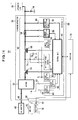
- Fig. 1 is a circuit diagram of a charging apparatus using a PMOS (P-channel Metal Oxide Semiconductor) transistor for charging control
- Fig. 2 is a flowchart of the charging control
- Fig. 3 is a diagram showing a charging operation.
- PMOS P-channel Metal Oxide Semiconductor
- This charging apparatus 2 is configured to use an AC adaptor 8 as a charging source to charge a rechargeable battery 6 built into an electronic device 3 along with an apparatus load 4.
- the charging apparatus 2 is provided with a charging IC 10, and the charging IC 10 integrates circuit units such as a charging control unit which can be integrated into an IC.
- a charging path 11 is formed for passing a charging current between the AC adaptor 8 and the rechargeable battery 6; the charging path 11 is equipped with a PMOS transistor (Tr) 12 as a charging control element; and the PMOSTr 12 is connected serially with a backflow prevention diode 14 and a sense resistor 16.
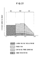
- the heat generation of the diode 14 is largest and accounts for one-half of the total heat generation amount.
- the total heat generation amount is larger than the constant-current charging CC1 region (t1 to t2), and the heat generation amounts of the diode 14 and sense resistor 16 is smaller than the CC1 region (t1 to t2), while the heat generation amounts of the PMOSTr 12 accounts for two third of the total heat generation amount.
- a start voltage of the constant-current charging CC1 is set to, for example, about 3 [V]
- the charging current Ic is dependent on the output of the AC adaptor 8 because the drooping characteristic of the AC adaptor 8 is used. Therefore, in the CC1 region, the charging current Ic is on the order of 670 [mA].
- Voa Vb + external part resistance [ ⁇ ] ⁇ Ic The external part generates heat depending on this acceptable loss.
- constant-voltage control is performed such that the battery voltage Vb will be 4.2 [V], and as the rechargeable battery 6 approaches full charge, the charging current Ic is reduced.
- the heat generation is lower than the CC2.
- the charging is completed and the charging operation is terminated if the charging current Ic reduced to on the order of 50 [mA].
- the power source unit may be fed with power from an external device connected to the electronic device and comprise of a first power source circuit outputting a constant current and a second power source circuit outputting a constant current smaller than the first power source circuit; and the control unit may be configured to apply the constant current from the second power source circuit to the rechargeable battery and switch output from the second power source circuit to the first power source circuit based on power-feeding information provided from the external device to apply the constant current to the rechargeable battery.
- heat radiation measures can be made lighter.
- heat radiation measures of a mobile terminal can be made lighter, which facilitates to make the product thinner.
- Fig. 2 is a flowchart showing a charging operation
- Fig. 5 is a diagram showing another charging apparatus
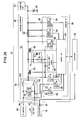
- Fig. 14 is a circuit diagram showing a charging operation in the case of using an AC adaptor
- Fig. 21 is a diagram showing a charging operation in the case of using a USB host
- a charging path 52 is formed between the switch 50 and the rechargeable battery 34.
- the charging path 11 is equipped with a PMOSTr 54 as a charging control circuit element, a PMOSTr 56 as a backflow prevention circuit element and a sense resistor 58 as a current detection element, which constitute a series circuit.
- the PMOSTr 54 is controlled by the charging IC 38 and applies a first constant current Icc1 to the rechargeable battery 34 through the charging path 52.
- the PMOSTr 56 is controlled by the charging IC 38 and prevents currents from flowing back from the rechargeable battery 34 through the charging path 52 to the AC adaptor 40 or USB host 42.
- the sense resistor 58 converts the charging current flowing through the charging path 52 to a voltage to be detected and the detected voltage is applied to the charging IC 38 as control information.
- the charging IC 38 is provided with an adaptor detection terminal 60 and a USB detection terminal 62 as well as a control unit 64, a switching power source 66 and a linear voltage regulator 68 as a built-in power source unit and others.
- the switching power source 66 is, for example, a DC-DC converter generating a constant-current output or constant-voltage output and constitutes a first power source circuit built into the charging IC 38.
- the linear voltage regulator 68 is, for example, an LDO (Low Drop Out) generating a constant current smaller than the constant current output from the switching power source 66, which is used for preliminary charging, and constitutes a second power source circuit built into the charging IC 38.
- the control unit 64 is constituted by a micro processor, for example.
- the preliminary charging is performed with the output current of the linear voltage regulator 68 by the power feeding of the USB host 42 as needed; after the preliminary charging, the constant-current charging CC2 is performed with the constant current Icc2 which is the output of the switching power source 66; after the charging, the constant-voltage charging CV is performed with the constant voltage Vc which is the output of the switching power source 66; and the rechargeable battery 34 is charged to a predetermined voltage. Also, in this charging, the charging current is detected by the sense resistor 58 and the detected current is applied to the control unit 64 as control information to perform the constant current control and the constant voltage control of the switching power source 66.
- the charging IC 38 is provided with the detection terminals 60, 62 for the AC adaptor 40 and the USB host 42 to determine connected devices from voltages applied to the detection terminals 60, 62, and if the USB host 42 is detected, the second constant-current charging CC2 and the constant-voltage charging CV are performed.
- the charging can be performed by feeding power from the USB host 42 to the switching power source 66 and by switching from the preliminary current Ipre to the constant current Icc2 (> Ipre) (e.g., Fig. 17). In this way, speed-up of the charging with low heat generation can be planned.
- the control method is in the case of connecting both the AC adaptor 40 and the USB host 42 as the charging sources.
- a battery status check is performed for the rechargeable battery 34 (step S11).
- the battery status check refers to the detected voltage of the voltage detection unit 84 and the like to check statuses such as the presence of the rechargeable battery 34, a battery temperature, a battery voltage and the like.
- the battery status check provides information about the necessity of the preliminary charging described above and the like.
- the constant current Icc2 is detected by the current detection unit 86 through the sense resistor 58 to be captured by the control unit 64 and is used by the control unit 64 for the constant-current control of the switching power source 66, and the constant current Icc2 flows through the charging path 52 via the switching power source 66.
- the constant current Icc2 raises the battery voltage to a voltage for starting the constant-voltage charging CV (step S17).
- the processor 76 determines whether the power-feeding capability of the USB host 42 is high or low, with the power-feeding information from the processor 78 (step S20). If the power-feeding capability is high, after the rechargeable battery 34 reaches to the predetermined voltage with the preliminary charging, the second constant-current charging CC2 is performed (step S21). In this case, the operation is switched from the linear voltage regulator 68 to the switching power source 66 to generate the constant current Icc2 from the switching power source 66, and the constant current Icc2 passes through the smoothing circuit 74 and is supplied from the charging path 52 to the rechargeable battery 34. A current value Icc2 or current value Icc3 ( ⁇ Icc2) is used for the constant current.
- Fig. 19 is a diagram showing the preliminary charging PR, the constant-current charging CC1, CC2 and the constant-voltage charging CV by defining the horizontal axis as the charging currents and the vertical axis as the battery voltages and the voltages on the charging source side.
- the maximum heat generation Hmax is dependent on the DC-DC conversion efficiency, as described above.
- Fig. 24 is a diagram showing the heat generation amount of the preliminary charging PR by defining the horizontal axis as the operation regions and the vertical axis as the heat generation amounts. In Fig. 24, the same symbols are added to the same portions as Fig. 22.
- the control unit 64 of the charging apparatus 36 detects a charging source connected to the charging apparatus 36 (step S31).
- the output voltage of the AC adaptor 40 is detected by the voltage detection unit 80 and the output voltage of the USB host 42 is detected by the voltage detection unit 82, an input voltage passing through the switch 50 is detected by the voltage detection unit 83.
- the voltage information is applied to the control unit 64 to determine the charging source.
- the relationship between the connected charging source and the input voltage is identified by such voltage detection and determination of the charging source.
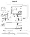
- the switch 50 is constituted by a first switch unit 50A and second switch unit 50B which can be switched by manual operation in an interlocked manner.
- the switch 50 is configured such that conduction through the switch unit 50B is lost when the switch unit 50A is made conductive and that conduction through the switch unit 50A is lost when the switch unit 50B is made conductive.
- the switch 108 may be constituted by either a circuit element switched by the control output of the control unit 64 built into the charging IC 38 or a mechanical switch manually operated by a user.
- the power-feeding plug 146 of the AC adaptor 40 is connected to the charging platform 104 to feeding power to the charging platform 104.
- a mount portion 148 is formed for detachably mounting the cellular phone 130, and a power-feeding unit provided in the mount portion 148 electrically contacts with the power-feeding terminal 106 (Fig. 30).
- the AC adaptor 40 is connected to the power-feeding terminal 106 of the cellular phone 130 via the charging platform 104.
Landscapes
- Engineering & Computer Science (AREA)
- Power Engineering (AREA)
- Charge And Discharge Circuits For Batteries Or The Like (AREA)
Applications Claiming Priority (1)
| Application Number | Priority Date | Filing Date | Title |
|---|---|---|---|
| JP2005193872A JP2007014163A (ja) | 2005-07-01 | 2005-07-01 | 充電用ic、充電装置及び電子機器 |
Publications (2)
| Publication Number | Publication Date |
|---|---|
| EP1775820A2 true EP1775820A2 (fr) | 2007-04-18 |
| EP1775820A3 EP1775820A3 (fr) | 2012-11-21 |
Family
ID=37588641
Family Applications (1)
| Application Number | Title | Priority Date | Filing Date |
|---|---|---|---|
| EP05256576A Withdrawn EP1775820A3 (fr) | 2005-07-01 | 2005-10-24 | Chargeur et dispositif électronique |
Country Status (3)
| Country | Link |
|---|---|
| US (1) | US7733060B2 (fr) |
| EP (1) | EP1775820A3 (fr) |
| JP (1) | JP2007014163A (fr) |
Cited By (1)
| Publication number | Priority date | Publication date | Assignee | Title |
|---|---|---|---|---|
| CN105247755A (zh) * | 2013-12-26 | 2016-01-13 | 联发科技股份有限公司 | 多路径充电器及其充电方法 |
Families Citing this family (52)
| Publication number | Priority date | Publication date | Assignee | Title |
|---|---|---|---|---|
| KR100731595B1 (ko) * | 2005-11-16 | 2007-06-22 | (주)에스피에스 | 휴대용 배터리 충전 및 비상 전원공급장치 |
| KR100782271B1 (ko) * | 2005-11-28 | 2007-12-04 | 엘지전자 주식회사 | 휴대 단말기의 충전 제어 장치 및 방법 |
| JP4657943B2 (ja) * | 2006-02-17 | 2011-03-23 | 株式会社リコー | 充電制御用半導体集積回路及びその充電制御用半導体集積回路を使用した2次電池の充電装置 |
| JP4877181B2 (ja) * | 2006-10-23 | 2012-02-15 | ソニー株式会社 | 充電装置および充電方法 |
| JP2008236878A (ja) * | 2007-03-19 | 2008-10-02 | Hitachi Koki Co Ltd | 充電装置 |
| US8004247B1 (en) * | 2007-04-26 | 2011-08-23 | Marvell International Ltd. | Switchable battery charger circuit |
| US20090027922A1 (en) * | 2007-07-24 | 2009-01-29 | Tracy Mark S | Power adapter |
| JP5057902B2 (ja) | 2007-09-06 | 2012-10-24 | 株式会社リコー | 充電制御回路 |
| JP5193619B2 (ja) * | 2008-01-31 | 2013-05-08 | 株式会社東芝 | 二次電池システム |
| CN101276319B (zh) * | 2008-02-05 | 2010-04-21 | 北京飞天诚信科技有限公司 | 一种将usb接口分时应用为标准i/o接口的设备及方法 |
| US20090237029A1 (en) * | 2008-03-24 | 2009-09-24 | Spx Corporation | Inductive battery charger for service equipment |
| JP5118534B2 (ja) * | 2008-03-31 | 2013-01-16 | 株式会社リコー | 充電装置 |
| CN101902064A (zh) * | 2009-05-27 | 2010-12-01 | 深圳富泰宏精密工业有限公司 | 充电装置及具有该充电装置的便携式电子装置 |
| JP5549184B2 (ja) * | 2009-10-29 | 2014-07-16 | 日立工機株式会社 | 充電装置 |
| JP5525862B2 (ja) * | 2010-02-26 | 2014-06-18 | 三洋電機株式会社 | 充電装置、プログラム |
| JP2012120267A (ja) | 2010-11-29 | 2012-06-21 | Toshiba Corp | 充電制御装置 |
| CN102570520A (zh) * | 2010-12-22 | 2012-07-11 | 深圳富泰宏精密工业有限公司 | 充电电路及其充电方法 |
| CN102801320A (zh) | 2011-05-24 | 2012-11-28 | 华硕电脑股份有限公司 | 电源供应器 |
| WO2012177193A1 (fr) * | 2011-06-21 | 2012-12-27 | Husqvarna Ab | Système et procédé pour charger une pile rechargeable |
| US8629649B2 (en) * | 2011-07-14 | 2014-01-14 | O2Micro International, Ltd. | Battery charging apparatus with a common control loop for a low drop-out voltage regulator and a boost regulator |
| CN102570545B (zh) * | 2011-12-24 | 2014-01-15 | 鸿富锦精密工业(深圳)有限公司 | 充电控制电路 |
| CN104054232B (zh) * | 2012-01-30 | 2016-11-02 | Nec能源元器件株式会社 | 用于控制蓄电池组的电力存储系统、方法以及蓄电池组 |
| JP6039189B2 (ja) * | 2012-02-10 | 2016-12-07 | キヤノン株式会社 | 電子機器 |
| JP5536122B2 (ja) * | 2012-02-20 | 2014-07-02 | Necアクセステクニカ株式会社 | 充電装置、及び充電方法 |
| US9231440B2 (en) * | 2012-04-18 | 2016-01-05 | Samsung Sdi Co., Ltd. | Power supply apparatus and controlling method of the same |
| US20140008093A1 (en) * | 2012-07-06 | 2014-01-09 | Robert Bosch Gmbh | Cordless power tool with usb charging |
| CN103928952A (zh) * | 2013-01-16 | 2014-07-16 | 英华达(上海)科技有限公司 | 充电系统及其充电方法 |
| JP5998069B2 (ja) * | 2013-01-23 | 2016-09-28 | ルネサスエレクトロニクス株式会社 | 半導体装置及び電池パック |
| JP6169380B2 (ja) * | 2013-03-19 | 2017-07-26 | 日東電工株式会社 | 無線電力伝送装置、無線電力伝送装置の発熱制御方法、及び、無線電力伝送装置の製造方法 |
| KR20140120699A (ko) * | 2013-04-04 | 2014-10-14 | 삼성전자주식회사 | 충전을 위한 전자 장치 제어 방법 및 이를 지원하는 전자 장치와 충전 장치 |
| KR102063209B1 (ko) * | 2013-09-16 | 2020-01-07 | 엘지전자 주식회사 | 이동 단말기와 그의 배터리 충전방법 |
| US10476283B2 (en) * | 2013-09-27 | 2019-11-12 | Intel Corporation | Bi-directional charger for battery device with control logic based on sensed voltage and device type |
| JP6301637B2 (ja) * | 2013-11-20 | 2018-03-28 | Necプラットフォームズ株式会社 | 電子機器及び充電方法 |
| US10004911B2 (en) * | 2014-01-16 | 2018-06-26 | Boston Scientific Neuromodulation Corporation | Circuitry for charging a depleted battery in an implantable medical device without passive trickle charging |
| JP5615452B1 (ja) * | 2014-01-23 | 2014-10-29 | パナソニック インテレクチュアル プロパティ コーポレーション オブアメリカPanasonic Intellectual Property Corporation of America | 電子機器 |
| TW201619740A (zh) * | 2014-11-26 | 2016-06-01 | 鴻海精密工業股份有限公司 | 供電系統 |
| CN105990865A (zh) * | 2015-02-06 | 2016-10-05 | 中兴通讯股份有限公司 | 一种蓄电池装置及其充放电监控方法、装置及相应的系统 |
| TWI584111B (zh) * | 2015-12-23 | 2017-05-21 | 廣達電腦股份有限公司 | 電子裝置 |
| US10170923B2 (en) * | 2016-01-12 | 2019-01-01 | Richtek Technology Corporation | Adaptive buck converter with monitor circuit and charging cable using the same |
| CN108092373A (zh) * | 2016-11-23 | 2018-05-29 | 凹凸电子(武汉)有限公司 | 便携设备的充电管理方法及其系统 |
| CN108258745B (zh) * | 2016-12-29 | 2021-07-16 | 上海岭芯微电子有限公司 | 一种具有大电流开关式充电和电源管理功能的芯片及应用 |
| KR102371184B1 (ko) * | 2017-03-06 | 2022-03-08 | 삼성전자주식회사 | 배터리의 이상 여부를 확인하는 전자 장치 및 전자 장치 제어 방법 |
| CN109086236A (zh) * | 2017-06-14 | 2018-12-25 | 国基电子(上海)有限公司 | 电源充电路径切换电路及其电子设备 |
| US11451067B2 (en) * | 2017-12-19 | 2022-09-20 | Intel Corporation | Method, apparatus and system to enhance a device policy manager to manage devices based on battery condition |
| US11126235B2 (en) | 2018-03-21 | 2021-09-21 | Intel Corporation | Detection of transmission medium state for power delivery |
| US10747284B2 (en) * | 2018-03-27 | 2020-08-18 | Intel Corporation | Supplemental power reception by bypassing voltage regulator |
| CN112350390B (zh) * | 2019-08-08 | 2022-12-13 | Oppo广东移动通信有限公司 | 充电电路、充电芯片、终端和充电系统 |
| FR3107793B1 (fr) * | 2020-02-28 | 2022-05-06 | St Microelectronics Grenoble 2 | Interface d'alimentation USB-PD |
| KR20210156618A (ko) * | 2020-06-18 | 2021-12-27 | 주식회사 엘지에너지솔루션 | 배터리 관리 시스템, 배터리 관리 방법, 배터리 팩 및 전기 차량 |
| US11777330B2 (en) * | 2020-07-22 | 2023-10-03 | Microsoft Technology Licensing, Llc | Common charge controller for electronic devices with multiple batteries |
| CN116565990A (zh) * | 2022-01-29 | 2023-08-08 | 北京小米移动软件有限公司 | 温度控制方法、装置、电子设备及可读储存介质 |
| US20240055984A1 (en) * | 2022-08-11 | 2024-02-15 | Milwaukee Electric Tool Corporation | Bidirectional universal serial bus power delivery ports |
Citations (2)
| Publication number | Priority date | Publication date | Assignee | Title |
|---|---|---|---|---|
| JPH11327671A (ja) | 1998-05-13 | 1999-11-26 | Fujitsu Ltd | 電子機器の充電回路 |
| JP2003274570A (ja) | 2002-03-14 | 2003-09-26 | Fujitsu Ltd | 定電流定電圧充電方法および定電流定電圧充電装置 |
Family Cites Families (17)
| Publication number | Priority date | Publication date | Assignee | Title |
|---|---|---|---|---|
| US3767389A (en) * | 1971-02-17 | 1973-10-23 | Int Nickel Co | Maraging stainless steel particularly for use in cast condition |
| JP3069498B2 (ja) * | 1994-09-01 | 2000-07-24 | 富士通株式会社 | 充放電装置および電子機器 |
| US5659465A (en) * | 1994-09-23 | 1997-08-19 | Aeroviroment, Inc. | Peak electrical power conversion system |
| US5734254A (en) * | 1996-12-06 | 1998-03-31 | Hewlett-Packard Company | Battery pack and charging system for a portable electronic device |
| JPH11234915A (ja) * | 1998-02-20 | 1999-08-27 | Fujitsu Ltd | 充電可能な電池を備えた電源装置、および複数の電池の充電/放電方法 |
| US6191552B1 (en) * | 1999-01-25 | 2001-02-20 | Dell Usa, L.P. | External universal battery charging apparatus and method |
| US6211649B1 (en) * | 1999-03-25 | 2001-04-03 | Sourcenext Corporation | USB cable and method for charging battery of external apparatus by using USB cable |
| JP3736205B2 (ja) * | 1999-06-04 | 2006-01-18 | 三菱電機株式会社 | バッテリ蓄電装置 |
| US6127804A (en) * | 1999-09-10 | 2000-10-03 | Oglesbee; John Wendell | Lithium ion charging means and method using ionic relaxation control |
| JP4647747B2 (ja) * | 2000-06-08 | 2011-03-09 | 富士通セミコンダクター株式会社 | Dc−dcコンバータ及びdc−dcコンバータ用半導体集積回路装置 |
| JP3687740B2 (ja) * | 2001-04-18 | 2005-08-24 | インターナショナル・ビジネス・マシーンズ・コーポレーション | 電源供給システム、コンピュータ装置、および最大電力制御方法 |
| US6657416B2 (en) * | 2001-06-15 | 2003-12-02 | Generac Power Systems, Inc. | Control system for stand-by electrical generator |
| JP3879981B2 (ja) * | 2002-01-17 | 2007-02-14 | 本田技研工業株式会社 | 二次電池の充電制御装置 |
| US6737830B2 (en) * | 2002-07-02 | 2004-05-18 | Hewlett-Packard Development Company, L.P. | Battery charging using a portable energy storage device |
| JP3848239B2 (ja) * | 2002-11-08 | 2006-11-22 | ローム株式会社 | 電池充電方法、電池充電回路、及び電池を有する携帯電子機器 |
| JP4131844B2 (ja) * | 2003-09-10 | 2008-08-13 | 京セラ株式会社 | 携帯端末 |
| JP3929454B2 (ja) * | 2004-05-31 | 2007-06-13 | 松下電器産業株式会社 | 充電器および充電制御方法 |
-
2005
- 2005-07-01 JP JP2005193872A patent/JP2007014163A/ja active Pending
- 2005-10-24 EP EP05256576A patent/EP1775820A3/fr not_active Withdrawn
- 2005-10-28 US US11/260,258 patent/US7733060B2/en not_active Expired - Fee Related
Patent Citations (2)
| Publication number | Priority date | Publication date | Assignee | Title |
|---|---|---|---|---|
| JPH11327671A (ja) | 1998-05-13 | 1999-11-26 | Fujitsu Ltd | 電子機器の充電回路 |
| JP2003274570A (ja) | 2002-03-14 | 2003-09-26 | Fujitsu Ltd | 定電流定電圧充電方法および定電流定電圧充電装置 |
Cited By (1)
| Publication number | Priority date | Publication date | Assignee | Title |
|---|---|---|---|---|
| CN105247755A (zh) * | 2013-12-26 | 2016-01-13 | 联发科技股份有限公司 | 多路径充电器及其充电方法 |
Also Published As
| Publication number | Publication date |
|---|---|
| US7733060B2 (en) | 2010-06-08 |
| US20070001646A1 (en) | 2007-01-04 |
| EP1775820A3 (fr) | 2012-11-21 |
| JP2007014163A (ja) | 2007-01-18 |
Similar Documents
| Publication | Publication Date | Title |
|---|---|---|
| EP1775820A2 (fr) | Chargeur et dispositif électronique | |
| US10903695B2 (en) | Power reception device and power reception method for non-contact power transmission | |
| US8098056B2 (en) | Bidirectional converter and electronic device | |
| CN103457348B (zh) | 半导体集成电路及其操作方法 | |
| US9203254B2 (en) | Power management circuit for a portable electronic device including USB functionality and method for doing the same | |
| CN100544098C (zh) | 充电电路、控制充电电路操作的方法、以及电源单元 | |
| US10574073B2 (en) | Electronic device and method for controlling power supply | |
| RU2733214C1 (ru) | Приемник беспроводной зарядки, система зарядки и терминал | |
| EP1225674A1 (fr) | Appareil électronique portable, dispositif de charge et procédé correspondant | |
| US20070194626A1 (en) | Power supply for battery powered devices | |
| US6765368B2 (en) | Electrical energy apparatuses, electrical energy conditioning circuits, and electrical supply methods | |
| KR100493080B1 (ko) | 휴대용 통신 단말기의 배터리 충전장치 | |
| JP5118534B2 (ja) | 充電装置 | |
| US20080203970A1 (en) | Battery-powered apparatus for portable system | |
| KR100854416B1 (ko) | 출력 전압 레벨을 제어할 수 있는 배터리 충/ 방전 장치 및방법 | |
| EP1521344A1 (fr) | Appareil d'alimentation de puissance | |
| KR101261338B1 (ko) | 무접점 및 접점 겸용 충전 장치 및 그 제어 방법 | |
| US10958168B2 (en) | Techniques for controlling a single-inductor multiple-output (SIMO) switched-mode power supply (SMPS) | |
| EP1381138A1 (fr) | Appareil electronique presentant une fonction de chargement | |
| KR100788595B1 (ko) | 휴대용 보조 전원 장치 | |
| US10924017B2 (en) | Techniques for controlling a single-inductor multiple-output switched-mode power supply | |
| KR100673476B1 (ko) | 상용교류전원 및 퍼스널 컴퓨터의 직류전원을 이용한단말기에 내장된 2차전지의 충전방법 | |
| CN214069672U (zh) | 充电电路及智能设备 | |
| KR20250018063A (ko) | 스위칭 컨버터를 포함하는 충전 회로, 및 이를 포함하는 전자 장치 | |
| CN119448476A (zh) | 包括开关转换器的充电电路和包括该充电电路的电子设备 |
Legal Events
| Date | Code | Title | Description |
|---|---|---|---|
| PUAI | Public reference made under article 153(3) epc to a published international application that has entered the european phase |
Free format text: ORIGINAL CODE: 0009012 |
|
| AK | Designated contracting states |
Kind code of ref document: A2 Designated state(s): AT BE BG CH CY CZ DE DK EE ES FI FR GB GR HU IE IS IT LI LT LU LV MC NL PL PT RO SE SI SK TR |
|
| AX | Request for extension of the european patent |
Extension state: AL BA HR MK YU |
|
| PUAL | Search report despatched |
Free format text: ORIGINAL CODE: 0009013 |
|
| AK | Designated contracting states |
Kind code of ref document: A3 Designated state(s): AT BE BG CH CY CZ DE DK EE ES FI FR GB GR HU IE IS IT LI LT LU LV MC NL PL PT RO SE SI SK TR |
|
| AX | Request for extension of the european patent |
Extension state: AL BA HR MK YU |
|
| RIC1 | Information provided on ipc code assigned before grant |
Ipc: H02J 7/00 20060101AFI20121019BHEP Ipc: H02J 7/02 20060101ALI20121019BHEP |
|
| AKY | No designation fees paid | ||
| REG | Reference to a national code |
Ref country code: DE Ref legal event code: R108 |
|
| REG | Reference to a national code |
Ref country code: DE Ref legal event code: R108 Effective date: 20130724 |
|
| STAA | Information on the status of an ep patent application or granted ep patent |
Free format text: STATUS: THE APPLICATION IS DEEMED TO BE WITHDRAWN |
|
| 18D | Application deemed to be withdrawn |
Effective date: 20130503 |