EP1776255B1 - Bloc optique de vehicule a moteur dote d'un diffuseur en plastique - Google Patents
Bloc optique de vehicule a moteur dote d'un diffuseur en plastique Download PDFInfo
- Publication number
- EP1776255B1 EP1776255B1 EP05759140A EP05759140A EP1776255B1 EP 1776255 B1 EP1776255 B1 EP 1776255B1 EP 05759140 A EP05759140 A EP 05759140A EP 05759140 A EP05759140 A EP 05759140A EP 1776255 B1 EP1776255 B1 EP 1776255B1
- Authority
- EP
- European Patent Office
- Prior art keywords
- light
- motor vehicle
- lens
- outer skin
- plastic
- Prior art date
- Legal status (The legal status is an assumption and is not a legal conclusion. Google has not performed a legal analysis and makes no representation as to the accuracy of the status listed.)
- Expired - Lifetime
Links
Images


Classifications
-
- B—PERFORMING OPERATIONS; TRANSPORTING
- B60—VEHICLES IN GENERAL
- B60Q—ARRANGEMENT OF SIGNALLING OR LIGHTING DEVICES, THE MOUNTING OR SUPPORTING THEREOF OR CIRCUITS THEREFOR, FOR VEHICLES IN GENERAL
- B60Q1/00—Arrangement of optical signalling or lighting devices, the mounting or supporting thereof or circuits therefor
- B60Q1/02—Arrangement of optical signalling or lighting devices, the mounting or supporting thereof or circuits therefor the devices being primarily intended to illuminate the way ahead or to illuminate other areas of way or environments
- B60Q1/04—Arrangement of optical signalling or lighting devices, the mounting or supporting thereof or circuits therefor the devices being primarily intended to illuminate the way ahead or to illuminate other areas of way or environments the devices being headlights
- B60Q1/0408—Arrangement of optical signalling or lighting devices, the mounting or supporting thereof or circuits therefor the devices being primarily intended to illuminate the way ahead or to illuminate other areas of way or environments the devices being headlights built into the vehicle body, e.g. details concerning the mounting of the headlamps on the vehicle body
- B60Q1/0458—Arrangement of optical signalling or lighting devices, the mounting or supporting thereof or circuits therefor the devices being primarily intended to illuminate the way ahead or to illuminate other areas of way or environments the devices being headlights built into the vehicle body, e.g. details concerning the mounting of the headlamps on the vehicle body the front cover being directly mounted onto the vehicle body
-
- B—PERFORMING OPERATIONS; TRANSPORTING
- B60—VEHICLES IN GENERAL
- B60Q—ARRANGEMENT OF SIGNALLING OR LIGHTING DEVICES, THE MOUNTING OR SUPPORTING THEREOF OR CIRCUITS THEREFOR, FOR VEHICLES IN GENERAL
- B60Q1/00—Arrangement of optical signalling or lighting devices, the mounting or supporting thereof or circuits therefor
- B60Q1/26—Arrangement of optical signalling or lighting devices, the mounting or supporting thereof or circuits therefor the devices being primarily intended to indicate the vehicle, or parts thereof, or to give signals, to other traffic
- B60Q1/2696—Mounting of devices using LEDs
-
- F—MECHANICAL ENGINEERING; LIGHTING; HEATING; WEAPONS; BLASTING
- F21—LIGHTING
- F21S—NON-PORTABLE LIGHTING DEVICES; SYSTEMS THEREOF; VEHICLE LIGHTING DEVICES SPECIALLY ADAPTED FOR VEHICLE EXTERIORS
- F21S43/00—Signalling devices specially adapted for vehicle exteriors, e.g. brake lamps, direction indicator lights or reversing lights
- F21S43/20—Signalling devices specially adapted for vehicle exteriors, e.g. brake lamps, direction indicator lights or reversing lights characterised by refractors, transparent cover plates, light guides or filters
- F21S43/281—Materials thereof; Structures thereof; Properties thereof; Coatings thereof
- F21S43/28135—Structures encapsulating the light source
Definitions
- the invention relates to a manufactured in plastic outer skin of a motor vehicle motor vehicle light with a manufactured of plastic lens, and a mounted behind the surface of the lens light unit.
- the lighting unit consists of at least one light source (eg incandescent lamp, light emitting diode, electroluminescent), possibly a reflector, means for receiving the light source (eg lamp socket), possibly an electrical circuit for operating the light source and typically guided by the light bulb to the outside electrical connections of the firaflfahmeug mecanic.
- a reflector can form part of the light bulb of a motor vehicle light.
- the circuit carrier of an electrical circuit often serves to receive the light-emitting diodes at the same time.
- the lens of a motor vehicle lamp in addition to the function of the mechanically safe and moisture-resistant locking of the vehicle light to the vehicle exterior often also optical functions.
- a desired light conduction and / or refraction is implemented by the use of suitable materials and appropriate shaping of the lens.
- Motor vehicle lights represent a significant cost factor in the manufacturing process of a motor vehicle, since in the planning, provision and installation of the vehicle lights in the vehicle typically considerable effort in terms of design, installation and logistics arises.
- fastening elements eg clamps, clips, screw connections
- fastening elements eg clamps, clips, screw connections
- the motor vehicle light is first to be attached by the fasteners on the entire vehicle. Subsequently, to ensure the aesthetic appearance of the motor vehicle in a multi-step process, the Fugendig the motor vehicle lamp to all adjacent parts of the motor vehicle to be set exactly.
- US 6,739,733 B1 discloses a motor vehicle light with a manufactured from plastic lens and a mounted behind the surface of the lens light unit, wherein the lighting unit as a result of an injection molding process positively encased by the plastic of the lens and is fixed in position on the lens by the sheath.
- the light unit does not have to be fixed in the assembly process of the motor vehicle therefore not specifically by fasteners in your position with respect to the lens, or the outer skin.
- the motor vehicle light toward the vehicle interior itself only takes up the installation space which is defined by the volume of the lighting unit.
- the installation space volume of this plastic layer if it is present, but compared to the space volume of typical fasteners that usually protrude significantly beyond the light unit, relatively low.
- the lighting unit is also on the side facing the vehicle interior so encased in the plastic of the lens, that this fulfills the protective against mechanical damage and the ingress of moisture function of a light bulb.
- the light unit can be performed covered for this purpose on the side facing the vehicle interior of a plastic or metal housing.
- a motor vehicle lamp according to the invention Seen from the vehicle exterior, the lighting unit, a motor vehicle lamp according to the invention is arranged in any case behind the surface of the lens and thus protected by this.
- An automotive vehicle luminaire according to the invention with particularly low demands on the volume of the available installation space can be created when the lighting unit is designed even with a small installation depth. Typically, this is given in reflector-free motor vehicle lights using inorganic light emitting diodes (LEDs), organic light emitting diodes (OLEDs) and / or electroluminescent (EL) films as lighting.
- LEDs inorganic light emitting diodes
- OLEDs organic light emitting diodes
- EL electroluminescent
- a motor vehicle lamp according to the invention with a small overall depth is to be considered in the planning of the construction space in a motor vehicle only as a small bulge of the plastic component, in which the motor vehicle light is integrated. If the depth of the lighting unit is so small that the common thickness of lens and light unit does not exceed the thickness of the surrounding outer skin, even such a bulge disappears.
- a motor vehicle luminaire according to the invention can be manufactured in that the luminous unit is not joined together with the plastic parts lens and outer skin as in the prior art, but already in the injection molding process for producing at least the lens, if necessary both plastic parts , is included.
- the lens and the surrounding outer skin are formed as a single plastic component manufactured in a multi-component injection molding process.
- the lighting unit is involved in the injection molding process so that the light unit is fully or partially encased in such a manner in the resulting plastic component in such a form by the plastic of the lens that it is fixed by the sheath on the lens.
- the position-fixed attachment of the lighting unit to the lens in a natural way follows from the fact that the light unit is enclosed in the lens. The possibility of power supply and control of the lighting unit by the fauxelelstronik is ensured by appropriate connections are led out of the light unit from the plastic.
- a second variant of the invention differs from the first variant described above in that the lighting unit, not exclusively by the plastic of the lens encased and fixed to the lens, but also the light unit partially encased by the plastic of the surrounding outer skin and thus both the lens is attached to the outer skin as well.
- This second variant of the invention has the advantage that the strength of the connection between the lens and the outer skin can be increased by the incorporated in both plastic components light unit.
- an illumination of the lens is favored in the edge regions, since light sources whose light is to be emitted through the edge regions of the lens to the vehicle environment, must not be placed on the outermost edge of a circuit substrate.
- a motor vehicle light is designed so that no multi-component injection molding process is used for the production of lens and outer skin.
- the lens and outer skin are designed as plastic components, which can initially be manufactured separately.
- a suitable opening for receiving the lens is provided, in which the lens can be used later as an insert.
- the light unit is, as already in the first variant which is not part of the invention, completely or partially encased in such a form-fitting manner by the plastic of the lens, that it is fixed in position on the lens by the sheath.
- the lens with integrated light unit is inserted into the opening of the outer skin suitable for its reception and fastened to the outer skin by a detachable or non-detachable latching connection, by an adhesive or welded connection or by an injection molding process (for example injection molding or encapsulation).
- the attachment of the lens with integrated light unit on the outer skin can be done in the manufacturing process after the separate production of the outer skin and the lens with integrated light unit.
- Leuchtmitel for a motor vehicle lamp according to the invention are inorganic or organic light emitting diodes and electroluminescent. Such illuminants allow a flat design of the lighting unit.
- the robustness of the light-emitting means is so high that it is not damaged under appropriate manufacturing conditions in the plastic coating by injection molding.
- the fact that the light source of most embodiments of a vehicle light according to the invention can only be changed with great effort does not represent a disadvantage in practice.
- Fig. 1 shows schematically a cross-sectional view through a motor vehicle lamp according to a first variant which is not part of the invention.
- the lens 2 of the motor vehicle light and a part of the outer skin of the motor vehicle plastic element 1, which surrounds the lens 2 are made by a multi-component injection molding process as a ⁇ single plastic component.
- the lens 2 is thus incorporated directly into the plastic element 1 associated with the outer skin of the motor vehicle.
- the light unit which comprises the mounted on a circuit substrate 3 bulbs 4 (here: light-emitting diodes) is partially positively enclosed by the plastic of the lens 2.
- the lighting unit 3, 4 is suitably included in the multi-component injection molding process for producing the outer skin 1 with integrated lens 2.
- the lighting unit 3,4 is fixed in position on the lens 2. Seen from the vehicle driving outer side, the lighting unit 3,4 is arranged completely behind the surface of the lens 2. For the power supply and control of the light unit 3,4 by the vehicle electronics 3 corresponding electrical connections 5 are provided on the circuit substrate.
- Fig. 2 also shows a cross-sectional view through a motor vehicle lamp according to a first variant which is not part of the invention.
- the lamp unit consisting of the circuit carrier 3 'and the illuminating means 4' mounted on it is completely enclosed in the lens 2 'of the motor vehicle lamp according to the invention.
- the light unit 3 ', 4' is in this way also on the side facing the vehicle interior so encased by the plastic of the lens 2 ', that this protects them, comparable to a light pot, against mechanical damage and the ingress of moisture.
- the lens 2 ' is, as in the motor vehicle light after Fig. 1 , even with the vehicle light after Fig. 2 executed together with the part of the outer skin of the motor vehicle plastic element 1 'by manufacturing in a multi-component injection molding process as a single plastic component.
- FIG Fig. 3 A cross-sectional view through a motor vehicle lamp according to a second variant of the invention is shown in FIG Fig. 3 shown.
- the second variant of the invention essentially differs from the first one in that the light unit assembled from the circuit carrier 13 and the illuminants 14 mounted thereon is not covered exclusively by the plastic of the light disk 12, but also partly by the plastic of the surrounding outer skin 11.
- the attachment of the lighting unit 13,14 is thus realized by an interaction of lens 12 and outer skin 11.
- the mechanical connection between the lens 12 and the outer skin 11 is reinforced by the two encased light unit 13,14. Seen from the vehicle exterior good illumination of the lens 12 in the edge regions is realized by the arrangement of individual lamps 14 behind the edge regions of the surface of the lens 12. Since the circuit carrier 13 protrudes into the plastic of the outer skin 11, the light-emitting diodes 14 need not be placed on the outermost edge of the circuit carrier 13 for this purpose. Again allow electrical connections 15, a power supply and control of the lighting unit 13,14.
- Fig. 4 is a cross-sectional view through a motor vehicle lamp according to a third variant which is not part of the invention shown.
- the lens 102 is fixed in the illustrated case by an adhesive bond to the outer skin 101.
- An essential feature of the third variant of the invention is that no multi-component injection molding process is required for the production of outer skin 101 and lens 102. Instead, the lens 102 and the outer skin 101 are designed as initially manufactured separately plastic components.
- a suitable opening for receiving the lens was provided in the manufacturing process, in which the lens 102 is inserted as an insert.
- the consisting of the circuit substrate 103 and lamps 104 light unit is positively enclosed by the plastic of the lens 102 and fixed by the sheath on the light disk 102.
- the lighting unit was 103.104, as already in the first and second variant, included in a suitable manner in the injection molding process for producing the lens 102.
- the insert lens 102 with integrated light unit 103,104 is in in Fig. 4 shown attached by an adhesive bond to the outer skin 101.
- the bonding process takes place in the production process after the separate production of the outer skin 101 and the insert part of the lens 102 with integrated lighting unit 103, 104.
- the adhesive 106 is introduced between outer skin 101 and lens 102.
- an adhesive flange 107 and a web 108 are provided as a tuning rib on the lens 102 in the illustrated case.
- the insert lens 102 with integrated light unit, 103,104 instead of by an adhesive bond by a snap-in connection, by a welded connection or by an injection molding process (eg injection molding or encapsulation) in the opening of the outer skin 101 may be attached.
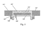
- the use of a latching connection shown in FIG Fig. 5 , has several other advantages.
- the light disk 102 'with integrated lighting unit 103', 104 ' can be inserted into the outer skin 101' at almost any point in the production process with little effort and / or temporarily removed therefrom. For example, the need to cover the lens 102 'in the case of painting the outer skin 101' can be avoided.
- the use of a locking connection the isolated replacement of the lens 102 'with integrated lighting unit 103', 104 'in the event of a defect or damage allows.
- the locking connection is according to Fig. 5 realized by the provision of at least one latching element 106 'on the lens 102' and a receptacle for receiving the latching element 106 'suitable recess 107' in the plastic of the outer skin.
- a detachable or non-detachable latching connection is achieved.
Landscapes
- Engineering & Computer Science (AREA)
- Mechanical Engineering (AREA)
- General Engineering & Computer Science (AREA)
- Non-Portable Lighting Devices Or Systems Thereof (AREA)
- Injection Moulding Of Plastics Or The Like (AREA)
Abstract
Claims (3)
- Feux de véhicule automobile intégrés dans la peau extérieure en matière plastique du véhicule comportant une plaque lumineuse (12) en matière plastique et un module de lumière (13, 14) installé derrière la surface supérieure du disque lumineux,• la plaque lumineuse étant intégrée par un procédé d'injection à plusieurs composants dans la pellicule extérieure (11) fabriquée en matière plastique d'un véhicule automobile,• le module de lumière étant enrobé au moins partiellement par une liaison par la forme dans la matière plastique de la plaque lumineuse comme résultant du procédé d'injection multi-composants en étant fixé solidairement en position sur la plaque lumineuse par l'enrobage,• le module de lumière est enveloppé par la matière plastique de la peau extérieure, en partie par une liaison par la forme comme résultant du procédé d'injection multi-composant.
- Feux de véhicule automobile, selon la revendication 1,
caractérisé en ce que
l'unité d'éclairage se compose d'au moins un support de circuit (13) et d'au moins un moyen d'éclairage (14) installé sur le support de circuit. - Feux de véhicule automobile, selon l'une des revendications 1 ou 2,
caractérisé en ce que
le module de lumière est enveloppé complètement par une liaison par la forme de la matière plastique de la plaque lumineuse.
Applications Claiming Priority (2)
| Application Number | Priority Date | Filing Date | Title |
|---|---|---|---|
| DE102004039004A DE102004039004A1 (de) | 2004-08-11 | 2004-08-11 | Kraftfahrzeugleuchte mit einer aus Kunststoff gefertigten Lichtscheibe |
| PCT/EP2005/007039 WO2006018067A1 (fr) | 2004-08-11 | 2005-06-30 | Bloc optique de vehicule a moteur dote d'un diffuseur en plastique |
Publications (2)
| Publication Number | Publication Date |
|---|---|
| EP1776255A1 EP1776255A1 (fr) | 2007-04-25 |
| EP1776255B1 true EP1776255B1 (fr) | 2011-10-26 |
Family
ID=34972246
Family Applications (1)
| Application Number | Title | Priority Date | Filing Date |
|---|---|---|---|
| EP05759140A Expired - Lifetime EP1776255B1 (fr) | 2004-08-11 | 2005-06-30 | Bloc optique de vehicule a moteur dote d'un diffuseur en plastique |
Country Status (6)
| Country | Link |
|---|---|
| US (1) | US7641371B2 (fr) |
| EP (1) | EP1776255B1 (fr) |
| JP (1) | JP4686545B2 (fr) |
| CN (1) | CN100593485C (fr) |
| DE (1) | DE102004039004A1 (fr) |
| WO (1) | WO2006018067A1 (fr) |
Families Citing this family (21)
| Publication number | Priority date | Publication date | Assignee | Title |
|---|---|---|---|---|
| DE502006000775D1 (de) * | 2005-02-11 | 2008-07-03 | Kompled Gmbh & Co Kg | Fahrzeugaussenleuchte und Verfahren zur Herstellung einer solchen Fahrzeugaussenleuchte |
| DE102006055996B4 (de) * | 2006-11-28 | 2019-05-16 | Bayerische Motoren Werke Aktiengesellschaft | Karosserieteil für ein Kraftfahrzeug |
| DE102007018985A1 (de) * | 2007-04-21 | 2008-10-23 | Hella Kgaa Hueck & Co. | Beleuchtungsvorrichtung für Fahrzeuge |
| FR2925417B1 (fr) * | 2007-12-21 | 2010-04-02 | Peugeot Citroen Automobiles Sa | Dispositif d'assemblage impliquant une glace de projecteur fixee a une piece de vehicule automobile, procedes et fabrication |
| DE102008019926B4 (de) | 2008-04-21 | 2011-07-07 | Fraunhofer-Gesellschaft zur Förderung der angewandten Forschung e.V., 80686 | Beleuchtungsvorrichtung und Verfahren zur Erzeugung einer flächigen Lichtausgabe |
| FR2933664B1 (fr) * | 2008-07-11 | 2011-04-22 | Peugeot Citroen Automobiles Sa | Element de carrosserie de vehicule automobile a ecran defini de bloc optique. |
| DE202009014012U1 (de) * | 2009-07-17 | 2009-12-31 | Hella Kgaa Hueck & Co. | Beleuchtungsvorrichtung für Fahrzeuge |
| DE102010043948A1 (de) * | 2010-11-16 | 2012-05-16 | Robert Bosch Gmbh | Verfahren zur Herstellung einer Mehrkomponenten-Spiegelvorrichtung |
| JP2014518437A (ja) * | 2011-06-28 | 2014-07-28 | フレクストロニクス オートモーティブ ゲゼルシャフト ミット ベシュレンクテル ハフツング ウント コンパニー コマンディートゲゼルシャフト | Ledランプ |
| DE102011119379A1 (de) * | 2011-11-25 | 2013-05-29 | Volkswagen Aktiengesellschaft | Beleuchtungsvorrichtung für ein Kraftfahrzeug |
| US9120517B2 (en) * | 2012-03-28 | 2015-09-01 | David Salvaggio, JR. | Carbon fiber shells for customizing the appearance of a vehicle |
| US11230338B2 (en) | 2012-03-28 | 2022-01-25 | Salvaggio Jr David | Integrated electronic component in vehicle body |
| DE102013216961B4 (de) | 2013-08-26 | 2023-08-10 | Ledvance Gmbh | Zusammenbau einer Halbleiterlampe aus separat hergestellten Bauteilen |
| EP3117141B1 (fr) | 2014-03-12 | 2019-05-08 | Volkswagen Aktiengesellschaft | Véhicule automobile et phare de véhicule automobile comprenant un boîtier d'adaptateur |
| US20170284623A1 (en) * | 2016-03-31 | 2017-10-05 | GM Global Technology Operations LLC | Methods and apparatus for free-form illumination assemblies |
| DE102016215579A1 (de) * | 2016-08-19 | 2018-02-22 | Bayerische Motoren Werke Aktiengesellschaft | Fahrzeug-Beleuchtungsvorrichtung mit OLED |
| EP3722065A1 (fr) | 2019-04-10 | 2020-10-14 | DURA Automotive Holdings U.K., Ltd. | Pièce de garniture de véhicule automobile et son procédé de fabrication |
| DE102019116364A1 (de) * | 2019-05-10 | 2020-11-12 | OSRAM CONTINENTAL GmbH | Fahrzeugbauteil, Fahrzeug und Verfahren |
| US12313234B2 (en) | 2019-12-25 | 2025-05-27 | Volvo Truck Corporation | Bumper lens unit of a vehicle |
| DE102021201145A1 (de) | 2021-02-08 | 2022-08-11 | Volkswagen Aktiengesellschaft | Kraftfahrzeugscheinwerfer und Verfahren zum Betrieb eines Kraftfahrzeugscheinwerfers |
| DE102021117675A1 (de) | 2021-07-08 | 2023-01-12 | Novem Car Interior Design Gmbh | Formteil und Verfahren zur Herstellung eines Formteils |
Family Cites Families (19)
| Publication number | Priority date | Publication date | Assignee | Title |
|---|---|---|---|---|
| GB2284306B (en) * | 1991-03-13 | 1995-10-11 | Standard Products Co | Electroluminescent light strip |
| JPH0817113B2 (ja) * | 1991-03-13 | 1996-02-21 | ザ スタンダード プロダクツ カンパニー | エレクトロルミネッセントライトストリップ |
| DE4223795A1 (de) * | 1992-07-20 | 1994-02-03 | Priesemuth W | Optoelektronisches Bauelement |
| EP0838367B1 (fr) * | 1996-10-23 | 2002-12-04 | Volkswagen Aktiengesellschaft | Feu ou phare de véhicule destiné à être fixé a une ou plusieures parties d'un véhicule |
| CN2280639Y (zh) * | 1996-12-30 | 1998-05-06 | 高连柱 | Led机动车指示灯 |
| DE19722614C2 (de) * | 1997-05-30 | 2002-02-07 | Kostal Leopold Gmbh & Co Kg | Ausleuchtungsvorrichtung für eine Anzeigeeinrichtung |
| CN2318081Y (zh) * | 1997-09-22 | 1999-05-12 | 黄世明 | 汽车后窗信号灯 |
| JP3442273B2 (ja) * | 1997-12-17 | 2003-09-02 | 株式会社日立製作所 | バスシステムおよび回路基板 |
| US6152590A (en) * | 1998-02-13 | 2000-11-28 | Donnelly Hohe Gmbh & Co. Kg | Lighting device for motor vehicles |
| DE19805771A1 (de) * | 1998-02-13 | 1999-08-19 | Hohe Gmbh & Co Kg | Beleuchtungseinrichtung für Kraftfahrzeuge |
| JP4132353B2 (ja) * | 1999-02-22 | 2008-08-13 | 株式会社小糸製作所 | 車輌灯具用レンズ |
| JP3896743B2 (ja) * | 1999-11-30 | 2007-03-22 | スズキ株式会社 | 車両用標識灯装置 |
| US20010053082A1 (en) * | 1999-12-22 | 2001-12-20 | Makarand H. Chipalkatti | Electroluminescent vehicle lamp |
| US6739733B1 (en) * | 2000-03-09 | 2004-05-25 | N.I.R., Inc. | LED lamp assembly |
| US6533444B2 (en) * | 2000-05-12 | 2003-03-18 | Wen I Auguste Lee | Lighting directional sign for vehicle signal light |
| DE10058658A1 (de) * | 2000-11-25 | 2002-05-29 | Volkswagen Ag | Dioden-Folien-Anordnung zur Beleuchtung |
| DE10228446A1 (de) * | 2002-06-26 | 2004-01-15 | Hella Kg Hueck & Co. | Anordnung mit elektrischen Bauteilen |
| DE10336615A1 (de) * | 2002-08-21 | 2005-03-03 | Mayr Tuning Gmbh | Leuchtköper-Einsatz zum nachträglichen Einbau in Standard-Fahrzeugseitenspiegel |
| DE20304930U1 (de) * | 2003-02-17 | 2003-08-07 | Aspöck Systems Ges.m.b.H., Peuerbach | Außenleuchte für Fahrzeuge |
-
2004
- 2004-08-11 DE DE102004039004A patent/DE102004039004A1/de not_active Withdrawn
-
2005
- 2005-06-30 JP JP2007525189A patent/JP4686545B2/ja not_active Expired - Fee Related
- 2005-06-30 CN CN200580022646A patent/CN100593485C/zh not_active Expired - Fee Related
- 2005-06-30 EP EP05759140A patent/EP1776255B1/fr not_active Expired - Lifetime
- 2005-06-30 WO PCT/EP2005/007039 patent/WO2006018067A1/fr not_active Ceased
-
2007
- 2007-01-24 US US11/657,050 patent/US7641371B2/en not_active Expired - Lifetime
Also Published As
| Publication number | Publication date |
|---|---|
| WO2006018067A1 (fr) | 2006-02-23 |
| CN1980814A (zh) | 2007-06-13 |
| US20080043483A1 (en) | 2008-02-21 |
| JP4686545B2 (ja) | 2011-05-25 |
| JP2008509535A (ja) | 2008-03-27 |
| US7641371B2 (en) | 2010-01-05 |
| DE102004039004A1 (de) | 2006-02-23 |
| EP1776255A1 (fr) | 2007-04-25 |
| CN100593485C (zh) | 2010-03-10 |
Similar Documents
| Publication | Publication Date | Title |
|---|---|---|
| EP1776255B1 (fr) | Bloc optique de vehicule a moteur dote d'un diffuseur en plastique | |
| EP2363324B1 (fr) | Bandeau enjoliveur éclairé | |
| EP2726784B1 (fr) | Système d'éclairage muni d'une matière d'étanchéité et de scellement | |
| DE102011017162B4 (de) | Explosionsgeschütztes LED-Modul | |
| EP3825601B1 (fr) | Élément lumineux pour un véhicule automobile et véhicule automobile | |
| EP3421278B1 (fr) | Enjoliveur éclairé | |
| EP1852306B1 (fr) | Eclairage doté d'au moins une unité d'élément lumineux pour véhicules, de préférence pour véhicules automobiles | |
| DE102008042330A1 (de) | Beleuchtete Griffanordnung für ein Kraftfahrzeug | |
| EP2525138B1 (fr) | Phare de véhicule automobile et son procédé de fabrication | |
| EP3210444B1 (fr) | Appareil d'éclairage extérieur pour véhicule automobile | |
| DE10129021A1 (de) | Leuchteinrichtung für ein Fahrzeug | |
| EP3727073B1 (fr) | Boucle de ceinture éclairée pour système de ceinture de sécurité d'un véhicule automobile | |
| EP1655174A2 (fr) | Dispositif d'éclairage pour un vehicule | |
| DE10341572B4 (de) | Fahrzeugleuchte mit Elektrolumineszenz-Anordnung | |
| EP2014973B1 (fr) | Eclairage | |
| EP2131101A1 (fr) | Lampe | |
| WO2017216019A1 (fr) | Feu de véhicules | |
| EP3037721A1 (fr) | Dispositif d'éclairage commandé par capteur | |
| DE102020201645A1 (de) | Beleuchtungsvorrichtung für ein Kraftfahrzeug | |
| AT517467B1 (de) | Lagereinrichtung für flächige Leuchten | |
| EP2353936A1 (fr) | Ensemble de moyen d'éclairage et éclairage pour un véhicule utilitaire | |
| AT521023B1 (de) | Zierleiste | |
| DE102008004483A1 (de) | Flexible Leuchtmittelbaugruppe für Fahrzeugleuchten | |
| DE102017100606A1 (de) | Leuchte für Fahrzeuge | |
| EP2395281B1 (fr) | Lampe de véhicule automobile |
Legal Events
| Date | Code | Title | Description |
|---|---|---|---|
| PUAI | Public reference made under article 153(3) epc to a published international application that has entered the european phase |
Free format text: ORIGINAL CODE: 0009012 |
|
| 17P | Request for examination filed |
Effective date: 20061116 |
|
| AK | Designated contracting states |
Kind code of ref document: A1 Designated state(s): DE ES FR GB IT SE |
|
| DAX | Request for extension of the european patent (deleted) | ||
| RBV | Designated contracting states (corrected) |
Designated state(s): DE ES FR GB IT SE |
|
| 17Q | First examination report despatched |
Effective date: 20090127 |
|
| GRAP | Despatch of communication of intention to grant a patent |
Free format text: ORIGINAL CODE: EPIDOSNIGR1 |
|
| GRAS | Grant fee paid |
Free format text: ORIGINAL CODE: EPIDOSNIGR3 |
|
| GRAA | (expected) grant |
Free format text: ORIGINAL CODE: 0009210 |
|
| AK | Designated contracting states |
Kind code of ref document: B1 Designated state(s): DE ES FR GB IT SE |
|
| REG | Reference to a national code |
Ref country code: GB Ref legal event code: FG4D Free format text: NOT ENGLISH |
|
| REG | Reference to a national code |
Ref country code: DE Ref legal event code: R096 Ref document number: 502005012075 Country of ref document: DE Effective date: 20111229 |
|
| PG25 | Lapsed in a contracting state [announced via postgrant information from national office to epo] |
Ref country code: SE Free format text: LAPSE BECAUSE OF FAILURE TO SUBMIT A TRANSLATION OF THE DESCRIPTION OR TO PAY THE FEE WITHIN THE PRESCRIBED TIME-LIMIT Effective date: 20111026 |
|
| PLBE | No opposition filed within time limit |
Free format text: ORIGINAL CODE: 0009261 |
|
| STAA | Information on the status of an ep patent application or granted ep patent |
Free format text: STATUS: NO OPPOSITION FILED WITHIN TIME LIMIT |
|
| PGFP | Annual fee paid to national office [announced via postgrant information from national office to epo] |
Ref country code: IT Payment date: 20120626 Year of fee payment: 8 |
|
| 26N | No opposition filed |
Effective date: 20120727 |
|
| REG | Reference to a national code |
Ref country code: DE Ref legal event code: R097 Ref document number: 502005012075 Country of ref document: DE Effective date: 20120727 |
|
| PG25 | Lapsed in a contracting state [announced via postgrant information from national office to epo] |
Ref country code: ES Free format text: LAPSE BECAUSE OF FAILURE TO SUBMIT A TRANSLATION OF THE DESCRIPTION OR TO PAY THE FEE WITHIN THE PRESCRIBED TIME-LIMIT Effective date: 20120206 |
|
| PG25 | Lapsed in a contracting state [announced via postgrant information from national office to epo] |
Ref country code: IT Free format text: LAPSE BECAUSE OF NON-PAYMENT OF DUE FEES Effective date: 20130630 |
|
| PGFP | Annual fee paid to national office [announced via postgrant information from national office to epo] |
Ref country code: GB Payment date: 20140626 Year of fee payment: 10 |
|
| PGFP | Annual fee paid to national office [announced via postgrant information from national office to epo] |
Ref country code: FR Payment date: 20140630 Year of fee payment: 10 |
|
| GBPC | Gb: european patent ceased through non-payment of renewal fee |
Effective date: 20150630 |
|
| REG | Reference to a national code |
Ref country code: FR Ref legal event code: ST Effective date: 20160229 |
|
| PG25 | Lapsed in a contracting state [announced via postgrant information from national office to epo] |
Ref country code: GB Free format text: LAPSE BECAUSE OF NON-PAYMENT OF DUE FEES Effective date: 20150630 |
|
| PG25 | Lapsed in a contracting state [announced via postgrant information from national office to epo] |
Ref country code: FR Free format text: LAPSE BECAUSE OF NON-PAYMENT OF DUE FEES Effective date: 20150630 |
|
| P01 | Opt-out of the competence of the unified patent court (upc) registered |
Effective date: 20230502 |
|
| PGFP | Annual fee paid to national office [announced via postgrant information from national office to epo] |
Ref country code: DE Payment date: 20240605 Year of fee payment: 20 |
|
| REG | Reference to a national code |
Ref country code: DE Ref legal event code: R071 Ref document number: 502005012075 Country of ref document: DE |