EP1777100B1 - Lehnenanordnung - Google Patents
Lehnenanordnung Download PDFInfo
- Publication number
- EP1777100B1 EP1777100B1 EP06019586A EP06019586A EP1777100B1 EP 1777100 B1 EP1777100 B1 EP 1777100B1 EP 06019586 A EP06019586 A EP 06019586A EP 06019586 A EP06019586 A EP 06019586A EP 1777100 B1 EP1777100 B1 EP 1777100B1
- Authority
- EP
- European Patent Office
- Prior art keywords
- backrest
- vehicle
- arrangement
- rail
- wheelchair
- Prior art date
- Legal status (The legal status is an assumption and is not a legal conclusion. Google has not performed a legal analysis and makes no representation as to the accuracy of the status listed.)
- Active
Links
Images






Classifications
-
- A—HUMAN NECESSITIES
- A61—MEDICAL OR VETERINARY SCIENCE; HYGIENE
- A61G—TRANSPORT, PERSONAL CONVEYANCES, OR ACCOMMODATION SPECIALLY ADAPTED FOR PATIENTS OR DISABLED PERSONS; OPERATING TABLES OR CHAIRS; CHAIRS FOR DENTISTRY; FUNERAL DEVICES
- A61G3/00—Ambulance aspects of vehicles; Vehicles with special provisions for transporting patients or disabled persons, or their personal conveyances, e.g. for facilitating access of, or for loading, wheelchairs
- A61G3/08—Accommodating or securing wheelchairs or stretchers
- A61G3/0808—Accommodating or securing wheelchairs
-
- B—PERFORMING OPERATIONS; TRANSPORTING
- B60—VEHICLES IN GENERAL
- B60N—SEATS SPECIALLY ADAPTED FOR VEHICLES; VEHICLE PASSENGER ACCOMMODATION NOT OTHERWISE PROVIDED FOR
- B60N2/00—Seats specially adapted for vehicles; Arrangement or mounting of seats in vehicles
- B60N2/02—Seats specially adapted for vehicles; Arrangement or mounting of seats in vehicles the seat or part thereof being movable, e.g. adjustable
- B60N2/04—Seats specially adapted for vehicles; Arrangement or mounting of seats in vehicles the seat or part thereof being movable, e.g. adjustable the whole seat being movable
- B60N2/06—Seats specially adapted for vehicles; Arrangement or mounting of seats in vehicles the seat or part thereof being movable, e.g. adjustable the whole seat being movable slidable
-
- B—PERFORMING OPERATIONS; TRANSPORTING
- B60—VEHICLES IN GENERAL
- B60N—SEATS SPECIALLY ADAPTED FOR VEHICLES; VEHICLE PASSENGER ACCOMMODATION NOT OTHERWISE PROVIDED FOR
- B60N2/00—Seats specially adapted for vehicles; Arrangement or mounting of seats in vehicles
- B60N2/02—Seats specially adapted for vehicles; Arrangement or mounting of seats in vehicles the seat or part thereof being movable, e.g. adjustable
- B60N2/04—Seats specially adapted for vehicles; Arrangement or mounting of seats in vehicles the seat or part thereof being movable, e.g. adjustable the whole seat being movable
- B60N2/06—Seats specially adapted for vehicles; Arrangement or mounting of seats in vehicles the seat or part thereof being movable, e.g. adjustable the whole seat being movable slidable
- B60N2/07—Slide construction
- B60N2/0735—Position and orientation of the slide as a whole
-
- B—PERFORMING OPERATIONS; TRANSPORTING
- B60—VEHICLES IN GENERAL
- B60N—SEATS SPECIALLY ADAPTED FOR VEHICLES; VEHICLE PASSENGER ACCOMMODATION NOT OTHERWISE PROVIDED FOR
- B60N2/00—Seats specially adapted for vehicles; Arrangement or mounting of seats in vehicles
- B60N2/24—Seats specially adapted for vehicles; Arrangement or mounting of seats in vehicles for particular purposes or particular vehicles
- B60N2/245—Seats specially adapted for vehicles; Arrangement or mounting of seats in vehicles for particular purposes or particular vehicles for handicapped persons
-
- B—PERFORMING OPERATIONS; TRANSPORTING
- B60—VEHICLES IN GENERAL
- B60N—SEATS SPECIALLY ADAPTED FOR VEHICLES; VEHICLE PASSENGER ACCOMMODATION NOT OTHERWISE PROVIDED FOR
- B60N2/00—Seats specially adapted for vehicles; Arrangement or mounting of seats in vehicles
- B60N2/24—Seats specially adapted for vehicles; Arrangement or mounting of seats in vehicles for particular purposes or particular vehicles
- B60N2/30—Non-dismountable or dismountable seats storable in a non-use position, e.g. foldable spare seats
- B60N2/3002—Non-dismountable or dismountable seats storable in a non-use position, e.g. foldable spare seats back-rest movements
- B60N2/3004—Non-dismountable or dismountable seats storable in a non-use position, e.g. foldable spare seats back-rest movements by rotation only
- B60N2/3018—Non-dismountable or dismountable seats storable in a non-use position, e.g. foldable spare seats back-rest movements by rotation only about vertical axis
-
- B—PERFORMING OPERATIONS; TRANSPORTING
- B60—VEHICLES IN GENERAL
- B60N—SEATS SPECIALLY ADAPTED FOR VEHICLES; VEHICLE PASSENGER ACCOMMODATION NOT OTHERWISE PROVIDED FOR
- B60N2/00—Seats specially adapted for vehicles; Arrangement or mounting of seats in vehicles
- B60N2/24—Seats specially adapted for vehicles; Arrangement or mounting of seats in vehicles for particular purposes or particular vehicles
- B60N2/30—Non-dismountable or dismountable seats storable in a non-use position, e.g. foldable spare seats
- B60N2/3038—Cushion movements
- B60N2/304—Cushion movements by rotation only
- B60N2/3045—Cushion movements by rotation only about transversal axis
-
- B—PERFORMING OPERATIONS; TRANSPORTING
- B60—VEHICLES IN GENERAL
- B60N—SEATS SPECIALLY ADAPTED FOR VEHICLES; VEHICLE PASSENGER ACCOMMODATION NOT OTHERWISE PROVIDED FOR
- B60N2/00—Seats specially adapted for vehicles; Arrangement or mounting of seats in vehicles
- B60N2/24—Seats specially adapted for vehicles; Arrangement or mounting of seats in vehicles for particular purposes or particular vehicles
- B60N2/30—Non-dismountable or dismountable seats storable in a non-use position, e.g. foldable spare seats
- B60N2/3038—Cushion movements
- B60N2/304—Cushion movements by rotation only
- B60N2/3052—Cushion movements by rotation only about vertical axis
Definitions
- the invention relates to a backrest assembly for installation in a vehicle, in particular in a motor vehicle, for the transport of persons, in particular wheelchair users.
- a wheelchair user for this purpose is pushed in his wheelchair in a correspondingly large motor vehicle, for example by means of a ramp or a lifting device and secured there against slipping.
- a seat belt which is designed as a lap belt, prevent slipping out of the wheelchair user from his wheelchair.
- a backrest for insertion is known.
- Such a backrest is inserted into the floor of the vehicle behind the respective wheelchair with wheelchair users, and the wheelchair immediately before arranged and fixed.
- the inserted backrest can thus support the back and head of the person sitting in his wheelchair wheelchair user.
- the backrest is formed together with the seat part pivotable about an approximately vertical axis. It is provided here that a folding up of the seat surface of the seat activates a spring which pivots the folded-up seat together with the associated backrest about the mentioned vertical axis from the operating position into a rest position in a lateral recess. To secure wheelchair users in a motor vehicle, such a construction is neither intended nor suitable.
- the DE 35 21 233 A1 describes a backrest for a rear seat, for example in a patient transport vehicle.
- the backrest can be pivoted about a vertical axis from a rest position, in which it is arranged approximately parallel to the vehicle side wall, in an operating position oriented at about 90 ° to it; There, the backrest is locked by means of a locking device on a running below the swung-out backrest support profile.
- This construction is neither intended nor suitable for supporting a wheelchair user.
- DE 34 47 780 A1 a device with which a wheelchair can be fixed in a motor vehicle.
- a seat belt may be attached to the device.
- this known device but also not thought or suitable.
- the invention is therefore based on the object to facilitate the transport of wheelchair users and to realize the highest possible level of safety.
- a backrest assembly for installation in a motor vehicle for the transport of wheelchair users with a backrest for supporting a wheelchair user standing in front in the direction of travel, which is pivotally connected to the vehicle about a first vertical pivot axis proposed.
- a connection takes place, for example, on a vehicle interior wall.
- the backrest from a stowed position in which the backrest is located on the side wall of the motor vehicle are pivoted to a supporting position in which the backrest is arranged approximately transversely to the side wall.
- the stowed position is in this case arranged from the support position to the rear, so that the backrest is pivoted when pivoting from the stowed position in the support position substantially to vome.
- the backrest When the backrest is in a stowed position there is room to drive in or out of a wheelchair. If a wheelchair is parked in a transport position in the motor vehicle, the backrest can be easily folded from the stowed position from behind against the back of the wheelchair in the sitting position and locked there. As a result, a support of the back of the wheelchair user is possible in a simple manner.
- the backrest preferably has a headrest. Such a headrest can be adjusted relative to the backrest, in particular be arranged adjustable in height. Furthermore, it is also possible to carry out the backrest together with the headrest in one-piece connection,
- a safety belt is provided, which is at least partially attached to the backrest.
- a three-point belt into consideration which is fixed with two points, for example, to the backrest in the region of the vertical pivot axis or on the side wall.
- the buckle is then arranged on the side facing away from the vertical pivot axis of the backrest.
- a fastening is to be considered, which acts on a possible support frame of the backrest.
- the backrest arrangement is characterized in that a seat portion is provided, which is pivotally connected to the vehicle about a horizontal pivot axis and the backrest and the seat portion are pivotally independent of each other.
- the seat portion can in this case be pivoted from a stowed position into a sitting position. This will allow that too the backrest can be provided in a supporting position a seat portion, thereby providing the further possibility to be able to carry a person without a wheelchair.
- a seat belt which is at least partially fastened to the backrest can also be used in this case for a person sitting on the seat section.
- the horizontal pivot axis about a second vertical pivot axis is pivotally connected to the vehicle.
- To move the seat portion of the sitting position in the stowed position of this is first folded around the horizontal pivot axis up in a vertical position and then pivoted together with the horizontal pivot axis about a second vertical pivot axis with its underside to the vehicle side wall to which it is attached.
- Through this combined pivoting movement is achieved that has a seat cushion of the seat portion in the stowed position to the vehicle interior. Any injury-critical elements on the underside of the seat portion are thus difficult to reach in the stowed position from the interior and thus from carried persons, thereby reducing any risk of injury. This is especially important when transporting a wheelchair user.
- the backrest is in its supporting position and the seat portion in its stowed position.
- the wheelchair user is in front of the backrest in support position and the seat portion in the stowed position, which points with its upholstery side to the wheelchair user.
- first and the second vertical pivot axis are arranged parallel to each other. Both vertical pivot axes can also fall together.
- the backrest assembly is characterized in that the backrest and / or the seat portion is connectable by means of a support structure to a fastening device with the vehicle.
- the support structure in this case carries the backrest and / or the seat portion including the respective pivot mechanisms, the fastening device is firmly connected to a side wall of the vehicle, for example via a bond.
- the support structure and the fastening device are adapted for connection with each other.
- the support structure can thus be connected to the fastening device and thus to the vehicle.
- the fact that the support structure and the fastening device are adapted to each other, a connection between them is possible in a simple manner, which may for example also allow a change in the mounting position of the support structure.
- the fastening device has at least one rail
- the carrier with at least one slide bearing with the at least one rail in particular in the direction of travel of the vehicle, is slidably connectable.
- the position of a backrest assembly and thus the sitting position of a wheelchair user or a person without a wheelchair sitting on a seat portion can be changed in a simple manner, in particular in the direction of travel of the vehicle.
- it can be responded to a changed need for legroom or storage space.
- a plurality of backrest arrangements with a variable distance can be positioned behind one another.
- the support structure has for this purpose at least one slider which slides in a rail in the longitudinal direction of the rail.
- two parallel rails may be provided, in each of which a slider for moving in the longitudinal direction of the rails is used and fixed to the support structure.
- the support structure can also connect a backrest and a seat portion together with the construction for the pivot axis or the pivot axes against each other movable and fasten together to the fastening device. It is advantageous if the first and the second vertical pivot axis coincide, although the backrest and the seat portion are independently pivotable about this common vertical axis.
- a slider of a rail is preferably included such that it can only be moved in the longitudinal direction of the rail.
- the rail also prevents the jumping out of a slider.
- the arrangement of a slider within a rail takes place, for example, so that the slider only along one narrow strip protrudes in the longitudinal direction of the rail from this for connection to the support structure. Damage risks, such as the risk of pinching fingers between a rail and a slider, are thereby reduced as compared to rails in which the slider runs on the outside.
- At least one of the sliders has at least one roller for rolling the slider in the rail and / or at least one sliding block, in particular a safety block for preventing slipping out of the rail in a direction transverse to the longitudinal direction of the rail.
- rollers are provided to allow easy movement of the slider along the respective rail.
- high demands are placed on the stability of the connection between the support structure and the rail (s). The high requirements arise from the fact that even in the case of a traffic accident in which very high forces between individual connected elements can occur, the support structure should not jump out of their rail or their rails. Such a high requirement for stability is not achievable by rolling alone, so that one or more sliding blocks are provided to increase the stability.
- the backrest assembly Since a change in position of the backrest assembly is often made only rarely, can be dispensed with roles sometimes.
- not every glider includes stabilizing sliding blocks.
- the sliders can also be designed so that they are guided only by rollers, and further sliding blocks are designed as safety stones, which develop their effect only in the event of an incident and prevent slipping out of a rail.
- the leaning arrangement is characterized in that two rails are provided, each with a slider and one of the slider at least one roller and the other slider has at least one sliding block.
- the backrest assembly is characterized in that the at least one rail has grids for fixing each of a slider in predetermined by the screening positions.
- a grid can be provided for example by a plurality of holes which are formed transversely to the rail longitudinal direction and in which engages to reach a fixed position, at least one pin of a slider.
- a plurality of notches are listed, in which engages for example on the part of the slider adapted to the respective notch nose,
- the rail or the rails for fixing the backrest assembly in the intended state are arranged parallel to a vehicle floor and extending obliquely or horizontally on the vehicle side wall.
- a horizontal arrangement of the vehicle rails also assumes a horizontal arrangement of the rails.
- the backrest assembly along the vehicle side wall can be arranged and fixed in different positions.
- the backrest arrangement preferably has at least one vertical column for pivoting the backrest arrangement or a part thereof.
- the vertical column coincides with a vertical pivot axis.
- the column can be attached to one or more rails an.der vehicle side wall.
- the vertical column in the horizontal direction, in particular in the direction of travel of the vehicle along the side wall can be displaced, whereby the position of the backrest assembly can be changed within the vehicle, a stable attachment of the backrest assembly is this while flexible with respect to the position of the backrest assembly in the vehicle possible.
- the floor in the vehicle requires no change for the arrangement of one or more backrest arrangements. For example, it may be flat to allow for easy sliding of a wheelchair. Also, no fastening devices in the ground are necessary, which would make it difficult, for example, a floor cleaning otherwise.
- the backrest assembly is designed so that the backrest is selectively pivotable in relation to the direction of travel of the vehicle in each case in a front and a rear stowed position on the side wall.
- the backrest or headrest After being pushed in from behind, the backrest or headrest can then be swiveled from the rear stowage position directly to the back of the wheelchair user and locked there. In other. Situations where, for example, no wheelchair users but bulky items to be transported, it may be convenient to pivot the backrest in its front stowed position. In this case, any padding of the backrest to the vehicle wall and is thus facing away from the cargo space. The cargo can not pollute or damage the upholstery in this case. Incidentally, it may happen that far back of the vehicle arranged and also pivoted backwards headrests or backrests oppose the closing of a rear door.
- the backrest is pivotable about a horizontal functional axis.
- the backrest preferably has an elongated support surface for supporting the wheelchair user standing in front of it.
- the functional axis runs perpendicular to the support surface and eccentrically thereto. That is, it runs outside the center of the support surface. Preferably, it is arranged at a further distance from the vertical pivot axis than this center.
- Such an elongated support surface may for example be a non-square, substantially rectangular support surface.
- Such a support surface is designed to be perpendicular and points to a person sitting in front of it. The surface is regularly provided with a cushion.
- a pivoting position in a pivoting position, it has a large extent in the horizontal direction and a small extent in the vertical direction.
- it is to be used in particular as a headrest for a non-wheelchair driver and arranged according to head height of a seated person. Is such a long in the horizontal direction trained backrest pivoted about the horizontal, perpendicular to its extending functional axis by 90 °, it stands then vertically.
- this pivoting position it has a large extent in the vertical direction and a small extent in the horizontal direction, with the support surface still facing the person in front, namely in the direction of travel.
- a vertical, narrow backrest can also be pivoted upwards by 90 ° upwards into a headrest.
- the backrest is pivotally mounted by means of an arm on the fastening device, in particular on the or a vertical column.
- an arm By using an arm, the distance of the backrest from the vehicle side wall can be determined. It is favorable if the arm is extendable. As a result, the distance between the backrest to the fastening device, in particular to the vertical column can be specified and also changed. The distance from the column can also assume different values in the support position and in the stowed position.
- the backrest in its supporting position from the side wall protrude far into the vehicle interior with the arm extended, whereas they can be accommodated as compact as possible in the stowed position when pushed together arm.
- the arm for example, designed as a telescopic arm, or the arm can be pulled out, for example, from a holder on the column or from a holder on the backrest. All these and other embodiments are to be understood according to the invention as an exemplary embodiments of an extendable arm.
- At least one vertical pillar carries a seat consisting of the seat portion and the backrest, and in addition a separately pivotable backrest.
- a seat is provided with seat portion and backrest seat for a passenger without a wheelchair. He can use the separately pivoting backrest as a headrest.
- the seat consisting of seat section and backrest seat can be pivoted to the vehicle side wall.
- the backrest assembly is preferably designed so that from a working position out in a first step, the seat portion about a horizontal axis against the backrest folding and in a second step, the backrest together with the seat portion about a vertical axis, in particular about a vertical column to the Vehicle side wall is pivotable.
- the remaining seat back may now be used to support him while seated in his wheelchair.
- the remaining backrest is pivoted about a horizontal functional axis so that it then stands vertically and acts as a backrest for the wheelchair user.
- this invention can be pushed with his wheelchair in a vehicle equipped with the invention, for this purpose, a backrest according to the invention is pivoted to the rear in a stowed position to pass with the wheelchair user. After the wheelchair user has reached his position, the backrest is pivoted from the back to his head and back and locked there so that they can not swing back into the stowed position.
- the wheelchair user is now basically supported to the rear.
- additional security measures can be taken, such as the use of a safety belt.
- a seat belt may also be provided according to the invention on the backrest assembly.
- a backrest after being pivoted from behind to the head of the wheelchair user about a vertical axis was pivoted about a horizontal, a cushion plane of the backrest cutting functional axis so that the headrest is now better as a backrest and can support both the head and a part of the back.
- a vehicle is equipped at least with a backrest assembly according to the invention.
- This includes conventional vehicles as well as electric vehicles.
- Another embodiment comprises a vehicle, which is characterized in that a plurality of Lehnan angelen are provided with two rails, each with a slider whose support structure engage in at least two common rails (are guided).
- the backrest assembly 1 of Fig. 1 has two backrests 2, each with a headrest 3 and a seat belt 4. Both backrests 2 are in a supporting position and are fixed to an upper and a lower rail 5, 6. The upper and lower rails 5, 6 are in turn fastened to a vehicle side wall 7 and extend in the direction of travel of the vehicle, on whose side wall 7 they are attached.
- a seat portion 8 is arranged in a sitting position.
- the seat portion 8 is pivotable about the horizontal axis 9, which runs into the plane of the drawing, in the direction of the backrest 2.
- This front seat back 2 is shown together with its seat portion 8 in a position for carrying a person without a wheelchair,
- right rear seat back 2 is a wheelchair user 10 with wheelchair 11 with large and small wheels 12, 13.
- This rear seat back 2 supports together with the headrest 3, the wheelchair user 10 in particular in the region of his head to the rear.
- the wheelchair user 10 sits in his wheelchair 11 and is secured by the seat belt 4.
- the position of the rear seat portion 8 is here in accordance with the plan view Fig. 2 to recognize. Accordingly, the rear seat portion 8 is to the vehicle side wall Pivoted away so that it is in its stowed position and facing with his upholstery side 14 to the wheelchair 10.
- the upholstered side 14 a pivot arm 15 is disposed on the seat portion 8 which is pivotally mounted about the common pivot axis 16 on the motor vehicle side wall 7. In this vertical pivot axis 16, the first vertical pivot axis of the backrest coincide with the second vertical pivot axis of the seat portion 8.
- the backrest 2 with its headrest 3 is about a further pivot arm 17 in the horizontal direction, in particular from the wheelchair user 10 to the vehicle side wall 7 about the common axis 16 pivotally.
- the front backrest 2 with its headrest 3 is located immediately behind the front seat portion in the supporting position.
- the pivot arms 15 and 17 of the seat portion 8 and the backrest 2 are arranged approximately parallel to each other in this sitting position for a person without a wheelchair.
- the seat portion 8 is folded for sitting in a horizontal position and has with its cushion side 14 upwards, and thus out of the plane.
- Both seat sections 8 and both backrests 2 with headrests 3 in their stowed position Both the seat portion 8 and the backrest 2 are in this position close to the vehicle side wall 7, and thereby leave a lot of space in the interior of the vehicle, which can be used, for example, for driving in or driving out a wheelchair user.
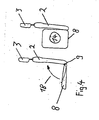
- Fig. 4 is illustratively the backrest assembly 1 shown with a seat portion 8 in the sitting position and another seat portion 8 in stowed position.
- the backrest 2 with the headrest 3 is located in both representations of Fig. 4 in their support position.
- the seat portion 8 is first to be folded along the marked folding arrow 18 about the horizontal pivot axis 9 to the backrest 2.
- the seat portion 8 is then arranged approximately plane-parallel to the backrest 2. From this intermediate position, the pivoting of the seat portion 8 takes place to a possible vehicle side wall until the right part of the Fig. 4 shown position is taken in which the pad side 14 of the same in the installed state in a vehicle to the interior.
- Fig. 5 shows a pivot arm 15 for the seat portion 8 and an upper and a lower pivot arm 17, 19 for the backrest 2 with the headrest 3.
- the three pivot arms 15, 17 and 19 are connected to a vertical support 20 as part of a support structure 24.
- the vertical support 20 is inserted via an upper and a lower slider in the upper or lower rail 5, 6 and thereby displaced in the direction of travel and the direction of travel of the vehicle, ie in the plane of the drawing or out of the plane.
- the lower slider 22 has a spacer portion 23 to achieve a vertical arrangement of the vertical beam 20.
- the safety belt 4 shown in dashed lines is fastened with an upper end 25 on the vertical support 20 and with its lower end 26 on the backrest 2.
- the buckle 27 is also attached to the backrest 2.
- the backrest assembly 1 In the backrest assembly 1 according to Fig. 5 is the backrest 2 in the supporting position and the seat portion 8 in the sitting position.
- the seat portion 8 In order to position a wheelchair in front of the backrest 2, the seat portion 8 must be brought into its stowed position. This is done by a combined pivotal movement about the horizontal pivot axis 9, which extends along the pivot arm 15, and the common pivot axis 16 which extends in the vertical support 20.
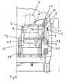
- the Fig. 6 now shows the seat portion 8 in its stowed position.
- the backrest 2 is in the supporting position and in front of the backrest 2 a wheelchair 10 is now arranged.
- the seat belt 4 is opposite to the arrangement according to Fig. 5 remained in his position. For buckling a person in the wheelchair 10, the seat belt 4 needs only to be guided around the wheelchair and the person sitting therein.
- FIG. 6 shows that the lower pivot arm 19 is disposed substantially above the large wheels 12 of the wheelchair 11.
- the backrest 2 thus extends in the horizontal direction to the back of a person sitting in the wheelchair 11 and accordingly the headrest 3 extends in a horizontal direction up to the person's head.
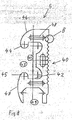
- the lower rail 6 is designed as a hollow profile with a mounting surface 30 for bonding the rail 6 with a motor vehicle side wall.
- the lower rail 6 has a sliding space 31 for receiving a slider 22.
- the lower rail 6 has a support surface 32 on which rollers of a slider can run.
- a connection between an inserted slider and a support structure, an opening 33 is provided, which is arranged between a first and a second nose 34, 35.
- the two lugs 34, 35 enclose the sliding space 31 in such a way that a slider can not slip out of the lower rail through the opening 33.
- On the second nose 35 a role is carried out as intended.
- the lower rail 6 is at its upper and lower to the passenger compartment facing surface 36, 37 designed round to avoid hazards such as sharp edges. In addition, a pleasing appearance can be achieved through the round design.
- To Gevvichtseinsparung recesses 38 are provided.
- the openings 39 are designed for fastening a vehicle interior trim.
- the upper rail 5 is designed as a hollow profile with a mounting surface 40 for bonding to a side wall.
- the sliding space 41 is adapted to the shape of a slider 21 for guiding a sliding block formed as a safety stone.
- a support surface 42 is provided to alternatively guide a roller.
- the opening 43 is predetermined by the first and second lugs 44, 45.
- the upper rail 5 has a round upper and lower surface 46, 47 and recesses 48 are provided for weight saving.
- the upper rail 5 Opposite the lower rail 6, the upper rail 5 in addition to a downwardly facing opening 49, in which a role of a slider is to lead.
- a guide of the support structure is thus carried out by rolling in the lower rail 6 and the opening 49 of the upper rail 5.
- a security stone is additionally guided in the sliding space 41 of the upper rail 5.
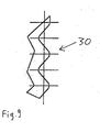
- the Fig. 9 shows an enlargement of the section A of Fig. 7 . From this enlarged view, it is clear that the fastening surface 30 has a greatly enlarged surface due to its approximately wave-shaped configuration, which leads to a higher strength in its bonding to a motor vehicle side wall 7.
- the magnification according to Fig. 9 also corresponds to an enlargement of the section B of the Fig. 8 , The wave-shaped configuration of the attachment surface 30 or 40 thus increases the adhesive properties.
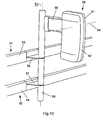
- FIG. 10 For example, an upper rail 51 and a lower rail 52 are shown, each having a lining 53 and 54.
- a vertical column 55 is attached via two attachment portions 56 and 57.
- the attachment portions 56 and 57 support the pillar 55 in the rails 51 and 52, with the attachment portions 56, 57 fixedly secured in the rails 51, 52, but which can be released to change their position along the rails 51, 52.
- an arm 58 is arranged, which carries the backrest 59.
- the arm 58 is pivotable together with the backrest 59 about the column 55 and thus about a vertical pivot axis 70 against a vehicle side wall 60.
- the backrest 59 shows the backrest 59 in its supporting position in which it projects transversely with the arm 58 to the vehicle side wall 60 and projects into the vehicle interior.
- the backrest 59 has a rear shell 61 and a pad 62 disposed therein.
- the pad 62 has a support surface 63 which is placed behind a wheelchair user, according to her FIG. 10 upper area behind the head of the wheelchair user and the lower area is placed behind the back of the wheelchair user and supports the body parts mentioned.
- a horizontal functional axis 64 is shown by dashed lines. This horizontal axis of action is perpendicular to the support surface 63.
- the intersection is approximately in the middle of the interface between the arm 58 and the backrest 59. This intersection is thus approximately in the middle of according to FIG. 10 Upper half of the support surface 63.
- a pivoting back of the backrest 59 by 90 ° about the horizontal functional axis 64 would lead to a concealment of the in FIG. 10 visible portion of the arm 58 lead.
- FIG. 11 shows the backrest 59 in its front stowed position, wherein the backrest 59 in this case is formed substantially horizontally. That is, compared to FIG. 10 the backrest 59 is pivoted by 90 ° about the horizontal functional axis 64. In this position, the backrest 59 acts only as a headrest. It is in this case substantially parallel to the arm 58 and thereby arranged in front of the arm 58 from the viewpoint of the pad 62.
- the arm 58 is pivotally connected via a pivot portion 65 to the column 55 and thus pivotable about the vertical axis 70.
- the backrest 59 is shown in its rear stowed position.
- the rear shell 61 in this case has the vehicle side wall 60 and the pad 62 with its support surface 63 to the vehicle interior.
- the backrest 59 according to the FIG. 12 is compared to FIG. 10 rotated by 90 ° about the horizontal functional axis 64.
- FIG. 13 shows a seat 66 having a seat portion 67 and a back seat back 68.
- the seat 66 is attached to the pillar 55 via the backrest 68.
- the seat 66 In the connecting region of the backrest 68 and the seat section 67, the seat 66 has a horizontal pivot axis 71 around which the seat section 67 can be folded against the backrest seat 68.
- the seat 67 is held firmly in this connection region by the backrest 68.
- a seatbelt buckle 69 for a safety belt is also shown.
- the separate backrest 59 is still available as a supplement to the seat 66. It acts as a headrest here.
- the backrest 59 is separated from the seat 66 and the Pillar 55 attached by means of arm 58 and about this independently of the seat 66 pivotally. Despite the separate pivoting of the backrest 59 and seat 66 together form a seat unit with a seat portion 67, a back seat backrest 68 and another backrest 59 as a headrest.
- This seat assembly is intended for a person without a wheelchair.
- the seat portion 67 is to fold against the backrest seat 68 about the horizontal axis 71 in the region of the buckle 69 and the back seat backrest 68 together with the seat portion 67 then pivot about the vertical column 55 against the vehicle side wall 60 , Thereafter, the backrest 59 remains in its illustrated position.
- it is about 90 ° about the horizontal axis of action 64 with the im in accordance with FIG. 13 swing left part down.
- the distance between the backrest 59 can be achieved via a change in length of the arm 58. It may be necessary in the meantime to pivot the backrest 59 back to the vehicle side wall 60 so that the wheelchair user can pass.
Landscapes
- Engineering & Computer Science (AREA)
- Mechanical Engineering (AREA)
- Aviation & Aerospace Engineering (AREA)
- Transportation (AREA)
- Public Health (AREA)
- Health & Medical Sciences (AREA)
- Life Sciences & Earth Sciences (AREA)
- Animal Behavior & Ethology (AREA)
- General Health & Medical Sciences (AREA)
- Veterinary Medicine (AREA)
- Seats For Vehicles (AREA)
- Polishing Bodies And Polishing Tools (AREA)
- Prostheses (AREA)
- Chair Legs, Seat Parts, And Backrests (AREA)
Applications Claiming Priority (1)
| Application Number | Priority Date | Filing Date | Title |
|---|---|---|---|
| DE202005016461U DE202005016461U1 (de) | 2005-10-19 | 2005-10-19 | Lehnenanordnung |
Publications (2)
| Publication Number | Publication Date |
|---|---|
| EP1777100A1 EP1777100A1 (de) | 2007-04-25 |
| EP1777100B1 true EP1777100B1 (de) | 2011-03-02 |
Family
ID=37696437
Family Applications (1)
| Application Number | Title | Priority Date | Filing Date |
|---|---|---|---|
| EP06019586A Active EP1777100B1 (de) | 2005-10-19 | 2006-09-19 | Lehnenanordnung |
Country Status (5)
| Country | Link |
|---|---|
| EP (1) | EP1777100B1 (da) |
| AT (1) | ATE500088T1 (da) |
| DE (2) | DE202005016461U1 (da) |
| DK (1) | DK1777100T3 (da) |
| ES (1) | ES2358678T3 (da) |
Cited By (1)
| Publication number | Priority date | Publication date | Assignee | Title |
|---|---|---|---|---|
| EP4193981A3 (en) * | 2021-12-08 | 2023-06-21 | Toyota Boshoku Kabushiki Kaisha | Wheelchair restraint apparatus |
Families Citing this family (10)
| Publication number | Priority date | Publication date | Assignee | Title |
|---|---|---|---|---|
| DE202008001539U1 (de) | 2008-02-02 | 2009-03-19 | Schuster, Hermann | Rückhaltevorrichtung und Rückhaltesystem |
| NL1036830C2 (nl) | 2009-04-07 | 2010-10-11 | Vdl Bus & Coach | Rolstoelverankeringssysteem. |
| US8109554B2 (en) | 2010-02-24 | 2012-02-07 | Hedemora Anpassning Ab | Method and apparatus for supporting a wheelchair in a vehicle |
| DE202011101394U1 (de) | 2011-06-01 | 2012-09-03 | Gustav Bruns Maschinenbau und Förderanlagen GmbH & Co. KG | Lehnenanordnung für Rollstuhlfahrer zum Einbau in Kraftfahrzeugen |
| US8770645B2 (en) | 2012-06-08 | 2014-07-08 | Amf-Bruns Gmbh & Co. Kg | Back assembly for wheelchair users for installation in motor vehicles |
| DE102013110500A1 (de) | 2013-09-23 | 2015-04-16 | Airbus Operations Gmbh | Vorrichtung zum Haltern eines Fahrzeugbegleitersitzes in einer Kabine eines Fahrzeugs, Kabinenanordnung in einem Fahrzeug und Fahrzeug mit mindestens einer Kabinenanordnung |
| DE102015220150A1 (de) * | 2015-10-16 | 2017-04-20 | Bombardier Transportation Gmbh | Prallplatteneinrichtung für ein Fahrzeug des öffentlichen Verkehrs |
| FR3063429A1 (fr) * | 2017-03-06 | 2018-09-07 | Newtl | Amenagement pour emplacement d'usager en fauteuil roulant |
| CN111823989B (zh) * | 2020-06-24 | 2022-05-24 | 株洲九方装备股份有限公司 | 针对行动不便者上下车辆的辅助设备 |
| GB2602064B (en) * | 2020-12-17 | 2023-05-10 | Priestman Goode Ltd | Vehicle seat for accommodating a wheelchair |
Family Cites Families (12)
| Publication number | Priority date | Publication date | Assignee | Title |
|---|---|---|---|---|
| DE3204665A1 (de) * | 1982-02-11 | 1983-08-25 | Appel, Hermann, Prof. Dr.-Ing. | Rueckhaltesystem fuer einen rollstuhl und den rollstuhlfahrer in einem fahrzeug |
| DE3447780C2 (de) | 1984-12-28 | 1987-01-02 | Paul Stolle KG Karosseriefabrik, 3000 Hannover | Sicherungseinrichtung für Krankenfahrstühle |
| DE3521233A1 (de) | 1985-06-13 | 1986-12-18 | Utila Gerätebau GmbH & Co KG, 5000 Köln | Rueckenlehne fuer einen ruecksitz in einem kraftfahrzeug, insbesondere krankentransportfahrzeug |
| DE3631726A1 (de) | 1986-09-19 | 1988-03-24 | Baymak Faruk | Schwenkbarer begleitersitz in integralbauweise fuer einen begleiter, insbesondere in einem luftfahrzeug |
| CH674141A5 (en) * | 1989-09-06 | 1990-05-15 | Daniel Rufer | Transport of wheel chair in vehicle - has platform mounted on vehicle frame with ramp to facilitate wheeling of chair onto platform |
| DE29609677U1 (de) * | 1996-05-31 | 1996-10-31 | Stapelfeld, André, 22305 Hamburg | Rollstuhlrückhaltevorrichtung für Kraftfahrzeuge |
| US6113325A (en) * | 1997-09-29 | 2000-09-05 | Craft; Richard D. | Wheelchair restraint system for a transportation vehicle |
| ES2178611B1 (es) * | 2001-05-24 | 2004-03-01 | Univ Valencia Politecnica | Sistema de seguridad por autoenclavamiento para el transporte de usuarios en sillas de ruedas. |
| EP1578637B1 (en) * | 2002-11-08 | 2009-08-12 | NMI Safety Systems Ltd. | A vehicle fitting |
| GB2405838B (en) * | 2003-09-09 | 2007-03-07 | Transbus Internat Ltd | Passenger transport vehicles with wheelchair facilities |
| ES2293019T3 (es) * | 2003-10-22 | 2008-03-16 | BEHEERS & BELEGGINGSMAATSCHAPPIJ VERACHTERT B.V. | Suelo mejorado montado sobre la placa inferior de vehiculos de transporte para sujetar sillas/asientos y sillas de ruedas. |
| DE102005020224A1 (de) * | 2005-04-30 | 2006-11-02 | Vogelsitze Gmbh | Fahrgastsitz für Personenbeförderungsfahrzeuge |
-
2005
- 2005-10-19 DE DE202005016461U patent/DE202005016461U1/de not_active Expired - Lifetime
-
2006
- 2006-09-19 DK DK06019586.4T patent/DK1777100T3/da active
- 2006-09-19 ES ES06019586T patent/ES2358678T3/es active Active
- 2006-09-19 AT AT06019586T patent/ATE500088T1/de active
- 2006-09-19 EP EP06019586A patent/EP1777100B1/de active Active
- 2006-09-19 DE DE502006008983T patent/DE502006008983D1/de active Active
Cited By (1)
| Publication number | Priority date | Publication date | Assignee | Title |
|---|---|---|---|---|
| EP4193981A3 (en) * | 2021-12-08 | 2023-06-21 | Toyota Boshoku Kabushiki Kaisha | Wheelchair restraint apparatus |
Also Published As
| Publication number | Publication date |
|---|---|
| ATE500088T1 (de) | 2011-03-15 |
| DK1777100T3 (da) | 2011-06-20 |
| ES2358678T3 (es) | 2011-05-12 |
| EP1777100A1 (de) | 2007-04-25 |
| DE502006008983D1 (de) | 2011-04-14 |
| DE202005016461U1 (de) | 2007-03-01 |
Similar Documents
| Publication | Publication Date | Title |
|---|---|---|
| EP1152917B1 (de) | Kindersitz, insbesondere zur mobilen verwendung in einem flugzeug | |
| DE10045474C1 (de) | Fahrzeugsitz mit Packagestellung | |
| DE102006059722B4 (de) | Modulare(r) Sitz/Konsole für ein Fahrzeug | |
| DE60214510T2 (de) | Schwenksitz für Heckklappe | |
| DE3527152A1 (de) | Sitzverstellung in einem kraftwagen | |
| EP3090916B1 (de) | Baueinheit, umfassend eine sitzeinrichtung und eine halterung für die sitzeinrichtung, zur anordnung in einem schienenfahrzeug, verfahren zum überführen der sitzeinrichtung von einer verstaustellung in eine gebrauchsstellung sowie schienenfahrzeug mit mindestens einer baueinheit | |
| EP0689954A2 (de) | Sitzanordnung, insbesondere für den Lade- bzw. Fahrgastraum eines Kraftfahrzeuges | |
| EP3429887B1 (de) | Fahrzeug mit einer mittelsitzposition | |
| DE19744978A1 (de) | Adapter | |
| EP1777100B1 (de) | Lehnenanordnung | |
| EP1663698B1 (de) | Fahrzeugsitz mit ladestellung | |
| EP2910412B1 (de) | Sitz, insbesondere Fahrgastsitz | |
| WO2019043077A1 (de) | Drehanordnung für einen führerstand, insbesondere für fahrzeuge, sowie fahrzeug | |
| DE102020216333B4 (de) | Sitzanordnung für ein Fahrzeug | |
| WO2019110477A1 (de) | Fahrzeugsitz | |
| EP0221229A2 (de) | Polstersitz, insbesondere für den Einbau in ein als Multimobil ausgelegtes Kraftfahrzeug | |
| DE69607885T2 (de) | Verschiebbarer Rücksitz für ein Kraftfahrzeug | |
| DE102012018351A1 (de) | Fahrzeugsitz sowie Verfahren zum Verbringen eines Fahrzeugsitzes | |
| EP1818211A2 (de) | Fahrzeugsitz | |
| DE102006043988B4 (de) | Armlehne für einen Fahrzeugsitz sowie Fahrzeugsitz mit Armlehne | |
| EP3727265A1 (de) | Sitz für ein einsatz- und sonderfahrzeug | |
| DE3714954A1 (de) | Sitz fuer fahrzeuge, insbesondere personenkraftfahrzeuge | |
| DE10064575C1 (de) | Fahrgastsitz für Personenbeförderungsfahrzeuge | |
| DE102013015529B4 (de) | Kraftfahrzeugsitz mit einer Rückenlehne und einem daran angeordneten, neigungsverstellbaren Lehnenkopfteil | |
| DE19929036B4 (de) | Verstellbarer Sitz, insbesondere für die zweite oder dritte Sitzreihe eines Kraftfahrzeuges |
Legal Events
| Date | Code | Title | Description |
|---|---|---|---|
| PUAI | Public reference made under article 153(3) epc to a published international application that has entered the european phase |
Free format text: ORIGINAL CODE: 0009012 |
|
| AK | Designated contracting states |
Kind code of ref document: A1 Designated state(s): AT BE BG CH CY CZ DE DK EE ES FI FR GB GR HU IE IS IT LI LT LU LV MC NL PL PT RO SE SI SK TR |
|
| AX | Request for extension of the european patent |
Extension state: AL BA HR MK YU |
|
| 17P | Request for examination filed |
Effective date: 20071025 |
|
| AKX | Designation fees paid |
Designated state(s): AT BE BG CH CY CZ DE DK EE ES FI FR GB GR HU IE IS IT LI LT LU LV MC NL PL PT RO SE SI SK TR |
|
| 17Q | First examination report despatched |
Effective date: 20080604 |
|
| GRAP | Despatch of communication of intention to grant a patent |
Free format text: ORIGINAL CODE: EPIDOSNIGR1 |
|
| RAP1 | Party data changed (applicant data changed or rights of an application transferred) |
Owner name: GUSTAV BRUNS MASCHINENBAU UND FOERDERANLAGEN GMBH |
|
| GRAS | Grant fee paid |
Free format text: ORIGINAL CODE: EPIDOSNIGR3 |
|
| GRAA | (expected) grant |
Free format text: ORIGINAL CODE: 0009210 |
|
| AK | Designated contracting states |
Kind code of ref document: B1 Designated state(s): AT BE BG CH CY CZ DE DK EE ES FI FR GB GR HU IE IS IT LI LT LU LV MC NL PL PT RO SE SI SK TR |
|
| REG | Reference to a national code |
Ref country code: GB Ref legal event code: FG4D Free format text: NOT ENGLISH |
|
| REG | Reference to a national code |
Ref country code: CH Ref legal event code: NV Representative=s name: E. BLUM & CO. AG PATENT- UND MARKENANWAELTE VSP Ref country code: CH Ref legal event code: EP |
|
| REG | Reference to a national code |
Ref country code: IE Ref legal event code: FG4D Free format text: LANGUAGE OF EP DOCUMENT: GERMAN |
|
| REF | Corresponds to: |
Ref document number: 502006008983 Country of ref document: DE Date of ref document: 20110414 Kind code of ref document: P |
|
| REG | Reference to a national code |
Ref country code: DE Ref legal event code: R096 Ref document number: 502006008983 Country of ref document: DE Effective date: 20110414 |
|
| REG | Reference to a national code |
Ref country code: SE Ref legal event code: TRGR |
|
| REG | Reference to a national code |
Ref country code: ES Ref legal event code: FG2A Ref document number: 2358678 Country of ref document: ES Kind code of ref document: T3 Effective date: 20110429 |
|
| REG | Reference to a national code |
Ref country code: DK Ref legal event code: T3 |
|
| REG | Reference to a national code |
Ref country code: NL Ref legal event code: T3 |
|
| PG25 | Lapsed in a contracting state [announced via postgrant information from national office to epo] |
Ref country code: LV Free format text: LAPSE BECAUSE OF FAILURE TO SUBMIT A TRANSLATION OF THE DESCRIPTION OR TO PAY THE FEE WITHIN THE PRESCRIBED TIME-LIMIT Effective date: 20110302 Ref country code: LT Free format text: LAPSE BECAUSE OF FAILURE TO SUBMIT A TRANSLATION OF THE DESCRIPTION OR TO PAY THE FEE WITHIN THE PRESCRIBED TIME-LIMIT Effective date: 20110302 Ref country code: GR Free format text: LAPSE BECAUSE OF FAILURE TO SUBMIT A TRANSLATION OF THE DESCRIPTION OR TO PAY THE FEE WITHIN THE PRESCRIBED TIME-LIMIT Effective date: 20110603 |
|
| LTIE | Lt: invalidation of european patent or patent extension |
Effective date: 20110302 |
|
| PG25 | Lapsed in a contracting state [announced via postgrant information from national office to epo] |
Ref country code: BG Free format text: LAPSE BECAUSE OF FAILURE TO SUBMIT A TRANSLATION OF THE DESCRIPTION OR TO PAY THE FEE WITHIN THE PRESCRIBED TIME-LIMIT Effective date: 20110602 Ref country code: SI Free format text: LAPSE BECAUSE OF FAILURE TO SUBMIT A TRANSLATION OF THE DESCRIPTION OR TO PAY THE FEE WITHIN THE PRESCRIBED TIME-LIMIT Effective date: 20110302 Ref country code: FI Free format text: LAPSE BECAUSE OF FAILURE TO SUBMIT A TRANSLATION OF THE DESCRIPTION OR TO PAY THE FEE WITHIN THE PRESCRIBED TIME-LIMIT Effective date: 20110302 Ref country code: CY Free format text: LAPSE BECAUSE OF FAILURE TO SUBMIT A TRANSLATION OF THE DESCRIPTION OR TO PAY THE FEE WITHIN THE PRESCRIBED TIME-LIMIT Effective date: 20110302 |
|
| REG | Reference to a national code |
Ref country code: IE Ref legal event code: FD4D |
|
| PG25 | Lapsed in a contracting state [announced via postgrant information from national office to epo] |
Ref country code: EE Free format text: LAPSE BECAUSE OF FAILURE TO SUBMIT A TRANSLATION OF THE DESCRIPTION OR TO PAY THE FEE WITHIN THE PRESCRIBED TIME-LIMIT Effective date: 20110302 Ref country code: PT Free format text: LAPSE BECAUSE OF FAILURE TO SUBMIT A TRANSLATION OF THE DESCRIPTION OR TO PAY THE FEE WITHIN THE PRESCRIBED TIME-LIMIT Effective date: 20110704 Ref country code: IE Free format text: LAPSE BECAUSE OF FAILURE TO SUBMIT A TRANSLATION OF THE DESCRIPTION OR TO PAY THE FEE WITHIN THE PRESCRIBED TIME-LIMIT Effective date: 20110302 |
|
| PG25 | Lapsed in a contracting state [announced via postgrant information from national office to epo] |
Ref country code: CZ Free format text: LAPSE BECAUSE OF FAILURE TO SUBMIT A TRANSLATION OF THE DESCRIPTION OR TO PAY THE FEE WITHIN THE PRESCRIBED TIME-LIMIT Effective date: 20110302 Ref country code: RO Free format text: LAPSE BECAUSE OF FAILURE TO SUBMIT A TRANSLATION OF THE DESCRIPTION OR TO PAY THE FEE WITHIN THE PRESCRIBED TIME-LIMIT Effective date: 20110302 Ref country code: SK Free format text: LAPSE BECAUSE OF FAILURE TO SUBMIT A TRANSLATION OF THE DESCRIPTION OR TO PAY THE FEE WITHIN THE PRESCRIBED TIME-LIMIT Effective date: 20110302 Ref country code: IS Free format text: LAPSE BECAUSE OF FAILURE TO SUBMIT A TRANSLATION OF THE DESCRIPTION OR TO PAY THE FEE WITHIN THE PRESCRIBED TIME-LIMIT Effective date: 20110702 |
|
| PLBE | No opposition filed within time limit |
Free format text: ORIGINAL CODE: 0009261 |
|
| STAA | Information on the status of an ep patent application or granted ep patent |
Free format text: STATUS: NO OPPOSITION FILED WITHIN TIME LIMIT |
|
| 26N | No opposition filed |
Effective date: 20111205 |
|
| PG25 | Lapsed in a contracting state [announced via postgrant information from national office to epo] |
Ref country code: PL Free format text: LAPSE BECAUSE OF FAILURE TO SUBMIT A TRANSLATION OF THE DESCRIPTION OR TO PAY THE FEE WITHIN THE PRESCRIBED TIME-LIMIT Effective date: 20110302 |
|
| REG | Reference to a national code |
Ref country code: DE Ref legal event code: R097 Ref document number: 502006008983 Country of ref document: DE Effective date: 20111205 |
|
| PG25 | Lapsed in a contracting state [announced via postgrant information from national office to epo] |
Ref country code: MC Free format text: LAPSE BECAUSE OF NON-PAYMENT OF DUE FEES Effective date: 20110930 |
|
| PG25 | Lapsed in a contracting state [announced via postgrant information from national office to epo] |
Ref country code: LU Free format text: LAPSE BECAUSE OF NON-PAYMENT OF DUE FEES Effective date: 20110919 |
|
| PG25 | Lapsed in a contracting state [announced via postgrant information from national office to epo] |
Ref country code: TR Free format text: LAPSE BECAUSE OF FAILURE TO SUBMIT A TRANSLATION OF THE DESCRIPTION OR TO PAY THE FEE WITHIN THE PRESCRIBED TIME-LIMIT Effective date: 20110302 |
|
| PG25 | Lapsed in a contracting state [announced via postgrant information from national office to epo] |
Ref country code: HU Free format text: LAPSE BECAUSE OF FAILURE TO SUBMIT A TRANSLATION OF THE DESCRIPTION OR TO PAY THE FEE WITHIN THE PRESCRIBED TIME-LIMIT Effective date: 20110302 |
|
| REG | Reference to a national code |
Ref country code: FR Ref legal event code: PLFP Year of fee payment: 11 |
|
| REG | Reference to a national code |
Ref country code: FR Ref legal event code: PLFP Year of fee payment: 12 |
|
| REG | Reference to a national code |
Ref country code: FR Ref legal event code: PLFP Year of fee payment: 13 |
|
| PGFP | Annual fee paid to national office [announced via postgrant information from national office to epo] |
Ref country code: FR Payment date: 20200922 Year of fee payment: 15 |
|
| PGFP | Annual fee paid to national office [announced via postgrant information from national office to epo] |
Ref country code: BE Payment date: 20200921 Year of fee payment: 15 Ref country code: AT Payment date: 20200918 Year of fee payment: 15 Ref country code: SE Payment date: 20200923 Year of fee payment: 15 |
|
| PGFP | Annual fee paid to national office [announced via postgrant information from national office to epo] |
Ref country code: IT Payment date: 20200930 Year of fee payment: 15 |
|
| REG | Reference to a national code |
Ref country code: SE Ref legal event code: EUG |
|
| REG | Reference to a national code |
Ref country code: NL Ref legal event code: PD Owner name: AMF-BRUNS GMBH & CO. KG; DE Free format text: DETAILS ASSIGNMENT: CHANGE OF OWNER(S), ASSIGNMENT; FORMER OWNER NAME: GUSTAV BRUNS MASCHINENBAU UND FOERDERANLAGEN GMBH & CO. KG Effective date: 20220503 |
|
| REG | Reference to a national code |
Ref country code: AT Ref legal event code: MM01 Ref document number: 500088 Country of ref document: AT Kind code of ref document: T Effective date: 20210919 |
|
| REG | Reference to a national code |
Ref country code: BE Ref legal event code: MM Effective date: 20210930 |
|
| REG | Reference to a national code |
Ref country code: ES Ref legal event code: PC2A Owner name: BRUNS HOLDING GMBH & CO. KG Effective date: 20220606 |
|
| REG | Reference to a national code |
Ref country code: DE Ref legal event code: R081 Ref document number: 502006008983 Country of ref document: DE Owner name: BRUNS HOLDING GMBH & CO. KG, DE Free format text: FORMER OWNER: GUSTAV BRUNS MASCHINENBAU UND FOERDERANLAGEN GMBH & CO. KG, 26689 APEN, DE |
|
| PG25 | Lapsed in a contracting state [announced via postgrant information from national office to epo] |
Ref country code: SE Free format text: LAPSE BECAUSE OF NON-PAYMENT OF DUE FEES Effective date: 20210920 Ref country code: FR Free format text: LAPSE BECAUSE OF NON-PAYMENT OF DUE FEES Effective date: 20210930 Ref country code: BE Free format text: LAPSE BECAUSE OF NON-PAYMENT OF DUE FEES Effective date: 20210930 |
|
| REG | Reference to a national code |
Ref country code: GB Ref legal event code: 732E Free format text: REGISTERED BETWEEN 20220707 AND 20220713 |
|
| PG25 | Lapsed in a contracting state [announced via postgrant information from national office to epo] |
Ref country code: AT Free format text: LAPSE BECAUSE OF NON-PAYMENT OF DUE FEES Effective date: 20210919 |
|
| PG25 | Lapsed in a contracting state [announced via postgrant information from national office to epo] |
Ref country code: IT Free format text: LAPSE BECAUSE OF NON-PAYMENT OF DUE FEES Effective date: 20210919 |
|
| REG | Reference to a national code |
Ref country code: CH Ref legal event code: U11 Free format text: ST27 STATUS EVENT CODE: U-0-0-U10-U11 (AS PROVIDED BY THE NATIONAL OFFICE) Effective date: 20251001 |
|
| PGFP | Annual fee paid to national office [announced via postgrant information from national office to epo] |
Ref country code: DK Payment date: 20250922 Year of fee payment: 20 |
|
| PGFP | Annual fee paid to national office [announced via postgrant information from national office to epo] |
Ref country code: NL Payment date: 20250922 Year of fee payment: 20 |
|
| PGFP | Annual fee paid to national office [announced via postgrant information from national office to epo] |
Ref country code: GB Payment date: 20250923 Year of fee payment: 20 |
|
| PGFP | Annual fee paid to national office [announced via postgrant information from national office to epo] |
Ref country code: DE Payment date: 20251007 Year of fee payment: 20 |
|
| PGFP | Annual fee paid to national office [announced via postgrant information from national office to epo] |
Ref country code: CH Payment date: 20251001 Year of fee payment: 20 |
|
| PGFP | Annual fee paid to national office [announced via postgrant information from national office to epo] |
Ref country code: ES Payment date: 20251020 Year of fee payment: 20 |