EP1777140A1 - Riemenspanner für eine elektrische Servolenkung mit Riemenantrieb - Google Patents
Riemenspanner für eine elektrische Servolenkung mit Riemenantrieb Download PDFInfo
- Publication number
- EP1777140A1 EP1777140A1 EP05257816A EP05257816A EP1777140A1 EP 1777140 A1 EP1777140 A1 EP 1777140A1 EP 05257816 A EP05257816 A EP 05257816A EP 05257816 A EP05257816 A EP 05257816A EP 1777140 A1 EP1777140 A1 EP 1777140A1
- Authority
- EP
- European Patent Office
- Prior art keywords
- belt
- pulley
- tensioner
- protrusions
- motor
- Prior art date
- Legal status (The legal status is an assumption and is not a legal conclusion. Google has not performed a legal analysis and makes no representation as to the accuracy of the status listed.)
- Granted
Links
Images





Classifications
-
- B—PERFORMING OPERATIONS; TRANSPORTING
- B62—LAND VEHICLES FOR TRAVELLING OTHERWISE THAN ON RAILS
- B62D—MOTOR VEHICLES; TRAILERS
- B62D5/00—Power-assisted or power-driven steering
- B62D5/04—Power-assisted or power-driven steering electrical, e.g. using an electric servo-motor connected to, or forming part of, the steering gear
- B62D5/0421—Electric motor acting on or near steering gear
- B62D5/0424—Electric motor acting on or near steering gear the axes of motor and final driven element of steering gear, e.g. rack, being parallel
-
- F—MECHANICAL ENGINEERING; LIGHTING; HEATING; WEAPONS; BLASTING
- F16—ENGINEERING ELEMENTS AND UNITS; GENERAL MEASURES FOR PRODUCING AND MAINTAINING EFFECTIVE FUNCTIONING OF MACHINES OR INSTALLATIONS; THERMAL INSULATION IN GENERAL
- F16H—GEARING
- F16H7/00—Gearings for conveying rotary motion by endless flexible members
- F16H7/08—Means for varying tension of belts, ropes or chains
- F16H2007/0802—Actuators for final output members
- F16H2007/0819—Rubber or other elastic materials
-
- F—MECHANICAL ENGINEERING; LIGHTING; HEATING; WEAPONS; BLASTING
- F16—ENGINEERING ELEMENTS AND UNITS; GENERAL MEASURES FOR PRODUCING AND MAINTAINING EFFECTIVE FUNCTIONING OF MACHINES OR INSTALLATIONS; THERMAL INSULATION IN GENERAL
- F16H—GEARING
- F16H7/00—Gearings for conveying rotary motion by endless flexible members
- F16H7/08—Means for varying tension of belts, ropes or chains
- F16H2007/0889—Path of movement of the finally actuated member
- F16H2007/0895—Internal to external direction
-
- F—MECHANICAL ENGINEERING; LIGHTING; HEATING; WEAPONS; BLASTING
- F16—ENGINEERING ELEMENTS AND UNITS; GENERAL MEASURES FOR PRODUCING AND MAINTAINING EFFECTIVE FUNCTIONING OF MACHINES OR INSTALLATIONS; THERMAL INSULATION IN GENERAL
- F16H—GEARING
- F16H25/00—Gearings comprising primarily only cams, cam-followers and screw-and-nut mechanisms
- F16H25/18—Gearings comprising primarily only cams, cam-followers and screw-and-nut mechanisms for conveying or interconverting oscillating or reciprocating motions
- F16H25/20—Screw mechanisms
- F16H2025/2062—Arrangements for driving the actuator
- F16H2025/2096—Arrangements for driving the actuator using endless flexible members
Definitions
- the present invention relates to a belt-type transmission and to an electric power steering apparatus of an automobile having the same.
- Embodiments relate to a belt-type transmission having a tensioner arranged inside and in contact with a belt, which connects a drive shaft to a driven shaft, in order to adjust the tension of the belt without additional support structure for the tensioner, thereby reducing the number of parts and saving manufacturing cost, as well as an electric power steering apparatus having the same.
- a conventional hydraulic power steering apparatus has a hydraulic pump or a steering power source actuated by an engine, and thus consumes energy incessantly, irrespective of the rotation of a steering wheel.
- an electric motor supplies steering power in proportion to steering torque, when it is generated by the rotation of a steering wheel. Accordingly, the use of the electric power steering apparatus can enhance energy efficiency when it is used instead of the hydraulic power steering apparatus.
- electric power steering apparatus generally includes a steering system 100 starting from a steering wheel 101 to both wheels 108, as well as a steering power mechanism 120 for supplying steering power to the steering system 100.
- the steering system 100 includes a steering shaft 102 with the top connected to the steering wheel 101, such that the steering shaft 102 can be rotated along with the steering wheel 101.
- the steering shaft 102 is also connected at the bottom to a pinion shaft 104 via a pair of universal joints 103.
- the pinion shaft 104 is connected to a rack bar 109 via a rack-pinion mechanism 105, and both ends of the rack bar 109 are connected to the wheels 108 of the vehicle via tie rods 106 and knuckle arms 107.
- the rack-pinion mechanism 105 includes a pinion gear 111 and a rack gear 112 meshed with each other, in which the pinion gear 111 is provided at the bottom of the pinion shaft 104 and the rack gear 112 is formed on the rack bar 109.
- the rack-pinion mechanism 105 converts the rotation of the pinion shaft 104 into the linear movement of the rack bar 109. Accordingly, when a driver manipulates the steering wheel 101, the pinion shaft 104 is rotated giving linear movement to the rack bar 109, which in turn steers the wheels 108 via the tie rods 106 and the knuckle arms 107.
- the steering power mechanism 120 includes a torque sensor 121 for the detection of steering torque applied to the steering wheel by a driver.
- the torque sensor produces an electric signal in proportion to the detected steering torque.
- the steering power mechanism 120 also includes an Electronic Control Unit (ECU) 123 for generating a control signal in response to the electric signal from the torque sensor 121; a motor for generating steering power in response to the control signal from the ECU 123; and a belt-type transmission 140 for transmitting steering power from the motor 130 to the rack bar 109 via a belt.
- ECU Electronic Control Unit
- the electric power steering apparatus is constructed so that the steering torque generated by the rotation of the steering wheel 101 is delivered to the rack bar 109 through the rack-pinion mechanism 105; and the steering power generated by the motor 130 in response to the steering torque is delivered to the rack bar 109 via the belt-type transmission 140. That is, the steering torque generated by the steering system 100 is combined with the steering power generated by the motor 130 to make the rack bar 109 move along the axis.
- the conventional electric power steering apparatus of an automobile includes a rack bar 109 extended across the vehicle with a rack gear formed on the outer periphery thereof, a pinion shaft 104 having a pinion gear meshed with the rack gear, a ball screw 210 having a ball nut 204 meshed with the ball screw 203 via balls 201, a belt-type transmission 140 connecting the ball nut 205 to a motor shaft 221 and a motor 130.
- the pinion shaft 104 is connected to a steering wheel via a steering shaft, and the rack bar 109, having a predetermined length of screw formed on the outer periphery, is received in a rack housing 223. Furthermore, the rack housing 223 includes a first housing 225 in the rack gear side and a second housing 227 in the motor side.
- the belt-type transmission 140 includes a belt for connecting the motor shaft 221 with the ball nut 205. With the belt-type transmission 140, steering power is generated by the motor 130 in proportion to steering torque applied to the steering wheel, and then is transmitted to the rack bar 109 via the ball nut 205.
- the belt-type transmission 140 is advantageous as it prevents any vibration or impact of the rack bar 109 from directly propagating to the motor 130.
- change in belt tension caused by abrasion of the belt or pulley creates vibration in the belt, which in turn propagates to an automobile body making noises.
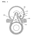
- a tensioner T which abuts against the outer surface of a belt is installed and adjusts the belt tension as shown in FIG. 3.
- the tensioner T of the prior art includes a support protrusion 301 projected from a motor housing, a first support shaft 303 extended through the support protrusion 301, a tensioner pulley 305 spaced from the support protrusion 301 at a predetermined distance, a second support protrusion 307 extended through the tensioner pulley 305, a swing arm 309 connecting the first support shaft 303 to the second support shaft 307 and a torsion spring 311 pushing against the swing arm 309 in one direction.
- the conventional tensioner T of this construction adjusts the tension of a belt 302 with the torsion spring 311, which applies spring force to the swing arm 309 to push against the belt 302 from outside to inside.
- a belt-type transmission including a rotatable drive shaft; a drive pulley coupled with the drive shaft; a rotatable driven shaft spaced from the drive shaft at a predetermined distance; a driven pulley coupled with the driven shaft; a belt connecting the drive shaft to the driven shaft; and a tensioner arranged inside and in contact with the belt.
- an electric power steering apparatus of an automobile including a pinion shaft connected to a steering wheel of the vehicle, and having a pinion gear formed on one end; a rack bar connected to both wheels of the vehicle, and having a rack gear formed in one end part to mesh with the pinion gear and a ball screw formed in the other end part; a motor for generating steering power in proportion to steering torque generated by the steering wheel; a motor pulley coupled with a motor shaft of the motor; a ball nut meshing with the ball screw of the rack bar via a ball; a ball nut pulley provided on an outer periphery of the ball nut; a belt connecting the motor pulley to the ball nut pulley; and a tensioner arranged inside and in contact with the belt.
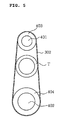
- a belt-type electric power transmission includes a rotatable drive shaft 401, a drive pulley 403 coupled with the drive shaft 401, a rotatable driven shaft 402 spaced from the drive shaft 401 to a predetermined distance, a driven pulley 404 coupled with the driven shaft 402, a belt 302 connecting the drive shaft 401 to the driven shaft 402 and a tensioner T abutting against the inner periphery of the belt 302.
- the drive shaft 401 is a cylindrical rotary shaft having a predetermined diameter, which delivers input rotational force to the driven shaft 402.
- An actuator such as a motor is connected to the input side 405 of the drive shaft 401 to rotate the drive shaft 401.
- the drive pulley 403 is configured to surround the outer periphery of the output side 407 of the rotary shaft 401, and the belt 302 moves in contact with the outer periphery of the drive pulley 403 to transmit rotational force from the drive shaft 401 to the driven shaft 402.
- the drive pulley 403 may be provided integral to the drive shaft 401, and protrusions may be formed on the outer periphery of the drive pulley 403 and the inner periphery of the belt 302 so that the belt 302 can have secure contact with the drive pulley 403.
- the driven shaft 402 functions to output rotational force delivered from the drive shaft 401.
- the driven shaft 402 is spaced from the drive shaft 401 at a predetermined distance to receive rotational force from the drive shaft 401.
- the driven pulley 404 is configured to surround the outer periphery of the driven shaft 402, and serves to deliver rotational force from the belt 302 to the driven shaft 402 as the belt 302 connected to the drive shaft 401 moves in contact with the outer periphery of the driven pulley 404.
- the belt 302 connects the drive shaft 401 to the driven shaft 402 to deliver rotational force from the drive shaft 401 to the driven shaft 402.
- the belt 302 may be provided by one or more, and made of various materials such as metal and plastic.
- the belt 302 may also be provided on the inner periphery with protrusions that mesh with protrusions of the drive shaft 401 and/or the driven shaft 402.
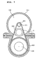
- the tensioner T has a cylindrical configuration, in contact with the inner periphery of the belt 302.
- the tensioner T may also be made hollow to reduce its weight.
- the tensioner T has a diameter larger than the width of the belt 302 without making inside-contact with the tensioner T (herein the term "inside-contact” means that the tensioner T is arranged inside and in contact with the belt 302), such that the tensioner T installed inside the belt 302 can push against the inner periphery of the belt 302 to make the belt 302 tight.
- the tensioner T can maintain a fixed position at all times owing to rotational force from both sides of the belt 302 that move in opposite direction.
- the tensioner T of this invention does not need additional support structure unlike conventional tensioners which are configured to contact the outside surface of the belt. Therefore, the invention can advantageously reduce the number of parts and simplify the manufacturing process, thereby saving manufacturing cost.
- the tensioner T may also be made of elastic material such as plastic in order to cope with the loosening of the belt owing to the abrasion of the inner periphery of the belt 302 or the outer periphery of the tensioner T. Then, even though the belt 302 loosens owing to abrasion, the elastic force of the tensioner T originating from its elasticity pushes the belt 302 outward so that the belt 302 can maintain its tension.
- an electric power steering apparatus includes a steering wheel 101, a pinion shaft 104 connected to the steering wheel 101, having a pinion gear 111 formed at the bottom thereof, a rack bar 109 connected to both wheels 108 and having a rack gear 112, which is formed at one part thereof and meshed with the pinion gear 111, a motor 130 for generating steering power in proportion to steering torque generated by the steering wheel 101, a motor pulley 601 coupled with the motor shaft 221, a ball nut 205 meshed with a ball screw 203 of the back bar 109 via balls 201, a ball nut pulley 602 arranged on the outer periphery of the ball nut 205, a belt 302 connecting a motor pulley 601 to a ball nut pulley 602 and a tensioner T contacting the inner periphery of the belt 302.
- the pinion shaft 104 is connected to the steering wheel 101 via a steering shaft 102, and the pinion gear 111 is formed at the bottom of the pinion shaft 104.
- the rack bar 109 is received in a rack housing, and connected at both ends to wheels 108 via tie rods 106 and knuckle arms 107.
- the rack gear 112 is formed on one part of the rack bar 109, and is meshed with the pinion gear 111. Also, seals for preventing the leakage of lubricant are provided at predetermined portions of the rack bar 109 inside from the both ends.
- the rack bar 109 receives, at one side, power from the motor shaft 221 via the belt 302.
- a spiral groove is extended to a predetermined length, forming the ball screw 203.
- the ball nut 205 meshes with the ball screw 203 via the balls 201, surrounding the outer periphery of the rack bar 109.
- the ball nut pulley 602 is arranged on the outer periphery of the ball nut 205, connecting the belt 302 to the ball nut 205.
- the ball nut pulley 602 may also be made integral with the ball nut 205.
- protrusions may be formed on the outer periphery of the ball nut pulley 602.
- the motor 130 includes a motor housing 611, a cover 613 that closes an opened end of the motor housing 611, a cylindrical stator 615 received in the motor housing 611, a rotor 617 arranged inside the stator 615 and the motor shaft 221 which is coupled integrally with the rotor 617.
- the motor shaft 221 is arranged to be parallel with the rack bar 109, with a left end 621 rotatably supported by a first bearing 623 installed in the motor housing 611 and a middle part rotatably supported by a second bearing 627 installed in the cover 613.
- the cover 613 is also coupled with the motor housing 611 via bolts 629.
- the motor pulley 601 is arranged on a right end 628 of the motor shaft 221 and the belt 302 is connected to the motor pulley 601 so that steering power generated by the motor 130 can be transmitted to the rack bar 109.
- the motor pulley 601 may be made integral with the motor shaft 221. Furthermore, protrusions may be formed on the outer periphery of the motor pulley 601.
- the belt 302 connects the motor pulley 601 to the ball nut pulley 602 to transmit steering power from the motor 130 to the rack bar 109. If necessary, protrusions may be formed on the inner periphery of the belt 302 to mesh with protrusions formed on the outer periphery of the motor pulley 601 or the ball nut pulley 602 so that the belt 302 can be driven in tight contact with the motor pulley 601 or the ball nut pulley 602.
- the tensioner T contacts the inner periphery of the belt 302 as in the first embodiment in order to push the belt 302 outward so that the belt 302 can maintain its tension.
- the tensioner is provided inside and in contact with the belt without additional support structure in order to adjust belt tension, this can advantageously reduce the number of parts and simplify manufacturing process, thereby saving manufacturing cost.
Landscapes
- Engineering & Computer Science (AREA)
- Chemical & Material Sciences (AREA)
- Combustion & Propulsion (AREA)
- Transportation (AREA)
- Mechanical Engineering (AREA)
- Power Steering Mechanism (AREA)
- Devices For Conveying Motion By Means Of Endless Flexible Members (AREA)
Applications Claiming Priority (1)
| Application Number | Priority Date | Filing Date | Title |
|---|---|---|---|
| KR1020050098474A KR20070042632A (ko) | 2005-10-19 | 2005-10-19 | 벨트식 전동장치 및 이를 구비한 자동차의 전기식 동력보조 조향장치 |
Publications (2)
| Publication Number | Publication Date |
|---|---|
| EP1777140A1 true EP1777140A1 (de) | 2007-04-25 |
| EP1777140B1 EP1777140B1 (de) | 2010-01-27 |
Family
ID=36283681
Family Applications (1)
| Application Number | Title | Priority Date | Filing Date |
|---|---|---|---|
| EP05257816A Expired - Lifetime EP1777140B1 (de) | 2005-10-19 | 2005-12-19 | Riemenspanner für eine elektrische Servolenkung mit Riemenantrieb |
Country Status (6)
| Country | Link |
|---|---|
| US (1) | US20070095600A1 (de) |
| EP (1) | EP1777140B1 (de) |
| JP (1) | JP2007112411A (de) |
| KR (1) | KR20070042632A (de) |
| CN (1) | CN100458222C (de) |
| DE (1) | DE602005019171D1 (de) |
Cited By (3)
| Publication number | Priority date | Publication date | Assignee | Title |
|---|---|---|---|---|
| DE102008001961A1 (de) * | 2008-05-26 | 2009-12-17 | Zf Lenksysteme Gmbh | Aktuator für ein Lenksystem |
| EP2535617A1 (de) * | 2011-06-15 | 2012-12-19 | Schaeffler Technologies AG & Co. KG | Aktuator zur Verstellung zweier relativ zueiander bewegbarer Bauteile |
| DE102016103197A1 (de) | 2016-02-24 | 2017-08-24 | Robert Bosch Automotive Steering Gmbh | Riemengetriebe und lenksystem |
Families Citing this family (13)
| Publication number | Priority date | Publication date | Assignee | Title |
|---|---|---|---|---|
| KR100625072B1 (ko) * | 2002-01-29 | 2006-09-19 | 가부시키가이샤 제이텍트 | 전동 파워스티어링 장치 |
| EP1886899A1 (de) * | 2006-08-10 | 2008-02-13 | Mando Corporation | Elektrische Servolenkung mit einem Mechanismus zur Einstellung der Spannung eines Riemens |
| DE102007004521A1 (de) * | 2007-01-24 | 2008-07-31 | Thyssenkrupp Presta Steertec Gmbh | Elektrische Servolenkung mit Riemenantrieb |
| DE102007004520A1 (de) * | 2007-01-24 | 2008-07-31 | Thyssenkrupp Presta Steertec Gmbh | Elektrische Servolenkung mit Riemenantrieb und berührungsloser Riemenspannung |
| DE102010003105A1 (de) * | 2010-03-22 | 2011-09-22 | Zf Lenksysteme Gmbh | Servolenkung |
| KR101452557B1 (ko) * | 2011-08-16 | 2014-10-21 | 주식회사 만도 | 전동식 동력 보조 조향장치 |
| DE102016113803A1 (de) * | 2015-07-28 | 2017-02-02 | Steering Solutions Ip Holding Corporation | Riemenscheibenbaugruppe mit leerlaufrolle, kraftunterstützungssystem mit riemenscheibenbaugruppe und verfahren |
| JP6657743B2 (ja) * | 2015-10-06 | 2020-03-04 | 株式会社ジェイテクト | ステアリング装置 |
| KR102312317B1 (ko) * | 2015-10-29 | 2021-10-14 | 주식회사 만도 | 전동식 동력 보조 조향장치 |
| US11247717B2 (en) * | 2018-05-11 | 2022-02-15 | Ford Global Technologies, Llc | Electric power assist steering assembly |
| WO2019220603A1 (ja) * | 2018-05-17 | 2019-11-21 | 株式会社ショーワ | 電動パワーステアリング装置 |
| DE102019115542A1 (de) * | 2018-06-08 | 2019-12-12 | Steering Solutions Ip Holding Corporation | Wartungsfähiger aggregat-riemenantrieb |
| KR20220141647A (ko) * | 2021-04-13 | 2022-10-20 | 주식회사 만도 | 자동차의 조향장치 |
Citations (5)
| Publication number | Priority date | Publication date | Assignee | Title |
|---|---|---|---|---|
| US3026737A (en) * | 1960-07-22 | 1962-03-27 | Pic Design Corp | Belt transmission system |
| US20030104889A1 (en) * | 2001-11-30 | 2003-06-05 | Redmond John D. | Idler sprocket |
| JP2003220958A (ja) | 2002-01-29 | 2003-08-05 | Koyo Seiko Co Ltd | 電動パワーステアリング装置 |
| JP2003291830A (ja) * | 2002-04-03 | 2003-10-15 | Honda Motor Co Ltd | 電動パワーステアリング装置 |
| EP1553006A1 (de) | 2002-08-22 | 2005-07-13 | Nsk Ltd., | Elektrische servolenkvorrichtung |
Family Cites Families (4)
| Publication number | Priority date | Publication date | Assignee | Title |
|---|---|---|---|---|
| US3574287A (en) * | 1969-09-19 | 1971-04-13 | Gen Motors Corp | Belt tension-adjusting device |
| US6126562A (en) * | 1995-09-14 | 2000-10-03 | Brangenfeldt; Torbjoern | Tensioning device for drive belts |
| JP4147836B2 (ja) * | 2002-06-21 | 2008-09-10 | 株式会社ジェイテクト | 車両用操舵装置 |
| US6960145B2 (en) * | 2002-08-30 | 2005-11-01 | Trw, Inc. | Belt tensioner for electric power steering unit |
-
2005
- 2005-10-19 KR KR1020050098474A patent/KR20070042632A/ko not_active Ceased
- 2005-12-19 EP EP05257816A patent/EP1777140B1/de not_active Expired - Lifetime
- 2005-12-19 DE DE602005019171T patent/DE602005019171D1/de not_active Expired - Lifetime
- 2005-12-19 US US11/311,722 patent/US20070095600A1/en not_active Abandoned
- 2005-12-19 JP JP2005365345A patent/JP2007112411A/ja active Pending
-
2006
- 2006-04-14 CN CNB2006100754502A patent/CN100458222C/zh not_active Expired - Fee Related
Patent Citations (5)
| Publication number | Priority date | Publication date | Assignee | Title |
|---|---|---|---|---|
| US3026737A (en) * | 1960-07-22 | 1962-03-27 | Pic Design Corp | Belt transmission system |
| US20030104889A1 (en) * | 2001-11-30 | 2003-06-05 | Redmond John D. | Idler sprocket |
| JP2003220958A (ja) | 2002-01-29 | 2003-08-05 | Koyo Seiko Co Ltd | 電動パワーステアリング装置 |
| JP2003291830A (ja) * | 2002-04-03 | 2003-10-15 | Honda Motor Co Ltd | 電動パワーステアリング装置 |
| EP1553006A1 (de) | 2002-08-22 | 2005-07-13 | Nsk Ltd., | Elektrische servolenkvorrichtung |
Non-Patent Citations (1)
| Title |
|---|
| PATENT ABSTRACTS OF JAPAN vol. 2003, no. 12 5 December 2003 (2003-12-05) * |
Cited By (3)
| Publication number | Priority date | Publication date | Assignee | Title |
|---|---|---|---|---|
| DE102008001961A1 (de) * | 2008-05-26 | 2009-12-17 | Zf Lenksysteme Gmbh | Aktuator für ein Lenksystem |
| EP2535617A1 (de) * | 2011-06-15 | 2012-12-19 | Schaeffler Technologies AG & Co. KG | Aktuator zur Verstellung zweier relativ zueiander bewegbarer Bauteile |
| DE102016103197A1 (de) | 2016-02-24 | 2017-08-24 | Robert Bosch Automotive Steering Gmbh | Riemengetriebe und lenksystem |
Also Published As
| Publication number | Publication date |
|---|---|
| US20070095600A1 (en) | 2007-05-03 |
| EP1777140B1 (de) | 2010-01-27 |
| JP2007112411A (ja) | 2007-05-10 |
| CN1952442A (zh) | 2007-04-25 |
| DE602005019171D1 (de) | 2010-03-18 |
| KR20070042632A (ko) | 2007-04-24 |
| CN100458222C (zh) | 2009-02-04 |
Similar Documents
| Publication | Publication Date | Title |
|---|---|---|
| US7278334B2 (en) | Electric power steering apparatus | |
| US7575090B2 (en) | Electric power steering device | |
| US6761244B2 (en) | Electric power steering apparatus | |
| EP1777140B1 (de) | Riemenspanner für eine elektrische Servolenkung mit Riemenantrieb | |
| KR100651141B1 (ko) | 자동차의 전기식 동력 보조 조향 장치 | |
| KR101454505B1 (ko) | 랙구동형 동력 보조 조향장치 | |
| JP2000043739A (ja) | 電動式舵取装置 | |
| EP1783031B1 (de) | Elektrische Fahrzeugservolenkung mit Riemengetriebe | |
| EP1764285A1 (de) | Elektrische Servolenkeinrichtung für ein Kraftfahrzeug | |
| CN109963769A (zh) | 转向系统 | |
| KR20110096816A (ko) | 전동식 동력 보조 조향장치의 감속기 및 이를 구비한 전동식 동력 보조 조향장치 | |
| JP2001322554A (ja) | 電動式舵取装置 | |
| JP2002187561A (ja) | 電動パワーステアリング装置 | |
| EP1900969B1 (de) | Untersetzungsgetriebe-Mechanismus und elektrische Servolenkung | |
| JP2004345444A (ja) | 電動パワーステアリング装置 | |
| JP2007186021A (ja) | 電動パワーステアリング装置 | |
| JP3782748B2 (ja) | 車両のステアリング装置 | |
| KR101121839B1 (ko) | 전동식 동력 보조 조향장치의 감속기 및 이를 이용한 전동식 동력 보조 조향장치 | |
| JP3950695B2 (ja) | 電動パワーステアリング装置 | |
| KR101424849B1 (ko) | 전동식 동력 보조 조향장치의 감속기 및 이를 구비한 전동식 동력 보조 조향장치 | |
| JP2005212654A (ja) | 電動パワーステアリング装置 | |
| JP2007050752A (ja) | 電動パワーステアリング装置 | |
| JP7461134B2 (ja) | 減速機の軸支持構造及びステアリング装置 | |
| JP2010023563A (ja) | 車両用操舵装置 | |
| JP2006182144A (ja) | 電動パワーステアリング装置用アングルセンサ |
Legal Events
| Date | Code | Title | Description |
|---|---|---|---|
| PUAI | Public reference made under article 153(3) epc to a published international application that has entered the european phase |
Free format text: ORIGINAL CODE: 0009012 |
|
| AK | Designated contracting states |
Kind code of ref document: A1 Designated state(s): AT BE BG CH CY CZ DE DK EE ES FI FR GB GR HU IE IS IT LI LT LU LV MC NL PL PT RO SE SI SK TR |
|
| AX | Request for extension of the european patent |
Extension state: AL BA HR MK YU |
|
| 17P | Request for examination filed |
Effective date: 20070829 |
|
| 17Q | First examination report despatched |
Effective date: 20070928 |
|
| AKX | Designation fees paid |
Designated state(s): DE FR GB IT |
|
| GRAP | Despatch of communication of intention to grant a patent |
Free format text: ORIGINAL CODE: EPIDOSNIGR1 |
|
| GRAS | Grant fee paid |
Free format text: ORIGINAL CODE: EPIDOSNIGR3 |
|
| GRAA | (expected) grant |
Free format text: ORIGINAL CODE: 0009210 |
|
| AK | Designated contracting states |
Kind code of ref document: B1 Designated state(s): DE FR GB IT |
|
| REG | Reference to a national code |
Ref country code: GB Ref legal event code: FG4D |
|
| REF | Corresponds to: |
Ref document number: 602005019171 Country of ref document: DE Date of ref document: 20100318 Kind code of ref document: P |
|
| PLBE | No opposition filed within time limit |
Free format text: ORIGINAL CODE: 0009261 |
|
| STAA | Information on the status of an ep patent application or granted ep patent |
Free format text: STATUS: NO OPPOSITION FILED WITHIN TIME LIMIT |
|
| 26N | No opposition filed |
Effective date: 20101028 |
|
| GBPC | Gb: european patent ceased through non-payment of renewal fee |
Effective date: 20101219 |
|
| REG | Reference to a national code |
Ref country code: FR Ref legal event code: ST Effective date: 20110831 |
|
| PG25 | Lapsed in a contracting state [announced via postgrant information from national office to epo] |
Ref country code: FR Free format text: LAPSE BECAUSE OF NON-PAYMENT OF DUE FEES Effective date: 20110103 |
|
| PG25 | Lapsed in a contracting state [announced via postgrant information from national office to epo] |
Ref country code: GB Free format text: LAPSE BECAUSE OF NON-PAYMENT OF DUE FEES Effective date: 20101219 |
|
| PG25 | Lapsed in a contracting state [announced via postgrant information from national office to epo] |
Ref country code: IT Free format text: LAPSE BECAUSE OF NON-PAYMENT OF DUE FEES Effective date: 20101219 |
|
| REG | Reference to a national code |
Ref country code: DE Ref legal event code: R081 Ref document number: 602005019171 Country of ref document: DE Owner name: HL MANDO CORPORATION, PYEONGTAEK-SI, KR Free format text: FORMER OWNER: MANDO CORP., PYUNGTAEK, KYONGGI, KR |
|
| PGFP | Annual fee paid to national office [announced via postgrant information from national office to epo] |
Ref country code: DE Payment date: 20230822 Year of fee payment: 19 |
|
| REG | Reference to a national code |
Ref country code: DE Ref legal event code: R119 Ref document number: 602005019171 Country of ref document: DE |
|
| PG25 | Lapsed in a contracting state [announced via postgrant information from national office to epo] |
Ref country code: DE Free format text: LAPSE BECAUSE OF NON-PAYMENT OF DUE FEES Effective date: 20250701 |