EP1777361A2 - Serrure, notamment serrure encastrée - Google Patents
Serrure, notamment serrure encastrée Download PDFInfo
- Publication number
- EP1777361A2 EP1777361A2 EP06022129A EP06022129A EP1777361A2 EP 1777361 A2 EP1777361 A2 EP 1777361A2 EP 06022129 A EP06022129 A EP 06022129A EP 06022129 A EP06022129 A EP 06022129A EP 1777361 A2 EP1777361 A2 EP 1777361A2
- Authority
- EP
- European Patent Office
- Prior art keywords
- lock
- access control
- electronics
- reading
- control electronics
- Prior art date
- Legal status (The legal status is an assumption and is not a legal conclusion. Google has not performed a legal analysis and makes no representation as to the accuracy of the status listed.)
- Withdrawn
Links
- 230000008878 coupling Effects 0.000 claims abstract description 9
- 238000010168 coupling process Methods 0.000 claims abstract description 9
- 238000005859 coupling reaction Methods 0.000 claims abstract description 9
- 238000013475 authorization Methods 0.000 description 2
- 230000010354 integration Effects 0.000 description 2
- 230000000903 blocking effect Effects 0.000 description 1
- 238000010276 construction Methods 0.000 description 1
- 238000009434 installation Methods 0.000 description 1
- 239000002184 metal Substances 0.000 description 1
- 230000003287 optical effect Effects 0.000 description 1
- 238000009420 retrofitting Methods 0.000 description 1
- 239000002023 wood Substances 0.000 description 1
Images

Classifications
-
- E—FIXED CONSTRUCTIONS
- E05—LOCKS; KEYS; WINDOW OR DOOR FITTINGS; SAFES
- E05B—LOCKS; ACCESSORIES THEREFOR; HANDCUFFS
- E05B47/00—Operating or controlling locks or other fastening devices by electric or magnetic means
- E05B47/06—Controlling mechanically-operated bolts by electro-magnetically-operated detents
- E05B47/0676—Controlling mechanically-operated bolts by electro-magnetically-operated detents by disconnecting the handle
-
- G—PHYSICS
- G07—CHECKING-DEVICES
- G07C—TIME OR ATTENDANCE REGISTERS; REGISTERING OR INDICATING THE WORKING OF MACHINES; GENERATING RANDOM NUMBERS; VOTING OR LOTTERY APPARATUS; ARRANGEMENTS, SYSTEMS OR APPARATUS FOR CHECKING NOT PROVIDED FOR ELSEWHERE
- G07C9/00—Individual registration on entry or exit
- G07C9/00174—Electronically operated locks; Circuits therefor; Nonmechanical keys therefor, e.g. passive or active electrical keys or other data carriers without mechanical keys
- G07C9/00309—Electronically operated locks; Circuits therefor; Nonmechanical keys therefor, e.g. passive or active electrical keys or other data carriers without mechanical keys operated with bidirectional data transmission between data carrier and locks
-
- E—FIXED CONSTRUCTIONS
- E05—LOCKS; KEYS; WINDOW OR DOOR FITTINGS; SAFES
- E05B—LOCKS; ACCESSORIES THEREFOR; HANDCUFFS
- E05B47/00—Operating or controlling locks or other fastening devices by electric or magnetic means
- E05B2047/0094—Mechanical aspects of remotely controlled locks
-
- E—FIXED CONSTRUCTIONS
- E05—LOCKS; KEYS; WINDOW OR DOOR FITTINGS; SAFES
- E05B—LOCKS; ACCESSORIES THEREFOR; HANDCUFFS
- E05B47/00—Operating or controlling locks or other fastening devices by electric or magnetic means
- E05B47/0001—Operating or controlling locks or other fastening devices by electric or magnetic means with electric actuators; Constructional features thereof
- E05B47/0012—Operating or controlling locks or other fastening devices by electric or magnetic means with electric actuators; Constructional features thereof with rotary electromotors
-
- G—PHYSICS
- G07—CHECKING-DEVICES
- G07C—TIME OR ATTENDANCE REGISTERS; REGISTERING OR INDICATING THE WORKING OF MACHINES; GENERATING RANDOM NUMBERS; VOTING OR LOTTERY APPARATUS; ARRANGEMENTS, SYSTEMS OR APPARATUS FOR CHECKING NOT PROVIDED FOR ELSEWHERE
- G07C9/00—Individual registration on entry or exit
- G07C9/00174—Electronically operated locks; Circuits therefor; Nonmechanical keys therefor, e.g. passive or active electrical keys or other data carriers without mechanical keys
- G07C2009/00753—Electronically operated locks; Circuits therefor; Nonmechanical keys therefor, e.g. passive or active electrical keys or other data carriers without mechanical keys operated by active electrical keys
- G07C2009/00769—Electronically operated locks; Circuits therefor; Nonmechanical keys therefor, e.g. passive or active electrical keys or other data carriers without mechanical keys operated by active electrical keys with data transmission performed by wireless means
- G07C2009/00777—Electronically operated locks; Circuits therefor; Nonmechanical keys therefor, e.g. passive or active electrical keys or other data carriers without mechanical keys operated by active electrical keys with data transmission performed by wireless means by induction
Definitions
- the invention relates to a lock, in particular Einstemmtsch, with a case, in particular a Springfalle, which is actuated via a nut, in particular a follower nut, wherein the nut is formed as a split nut and one, in particular the inside of the door, nut half with the case always in Intervention is and the other, in particular the outside of the door nut half can be coupled via a coupling with the case and in which optionally a lock cylinder is used.
- a lock of the type mentioned is from the AT 004 296 U1 known.
- the locking lug of the lock cylinder is kinematically connected to the nut.
- the object of the invention is to provide a lock of the type mentioned above, on the one hand avoids the above-mentioned disadvantages and on the other hand so has a simple structure and offers the current standards, especially for example in hotel operation, corresponding high security.
- the lock according to the invention is characterized in that the coupling is controllable via an access control electronics integrated in the lock housing and the access control electronics are connected to a reading antenna.
- the invention makes it possible for the first time to offer a lock, in particular a puncture lock, in mechatronic design for universal installation on the market, which can also be manufactured extremely economically in production.
- the advantage of this lock according to the invention is the fact that it can be used universally in many, preferably in all standardized, fitting types. For example, especially in the hotel and hospitality industry, a high standard in terms of security is required of the corresponding locks.
- the lock according to the invention fulfills all these requirements.
- the integration of the access control electronics in the lock housing an economical and efficient production is ensured.
- the access control electronics on at least one processor and optionally at least one read and / or write electronics for an electronic key.
- the integration of the access control electronics in the lock housing, the door leaf outer side of the castle is enormous reduced. Bulky, for the optical impression chunky exterior parts of the castle are avoided.
- the processor of the access control electronics has the task to compare the access authorizations with the detected key code.
- the read and / or write electronics could also have another processor which is used to read the key code.
- the reading antenna is connected via the reading and / or writing electronics with the access control electronics.
- the constructive configurations of the arrangement of the read and / or write electronics have no limits.
- One embodiment is to design the read and / or write electronics with the access control electronics as a unit or as a module in the lock housing.
- the reading and / or write electronics with the reading antenna is designed as a module.
- the advantage of this design is that a retrofit kit for locks can be offered.
- the read and / or write electronics with the reading antenna and a battery is designed as a module.
- an economical solution of the constructive placement of the power supply is achieved.
- the module is designed as a cylinder module, preferably with an outer diameter of 35 - 48 mm.
- a cylinder module preferably with an outer diameter of 35 - 48 mm.
- the access control electronics is connected to a, preferably usable in the lock housing, lock cylinder.
- Locking cylinders increase safety. All common lock cylinders can also be used in the lock according to the invention.
- the lock cylinder may be a prior art conventional lock cylinder with scanning pins. This conventional lock cylinder could then have an "emergency lock" function. Especially important is the reading electronics for identifying the key code, wherein the key code from an antenna, a reading field on the outside of the door, is detected.
- the write electronics offer the advantage that the battery status and / or the blocking time is stored on the electronic key.
- the lock cylinder is an electronic lock cylinder. With such a type of lock cylinder, it is possible to realize a fully digitized locking system.
- the reading and / or writing electronics and optionally a reading antenna for an electronic key in the electronic lock cylinder is integrated.
- this embodiment is of particular advantage.
- At least one limit switch for the case and / or at least one limit switch for the clutch can be controlled via the access control electronics.
- the access control electronics on an operable via the locking lug of the lock cylinder switch.
- This switch has the function "Do Not Disturb” and replaces a mechanical latch. If this switch is actuated by the locking lug in the locking direction, this switch reports this locking request of the access control electronics and thus allows no coupling of the two halves nut for ordinary opening attempts. Only over a key with a special coding can the lock be operated in case of emergency.
- the clutch via a, preferably operated with a motor, spindle drive on or disengaged.
- spindle drives have the advantage that high forces can be mustered with the smallest construction.
- a lock in the example shown, a mortise lock 1 is used to secure a door, possibly inter alia.
- the unsecured, or publicly accessible side of a door is referred to as the outside and the secured side of the door as the inside.
- the lock has no bar.
- the required space for the bolt space is used for the electronics. You could also call this lock as a mechatronic Einstemmsch 1.
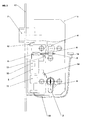
- the mechanical basic components of the Einstemmtsches 1 in the lock housing are a case 7, which is designed as a spring latch and a nut 4, which is in kinematical connection with the case, a mechanical clutch 8, which has a spindle drive 9, driven by a motor 5 and optionally a lock cylinder. 2
- the nut 4 preferably designed as a follower, is divided, wherein the dividing plane for the two nut halves is radial.
- the two nut halves, formed quasi disc-shaped, are each stored separately in the lock housing and can be moved independently of each other in the uncoupled state.
- the lock has a split nut 4, ie from the outside, the outer half of the nut can rotate freely without the trap 7 to operate. From the inside, the inner nut half and thus also the latch 7 can always be actuated become. This is of utmost importance in terms of the so-called panic function.
- the outer half of the nut is motor-driven via a spindle drive 9 on or disengaged.
- the outer half of the nut can be engaged after checking the electronic key and thus allow the opening of a door.
- the Einstemmtsch 1 in place of the usual bolt on a spring trap.
- the Springfalle is pressed after closing the door in the strike plate by a spring and thus replaces the otherwise required for security latch.
- the spring latch is retracted by turning one or both nut halves back to the starting position (see Fig.2) and the spring which is required for the feed is biased. In this position according to FIG. 2, the latch 7 remains as long as the door is open. After closing a type of trigger is actuated, which triggers the lock and thus the case jumps 7 in the strike plate - the door is thus locked.
- the electrical or electronic main component is above all an access control electronics 3, which has at least one processor 10.
- a read and / or write electronics 11 is further provided in the lock housing, which is connected to the access control electronics 3.
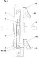
- the power is supplied via a cable 15 with a plug 16 to a, a battery having, reading antenna 18 (Fig. 3) from the outside.
- the reader antenna 18 is the reading field on the outside of the door. Even in the closed state of the door thus a battery change is ensured.
- the reading electronics serve to identify the key code, the key code being detected by an antenna, a reading field on the outside of the door.
- the writing electronics can on the electronic key the battery status and / or the lock time is stored. Both data can be read out from the electronic key on a central computer.
- At least the reading and / or write electronics 11 could be provided in the electronic lock cylinder 2.
- the access control electronics 3 controls the motor 5 for the spindle drive 9 of the clutch eighth
- an operable by the case 7 limit switch 12 is provided which interrupts the power supply after the identification of the access authorization.
- a further limit switch 13 is provided in the region of the clutch 8, via which an emergency opening can be detected via the lock cylinder 2.
- the switch 14 has the function "Do not disturb” and replaces a mechanical latch.
- This switch 14 reports this Zusperrin the access control electronics 3, and thus allows no coupling of the two nut halves for ordinary opening attempts.
- the processor 10 controls the motor-driven clutch 8 only when reading a specially coded key. All other keys can not exercise a disabling function. This feature is especially important when using electronic keys. With this switch 14 access to a room is granted only authorized parent persons and guarantees a privacy, for example, in a hotel room, bathroom, dressing room, toilet or the like.
- FIG. 3 the mortise lock 1, which is installed in a door, is shown, the arrangements of the components being indicated sketchily in accordance with the various design variants.
Landscapes
- Engineering & Computer Science (AREA)
- Computer Networks & Wireless Communication (AREA)
- Physics & Mathematics (AREA)
- General Physics & Mathematics (AREA)
- Lock And Its Accessories (AREA)
Applications Claiming Priority (2)
| Application Number | Priority Date | Filing Date | Title |
|---|---|---|---|
| AT0071905U AT8701U1 (de) | 2005-10-24 | 2005-10-24 | Schloss |
| AT0053806U AT9525U1 (de) | 2005-10-24 | 2006-07-10 | Schloss |
Publications (2)
| Publication Number | Publication Date |
|---|---|
| EP1777361A2 true EP1777361A2 (fr) | 2007-04-25 |
| EP1777361A3 EP1777361A3 (fr) | 2008-10-01 |
Family
ID=37806860
Family Applications (1)
| Application Number | Title | Priority Date | Filing Date |
|---|---|---|---|
| EP06022129A Withdrawn EP1777361A3 (fr) | 2005-10-24 | 2006-10-23 | Serrure, notamment serrure encastrée |
Country Status (2)
| Country | Link |
|---|---|
| EP (1) | EP1777361A3 (fr) |
| AT (1) | AT9525U1 (fr) |
Citations (7)
| Publication number | Priority date | Publication date | Assignee | Title |
|---|---|---|---|---|
| DE495411C (de) | 1930-04-07 | Ernst Goettlicher | Einstemmschloss mit als Riegel dienender Falle | |
| FR2628471A1 (fr) | 1988-03-09 | 1989-09-15 | Werke Gestion Securit | Ensemble electronique de fermeture |
| AT392510B (de) | 1988-06-01 | 1991-04-25 | Grundmann Gmbh Geb | Schloss mit mechanischer und elektronischer sperreinrichtung |
| AT4296U1 (de) | 2000-05-02 | 2001-05-25 | Kaba Gege Gmbh | Einstemmschloss mit falle |
| DE10028176A1 (de) | 2000-06-09 | 2001-12-13 | Michael Dorn | Selbstverriegelndes Schloß und mit diesem ausgestattetes Schließsystem |
| EP1174570A1 (fr) | 2000-07-21 | 2002-01-23 | Harrow Products Inc. | Serrure à mortaise avec embrayage interne |
| EP1431481A2 (fr) | 2002-12-20 | 2004-06-23 | GEZE GmbH | Serrure |
-
2006
- 2006-07-10 AT AT0053806U patent/AT9525U1/de not_active IP Right Cessation
- 2006-10-23 EP EP06022129A patent/EP1777361A3/fr not_active Withdrawn
Patent Citations (7)
| Publication number | Priority date | Publication date | Assignee | Title |
|---|---|---|---|---|
| DE495411C (de) | 1930-04-07 | Ernst Goettlicher | Einstemmschloss mit als Riegel dienender Falle | |
| FR2628471A1 (fr) | 1988-03-09 | 1989-09-15 | Werke Gestion Securit | Ensemble electronique de fermeture |
| AT392510B (de) | 1988-06-01 | 1991-04-25 | Grundmann Gmbh Geb | Schloss mit mechanischer und elektronischer sperreinrichtung |
| AT4296U1 (de) | 2000-05-02 | 2001-05-25 | Kaba Gege Gmbh | Einstemmschloss mit falle |
| DE10028176A1 (de) | 2000-06-09 | 2001-12-13 | Michael Dorn | Selbstverriegelndes Schloß und mit diesem ausgestattetes Schließsystem |
| EP1174570A1 (fr) | 2000-07-21 | 2002-01-23 | Harrow Products Inc. | Serrure à mortaise avec embrayage interne |
| EP1431481A2 (fr) | 2002-12-20 | 2004-06-23 | GEZE GmbH | Serrure |
Also Published As
| Publication number | Publication date |
|---|---|
| EP1777361A3 (fr) | 2008-10-01 |
| AT9525U1 (de) | 2007-11-15 |
Similar Documents
| Publication | Publication Date | Title |
|---|---|---|
| DE112007001299B4 (de) | Nockenschloss mit rückziehbarem Dorn | |
| EP1842989B1 (fr) | Serrure à mortaiser | |
| DE8915994U1 (de) | Kraftfahrzeugtürverschluß mit einem Zentralverriegelungsantrieb | |
| DE19930054C2 (de) | Elektromechanisches Schließsystem | |
| DE9114609U1 (de) | Türschloß | |
| DE19603200C2 (de) | Elektronisches Türschloß | |
| DE102013100304A1 (de) | Kupplungsvorrichtung | |
| EP2679751A2 (fr) | Dispositif de verrouillage et battant ou installation de battant équipé de celui-ci | |
| DE19906271C2 (de) | Schloßkasten für eine Tür | |
| EP1908899A2 (fr) | Système de verrouillage | |
| EP2862992B1 (fr) | Multi-serrure | |
| DE102018133069B4 (de) | Elektronisches Schloss mit einem Drucktaster für eine Türmontage | |
| AT9525U1 (de) | Schloss | |
| AT511829B1 (de) | Verriegelungseinrichtung sowie Rohrtresor mit einer Verriegelungseinrichtung | |
| EP0519905A1 (fr) | Serrure encastrée | |
| AT8701U1 (de) | Schloss | |
| EP1356177A1 (fr) | Dispositif de fermeture a commande electronique | |
| DE29923398U1 (de) | Schließsystem für Möbel | |
| EP2060708A2 (fr) | Ecran pour un verrou | |
| DE19516088C2 (de) | Schloß | |
| DE20102279U1 (de) | Elektronisch steuerbare Schließvorrichtung | |
| DE102017206927A1 (de) | Schließanlage | |
| AT512320B1 (de) | Rohrtresor mit einer Verriegelungseinrichtung | |
| DE19547255C1 (de) | Zusatzverriegelung | |
| DE102005017896B4 (de) | Sicherheitsschloss mit Codierung |
Legal Events
| Date | Code | Title | Description |
|---|---|---|---|
| PUAI | Public reference made under article 153(3) epc to a published international application that has entered the european phase |
Free format text: ORIGINAL CODE: 0009012 |
|
| AK | Designated contracting states |
Kind code of ref document: A2 Designated state(s): AT BE BG CH CY CZ DE DK EE ES FI FR GB GR HU IE IS IT LI LT LU LV MC NL PL PT RO SE SI SK TR |
|
| AX | Request for extension of the european patent |
Extension state: AL BA HR MK YU |
|
| PUAL | Search report despatched |
Free format text: ORIGINAL CODE: 0009013 |
|
| AK | Designated contracting states |
Kind code of ref document: A3 Designated state(s): AT BE BG CH CY CZ DE DK EE ES FI FR GB GR HU IE IS IT LI LT LU LV MC NL PL PT RO SE SI SK TR |
|
| AX | Request for extension of the european patent |
Extension state: AL BA HR MK RS |
|
| 17P | Request for examination filed |
Effective date: 20090331 |
|
| 17Q | First examination report despatched |
Effective date: 20090512 |
|
| AKX | Designation fees paid |
Designated state(s): AT BE BG CH CY CZ DE DK EE ES FI FR GB GR HU IE IS IT LI LT LU LV MC NL PL PT RO SE SI SK TR |
|
| AXX | Extension fees paid |
Extension state: RS Payment date: 20090401 Extension state: MK Payment date: 20090401 Extension state: HR Payment date: 20090331 Extension state: BA Payment date: 20090401 Extension state: AL Payment date: 20090401 |
|
| RAP1 | Party data changed (applicant data changed or rights of an application transferred) |
Owner name: MAKIVIC, MICHAEL |
|
| STAA | Information on the status of an ep patent application or granted ep patent |
Free format text: STATUS: THE APPLICATION IS DEEMED TO BE WITHDRAWN |
|
| 18D | Application deemed to be withdrawn |
Effective date: 20150505 |