EP2679751A2 - Dispositif de verrouillage et battant ou installation de battant équipé de celui-ci - Google Patents
Dispositif de verrouillage et battant ou installation de battant équipé de celui-ci Download PDFInfo
- Publication number
- EP2679751A2 EP2679751A2 EP20130002749 EP13002749A EP2679751A2 EP 2679751 A2 EP2679751 A2 EP 2679751A2 EP 20130002749 EP20130002749 EP 20130002749 EP 13002749 A EP13002749 A EP 13002749A EP 2679751 A2 EP2679751 A2 EP 2679751A2
- Authority
- EP
- European Patent Office
- Prior art keywords
- locking
- housing
- wing
- locking element
- handle
- Prior art date
- Legal status (The legal status is an assumption and is not a legal conclusion. Google has not performed a legal analysis and makes no representation as to the accuracy of the status listed.)
- Withdrawn
Links
Images


Classifications
-
- E—FIXED CONSTRUCTIONS
- E05—LOCKS; KEYS; WINDOW OR DOOR FITTINGS; SAFES
- E05C—BOLTS OR FASTENING DEVICES FOR WINGS, SPECIALLY FOR DOORS OR WINDOWS
- E05C1/00—Fastening devices with bolts moving rectilinearly
- E05C1/02—Fastening devices with bolts moving rectilinearly without latching action
- E05C1/06—Fastening devices with bolts moving rectilinearly without latching action with operating handle or equivalent member moving otherwise than rigidly with the bolt
-
- E—FIXED CONSTRUCTIONS
- E05—LOCKS; KEYS; WINDOW OR DOOR FITTINGS; SAFES
- E05B—LOCKS; ACCESSORIES THEREFOR; HANDCUFFS
- E05B1/00—Knobs or handles for wings; Knobs, handles, or press buttons for locks or latches on wings
- E05B1/0038—Sliding handles, e.g. push buttons
-
- E—FIXED CONSTRUCTIONS
- E05—LOCKS; KEYS; WINDOW OR DOOR FITTINGS; SAFES
- E05B—LOCKS; ACCESSORIES THEREFOR; HANDCUFFS
- E05B1/00—Knobs or handles for wings; Knobs, handles, or press buttons for locks or latches on wings
- E05B1/0038—Sliding handles, e.g. push buttons
- E05B1/0046—Sliding handles, e.g. push buttons sliding parallel to the plane of the wing
-
- E—FIXED CONSTRUCTIONS
- E05—LOCKS; KEYS; WINDOW OR DOOR FITTINGS; SAFES
- E05B—LOCKS; ACCESSORIES THEREFOR; HANDCUFFS
- E05B19/00—Keys; Accessories therefor
-
- E—FIXED CONSTRUCTIONS
- E05—LOCKS; KEYS; WINDOW OR DOOR FITTINGS; SAFES
- E05B—LOCKS; ACCESSORIES THEREFOR; HANDCUFFS
- E05B63/00—Locks or fastenings with special structural characteristics
- E05B63/0017—Locks with sliding bolt without provision for latching
-
- E—FIXED CONSTRUCTIONS
- E05—LOCKS; KEYS; WINDOW OR DOOR FITTINGS; SAFES
- E05B—LOCKS; ACCESSORIES THEREFOR; HANDCUFFS
- E05B63/00—Locks or fastenings with special structural characteristics
- E05B63/16—Locks or fastenings with special structural characteristics with the handles on opposite sides moving independently
-
- E—FIXED CONSTRUCTIONS
- E05—LOCKS; KEYS; WINDOW OR DOOR FITTINGS; SAFES
- E05B—LOCKS; ACCESSORIES THEREFOR; HANDCUFFS
- E05B65/00—Locks or fastenings for special use
- E05B65/08—Locks or fastenings for special use for sliding wings
- E05B65/087—Locks or fastenings for special use for sliding wings the bolts sliding parallel to the wings
- E05B65/0876—Locks or fastenings for special use for sliding wings the bolts sliding parallel to the wings cooperating with the slide guide, e.g. the rail
-
- E—FIXED CONSTRUCTIONS
- E05—LOCKS; KEYS; WINDOW OR DOOR FITTINGS; SAFES
- E05B—LOCKS; ACCESSORIES THEREFOR; HANDCUFFS
- E05B65/00—Locks or fastenings for special use
- E05B65/10—Locks or fastenings for special use for panic or emergency doors
- E05B65/1086—Locks with panic function, e.g. allowing opening from the inside without a ley even when locked from the outside
-
- E—FIXED CONSTRUCTIONS
- E05—LOCKS; KEYS; WINDOW OR DOOR FITTINGS; SAFES
- E05B—LOCKS; ACCESSORIES THEREFOR; HANDCUFFS
- E05B9/00—Lock casings or latch-mechanism casings ; Fastening locks or fasteners or parts thereof to the wing
- E05B9/02—Casings of latch-bolt or deadbolt locks
-
- E—FIXED CONSTRUCTIONS
- E05—LOCKS; KEYS; WINDOW OR DOOR FITTINGS; SAFES
- E05B—LOCKS; ACCESSORIES THEREFOR; HANDCUFFS
- E05B15/00—Other details of locks; Parts for engagement by bolts of fastening devices
- E05B15/10—Bolts of locks or night latches
-
- E—FIXED CONSTRUCTIONS
- E05—LOCKS; KEYS; WINDOW OR DOOR FITTINGS; SAFES
- E05B—LOCKS; ACCESSORIES THEREFOR; HANDCUFFS
- E05B47/00—Operating or controlling locks or other fastening devices by electric or magnetic means
- E05B2047/0094—Mechanical aspects of remotely controlled locks
-
- E—FIXED CONSTRUCTIONS
- E05—LOCKS; KEYS; WINDOW OR DOOR FITTINGS; SAFES
- E05B—LOCKS; ACCESSORIES THEREFOR; HANDCUFFS
- E05B47/00—Operating or controlling locks or other fastening devices by electric or magnetic means
- E05B47/06—Controlling mechanically-operated bolts by electro-magnetically-operated detents
- E05B47/0611—Cylinder locks with electromagnetic control
- E05B47/0638—Cylinder locks with electromagnetic control by disconnecting the rotor
-
- E—FIXED CONSTRUCTIONS
- E05—LOCKS; KEYS; WINDOW OR DOOR FITTINGS; SAFES
- E05B—LOCKS; ACCESSORIES THEREFOR; HANDCUFFS
- E05B47/00—Operating or controlling locks or other fastening devices by electric or magnetic means
- E05B47/06—Controlling mechanically-operated bolts by electro-magnetically-operated detents
- E05B47/0676—Controlling mechanically-operated bolts by electro-magnetically-operated detents by disconnecting the handle
-
- E—FIXED CONSTRUCTIONS
- E05—LOCKS; KEYS; WINDOW OR DOOR FITTINGS; SAFES
- E05B—LOCKS; ACCESSORIES THEREFOR; HANDCUFFS
- E05B65/00—Locks or fastenings for special use
- E05B65/0025—Locks or fastenings for special use for glass wings
-
- E—FIXED CONSTRUCTIONS
- E05—LOCKS; KEYS; WINDOW OR DOOR FITTINGS; SAFES
- E05B—LOCKS; ACCESSORIES THEREFOR; HANDCUFFS
- E05B65/00—Locks or fastenings for special use
- E05B65/0035—Locks or fastenings for special use for privacy rooms, e.g. bathrooms
-
- Y—GENERAL TAGGING OF NEW TECHNOLOGICAL DEVELOPMENTS; GENERAL TAGGING OF CROSS-SECTIONAL TECHNOLOGIES SPANNING OVER SEVERAL SECTIONS OF THE IPC; TECHNICAL SUBJECTS COVERED BY FORMER USPC CROSS-REFERENCE ART COLLECTIONS [XRACs] AND DIGESTS
- Y10—TECHNICAL SUBJECTS COVERED BY FORMER USPC
- Y10T—TECHNICAL SUBJECTS COVERED BY FORMER US CLASSIFICATION
- Y10T292/00—Closure fasteners
- Y10T292/08—Bolts
- Y10T292/0863—Sliding and rotary
-
- Y—GENERAL TAGGING OF NEW TECHNOLOGICAL DEVELOPMENTS; GENERAL TAGGING OF CROSS-SECTIONAL TECHNOLOGIES SPANNING OVER SEVERAL SECTIONS OF THE IPC; TECHNICAL SUBJECTS COVERED BY FORMER USPC CROSS-REFERENCE ART COLLECTIONS [XRACs] AND DIGESTS
- Y10—TECHNICAL SUBJECTS COVERED BY FORMER USPC
- Y10T—TECHNICAL SUBJECTS COVERED BY FORMER US CLASSIFICATION
- Y10T70/00—Locks
- Y10T70/70—Operating mechanism
- Y10T70/7441—Key
- Y10T70/7486—Single key
Definitions
- the invention relates to a locking device for wings and wing equipped therewith and equipped with such a wing wing system.
- Locking devices are known per se.
- One is a conventional door lock whose bolt prevents the relevant wing of a wing system, to be pivoted in the opening direction.
- a key operated profile cylinder or a knob or door handle may be provided, the operation of the latch between locking and unlocking or release position in which the wing is no longer hindered in its movement is moved.
- a locking bolt which engages in the locking position in a corresponding recess, which in turn is formed in a relative to the wing system fixed element, such as the ground. This also prevents the relevant wing from being moved.
- a sliding handle may be provided, by means of which the movement of the locking bolt is moved accordingly.
- the object of the invention is to overcome the disadvantages of the prior art.
- a locking device which has a housing.
- the housing is designed to be used fixed in a wing or to be attached to this stationary. Ie. the housing is securely held on or in the relevant wing.
- the locking device has a translationally in the housing and out of this movable locking element. When it is moved out, it is in the locking position and stands out of the housing.
- the locking device comprises at least a first actuating device, which in relation to the housing of includes externally accessible handle. This grip is operatively connected to the locking element such that upon movement of this grip along a predetermined path of travel, the locking element is moved into or out of the housing. Ie.
- the handle allows a person to move about the locking element in the direction of locking position or away from it and thus in unlocking or release position.
- the locking device also has a second actuating device, which is accommodated in the aforementioned housing.
- This actuating device comprises a rotatably operable transmission device. This can be rotated or rotated by means of a rotating part.
- the rotating part itself is analogous to the handle accessible with respect to the housing from the outside.
- the rotary member is designed and operatively connected to the locking element, that the locking element is moved out of the housing in the aforementioned rotation or rotation of the rotary member in a locking direction. Ie. the rotating part has the same effect on the locking element as the handle.
- this solution has the advantage that the grip piece can be actuated from the inside of the relevant wing. Ie. no key or the like is required here.
- the rotary part can be formed, for example, as a single-sided accessible profile cylinder, ie as a half-cylinder, whose keyway is accessible from the outside of the wing. This makes it possible to lock and unlock a wing by means of different actuators, but with one and the same locking element. This simplifies the structure of the wing, and the operability is improved or remains. In addition, the costs remain low.
- the locking device is further designed so that when moving the handle or the rotary member, the rotary member or the handle is moved. Ie. the movement of one part is transmitted corresponding to the other part.
- the rotary member is rotated in a direction which would also perform the rotary member when a person wanted to move the locking member in the locked position by means of the rotary member. This simplifies the construction of the locking device, since the handle and rotating part with respect to their movements do not have to be decoupled from each other.
- the locking device according to the invention may be further designed to lock the locking element at least in the locked position. This increases the security to the effect that the lock can not solve easily.
- the housing is advantageously designed according to the respectively to be locked position of the locking element corresponding to prevent the handle or the rotary member at a movement away from its locked position at least to a predetermined extent. This makes it possible to accomplish the locking over just the handle or the rotary member; additional funds are not required. In addition, if the aforementioned movement coupling between handle and rotating part, so both parts are locked at the same time. As a result, the user notices via the locking of the grip piece or of the rotary part that the locking element is locked.
- Each of the aforementioned locking devices may further comprise means, the locking element in the direction of locking position or to push away from it. Ie. the user is assisted in the respective movement of the locking element, which increases the ease of use.
- the first actuating device and / or the second actuating device can also be designed and operatively connected to the locking element such that the locking element moves when the grip part moves or the rotary part rotates in a direction corresponding to a direction of movement of the locking element from the locking position weg corresponds, is moved into the housing into it. Ie. by means of the handle or the rotary part, the locking element can also be moved back into the housing and thus away from the locking position; additional items are not required. This keeps the structure very simple.
- the rotary member may comprise a cam outer circumference, which is rotated at a rotation of the rotary member and in a predetermined portion of the rotational movement, the locking member entrains and thereby the locking element is moved translationally.
- This arrangement essentially corresponds to a conventional lock cylinder arrangement. Ie. It can be used known and inexpensive to produce parts.
- the rotary member preferably has a single-sided or double-sided accessible profile cylinder. This type of rotary member is fixedly inserted into the housing and designed to be rotated by means of a key at least in the locking direction. This solution also serves the purpose of keeping costs low.
- the transfer device may include a knob or door handle. This is at least in the locking direction with the rotary member rotatably or rotatably coupled detachable. Ie.
- the invention also allows a completely keyless solution. The detachability is conceivable, for example, when using safety lock cylinders.
- An inventive wing has at least one of the aforementioned locking devices. It is also designed to receive or hold the locking device stationary such that the locking element protrudes from the wing when the locking element is out of the housing. With this design, the wing is set to be locked.
- a wing system according to the invention accordingly has at least one such wing. This is also arranged movable with respect to the wing system.
- the wing system also has a locking receptacle.
- the locking receptacle and locking element are arranged so that the locking element engages in the locking position in the locking receptacle in such a way that the wing is prevented from moving in at least one direction of movement.
- the latch receptacle forms a bottom recess
- the latch member is a latch bolt. Ie. Again, conventional, inexpensive to produce parts can be used.
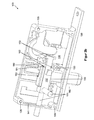
- FIG. 1 shows a part of a locking device 100 according to an embodiment of the invention.
- the locking device 100 has a housing 110, which consists essentially of two housing parts or halves 120, 130.
- the housing part 120 designed here as a housing cover has fastening openings 123, through which countersunk screws 101 are screwed to the other housing part 130.
- a forend 133 connects at the front side here by way of example of the housing part 130.
- an attachment opening 134 is provided here by way of example in order to attach the housing 110 or the housing Locking device 100 can be used in a known manner in a (door) wing stationary.
- the housing 110 is thus formed from the outside as a conventional door lock housing.
- a respective opening 121 or 131 is formed in each housing part 120, 130.
- the openings 121, 131 are used to pass through a handle 150 of the locking device 100 explained in more detail below and are shaped in accordance with its actuating or movement path, which will also be explained in more detail later.
- each housing part 120, 130 a respective opening 122 and 132.
- These openings 122, 132 now serve the passage of an exemplary used, but not shown here lock cylinder whose role will also be explained later.
- FIG. 2a shows the locking device 100 of FIG. 1 from view of the housing part 130, wherein the housing part 120 is not shown in this view. Further, the forend 133 is shown with its attachment opening 134.
- the gripping piece 150 has three sections 151, which project from a guide section 152 of the gripping piece 150 explained in more detail later.
- the right-hand grip section 151 passes through a second opening 141 formed in the front of the housing part 130.
- the openings 122 and 132 each have two locking receptacles 124, 125 and 139, 140. These serve the purpose of passing the passing handle portion 141 at a movement in the direction of each prevent other Arret istsaus Principleung 125, 124 and 140, 139. Ie. the handle 140 is locked in place in this regard.
- FIG. 2b shows the locking device 100 of FIG. 2a from the opposite side. Ie. Here is a part of the “inner life" of the locking device 100 can be seen.
- the housing part 130 has threaded bores 135 for the screws 101, not shown here, and two projection projections 136 projecting in the direction of the housing part 120, not shown. These engage in corresponding, not further explained insertion openings of the housing part 120, so that both housing parts 120, 130 are held in position for screwing each other.
- the aforementioned guide portion 152 of the handle 150 can be seen.
- the guide section 152 is received here in a guide groove 161 of a locking bolt 160 so as to be movable guided perpendicular to a direction of movement of the locking bolt 150.
- the guide section 152 has at its end remote from the left handle section 151 projections 153 which are formed or attached to the guide section 152 and away from it extend in opposite directions.
- the locking bolt 160 has stop surfaces 162 on a side facing the projections 153. If the handle 150 is pulled out in the direction of opening 141 from the housing 110, eventually reach the projections 153 with the abutment surfaces 162 in abutment, and the handle 150 can not be further moved out of the housing 150 out.
- transmission part 180 is pivotally mounted or rotatable or rotatable.
- the locking bolt 160 on its side facing the housing part 130 on a corner-like recess 163.
- the transmission part 180 is partially arranged.
- Figure 2c shows the locking device 100 of FIG. 2b in a different perspective and without transmission part 180.
- the locking bolt 160 On its side facing the housing part 130, the locking bolt 160 has a projection 164 projecting in the direction of the housing part 130. This is movably guided in a guide groove 137.
- the guide groove 137 is formed on the inner side of the housing part 130 facing the locking bolt 160, in that a wall section 138 is designed to protrude from this inner side by way of example.
- the wall portion 138 is formed so that the projection 164 and thus the locking pin 160 is guided in the direction in and out of a locking projection 165 of the locking bolt 160.
- the wall portion 138 may, as indicated here, be circumferentially formed. But he can only right and left side here the projection 164 may be formed.
- the guide groove 137 may be milled out of the housing part 130, for example.
- the housing part 130 also has an arcuate guide groove 168 on the aforementioned inner side. Their role is explained in more detail below.
- FIG. 3 shows the locking pin 160 and the transmission part 180 in greater detail and in one FIG. 2a similar perspective.
- the transmission part 180 has at its the projection 164 facing the end of a recess 181, which makes the end look like a fork. In this recess 181 of the projection 164 comes to rest.
- the projection 164 is shaped so that the transmission member 180 can pivot around the projection 164 without obstruction.
- the projection 164 thus has a dual function.
- he also forms the fulcrum for the transmission part 180th
- the recess 163 also makes it possible for the locking bolt, with its surface facing the housing part 130, to rest against the aforementioned inner side of the housing part 130 and thus be moved without play in the housing 110. This serves, for example, the purpose of avoiding rattling noises.
- the transmission part 180 is also formed like a fork at its end facing away from the projection 164, so here has a recess 183 on.
- the recess 183 is used to engage a Sch drunkbarts a lock cylinder, not shown.
- the lock cylinder is used in a known manner in the housing 110 stationary, in such a way that upon rotation of the Sch thoroughlybarts this engages in the recess 183 and further rotation to the recess 183 belonging end of the transmission part 180 entrains.
- the recess 183 thus represents a Mitaueraus principleung. So this entrainment is done so that the projection 164 along the guide groove 136 moves and thus corresponding to the locking projection 165 depending on the direction of rotation of the Schschschbarts in the housing 110 or out of this can move, has Transmission part 180 on its side facing the aforementioned groove 168 a guide projection 182 on.
- the guide projection 182 engages the guide groove 168 and follows its arcuate shape. Ie. the recess 183 is up in FIG. 3 entrained, the recess 183 remains due to the arch shape at the same distance from the axis of rotation of the Schschschbart. A deadlock can therefore not occur.
- the transfer member 180 is thus moved along the arcuate shape of the recess 168 about the axis of rotation of the lock bar, the recess 181 will accordingly move along a curved line of greater radius about the same axis of rotation.
- the projection 164 also up in FIG. 3 with, and the locking projection 165 is moved into the housing 11 inside.
- the recess 181 moves quasi but also on the projection 165. To avoid jamming here, the recess 181 is correspondingly deep.
- a recording 166 can be seen, which will be discussed later.
- FIG. 4a shows an exploded view concerning the arrangement transmission part 180, locking pin 160 and handle 150 of the locking device 100th
- the handle 150 has a groove-like and in cross-section by way of example semicircular recess 155, which extends in the direction of movement of the handle 150 along the extension of the right grip portion 151.
- a spring stop 154 At this left end of the recess 155 is a spring stop 154.
- the recess 155 thus forms a receptacle for a compression spring 102nd
- FIG. 4b also shows the locking pin 160 and the handle 150 in exploded view and from one with respect to FIG. 4a Back here.
- the locking bolt 160 also has a preferably semicircular recess 170 in cross-section, which extends parallel to the recess 155 in the assembled state and forms a receiving channel with a round cross-section with this.
- a spring stop 169th At the stop surface 156 of the handle 150 facing the end of the recess 170 is now on the locking pin 160, a spring stop 169th
- the spring 102 is received in the channel 155, 170 and clamped between the spring stops 154, 169. This has the consequence that the spring 102 acts as a compression spring and thus the handle 150 in Direction of a stop surface 171 of the locking bolt 160 and thus into the housing 110 is urging.
- the handle 150 is urged in the direction of locking the respective position, so that the locking pin 160 is securely held in the corresponding position.
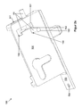
- FIG. 5a shows a wing 10, which is equipped with such a locking device 100.
- the handle 150 has only one grip portion 151.
- the wing 10 has a breakthrough 11 corresponding to the opening 121 of the locking device 100, through which the grip section 151 passes.
- the opening 11 includes locking recesses 15, 16.
- the locking device 100 is fixed by means of the aforementioned screw 101 and the mounting hole 134 in the forend 133 on the wing 10.
- the wing 10 For receiving the locking device 100, the wing 10 has a corresponding receiving opening 12.
- the locking projection 165 of the locking bolt 160 exemplarily looks out of the lower edge of the wing 10.
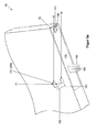
- FIG. 5b shows the wing 10 from one to FIG. 5b essentially opposite perspective.
- the rotary knob 103 is provided with a lock bit or non-rotatably connected, as described above. Ie. the rotation of the knob 103 causes the locking projection 165 to move in or out into the wing 10 or out of it.
- the knob 103 is a safety knob. Ie. this couples with the lock only when a person has authenticated in a known manner, for example by means of an RFID card.
- the locking device 100 is readily applicable to wings that must be secured from one side of the respective wing forth against unauthorized opening, as is the case for example at the entrance doors of shops.
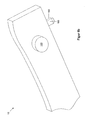
- FIG. 6 shows a wing system 1, with the wing 10 of FIG. 5 is provided.
- the wing 10 is formed by way of example as a frame door leaf, thus has a glass panel 14 which is surrounded by a peripheral frame profile 13 and held therein.
- a locking device 100 is arranged in the lower, horizontally extending part of the frame profile 13. In the area of the wing 10 is shown cut. The locking device 100 is arranged or received in the already mentioned recess 12 of the wing 10.
- the locking device 100 is shown in the locking position, in which the wing 10 is prevented from moving. In this position, the locking projection 165 engages in a locking receptacle 3 formed in the bottom 2.
- the locking receptacle 3 can be formed, for example, by means of a sunk in the bottom 2 ground sleeve.
- the locking device 100 may include a housing of any shape.
- the form of a door lock housing has the advantage that standard dimensions already exist for this, which make it easy to use the locking device 100.
- an opening 121, 131, 141 or, 141, 132, 122 need only be formed on one side.
- the breakthrough 11; 121; 131 can without locking recesses 15, 16; 124, 125; 139, 150 or only be provided with one each.
- the locking bolt 100 could have on one side, which faces an inner side of the housing 110, a spring-loaded detent ball, which engages in the respective end position in a corresponding recess in just inside of the housing 110.
- the breakthrough 11; 121; 131 does not have to be square.
- the transition to the respective locking recess 15, 16; 124, 125; 139, 150 may by means of a slope and / or each rounded Be formed corners. This makes it possible to move the locking projection 165 also by means of rotating the transmission part 180 from one end position to the other, even if the handle 151 in a respective Arret istsaus Principleung 15, 16; 124, 125; 139, 150 has come to rest.
- the locking projection 165 engages in the locking position in a corresponding receiving a sash. This is useful, for example, in toilet revolving doors, which are conventionally internally by means of a handle or the like, d. H. without tools, to lock and unlock. However, if an emergency occurs, in which a person needs help, but is no longer able to leave the toilet, an authorized person from the outside, for example, the above-mentioned RFID card access to the toilet and help the person concerned ,
- the locking projection 165 engages in the locking position in a corresponding receptacle of an opposing wing 10. Ie. multi-leaf door systems can be locked without further ado.
- the housing 110 can be assembled in any way, for example by means of latching, jamming, gluing or the like. The same applies to the insertion in the wing 10.
- the forend 133 is also not required, if a different type of attachment of the housing 110 is provided.
- the housing 110 may also be placed on the wing 10.
- the locking pin 160 may also have two projections 164 instead of one. This would make a technical degree possible. In that case, the path of movement of the handle 150 would have to be adjusted.
- the handle must have only one handle portion 151. But it can also be several.
- the lock cylinder can be replaced by a lock nut, so that a doorknob can be used.
- the locking bolt 160 may be configured so that its locking portion 165 has the shape of a door latch.
- the locking bolt is then biased in the direction of locking position. This makes it possible to use the locking device as a replacement for wing locks, which do not have a lock bolt. This is the case, for example, for doors within a building.
- the advantage is that these doors can also be retroactively provided with the function that the underlying space can only be entered by authorized persons. And since the housing 110 can be adapted to the shape of such a lock, no further changes to the door system, apart from the replacement of the door lock by a locking device according to the invention, are required.
- the locking device 100 is applicable to any type of wing 10 and wing system 1, which has a wing 10 to be locked and thus necessarily movable. Suitable wings are accordingly window sash, door leaf, partition modules, etc.
- a space-saving, simple design, low-cost, universally applicable and easy-to-install wing lock is created by the invention, the locking and unlocking of a relevant wing from one side without tools and from the other side with tools such as keys, RFID card, etc .. . allows. Ie. the wing can be used, for example, in escape routes, without the security being reduced in the direction opposite to the direction of escape.
Landscapes
- Engineering & Computer Science (AREA)
- Mechanical Engineering (AREA)
- Structural Engineering (AREA)
- Business, Economics & Management (AREA)
- Emergency Management (AREA)
- Lock And Its Accessories (AREA)
Applications Claiming Priority (1)
| Application Number | Priority Date | Filing Date | Title |
|---|---|---|---|
| DE201210012415 DE102012012415A1 (de) | 2012-06-25 | 2012-06-25 | Verriegelungsvorrichtung und damit ausgestattete Flügel bzw. Flügelanlage |
Publications (2)
| Publication Number | Publication Date |
|---|---|
| EP2679751A2 true EP2679751A2 (fr) | 2014-01-01 |
| EP2679751A3 EP2679751A3 (fr) | 2017-09-06 |
Family
ID=48577465
Family Applications (1)
| Application Number | Title | Priority Date | Filing Date |
|---|---|---|---|
| EP13002749.3A Withdrawn EP2679751A3 (fr) | 2012-06-25 | 2013-05-28 | Dispositif de verrouillage et battant ou installation de battant équipé de celui-ci |
Country Status (3)
| Country | Link |
|---|---|
| US (1) | US20130340492A1 (fr) |
| EP (1) | EP2679751A3 (fr) |
| DE (1) | DE102012012415A1 (fr) |
Cited By (1)
| Publication number | Priority date | Publication date | Assignee | Title |
|---|---|---|---|---|
| DE102017004422A1 (de) * | 2017-06-09 | 2018-12-13 | Günter Feise | Sicherheitsriegel / für Außentüren |
Families Citing this family (4)
| Publication number | Priority date | Publication date | Assignee | Title |
|---|---|---|---|---|
| CN105442946B (zh) * | 2015-12-28 | 2018-07-03 | 德施曼机电(中国)有限公司 | 一种门栓式智能门锁 |
| US12049772B2 (en) | 2019-01-11 | 2024-07-30 | Assa Abloy New Zealand Limited | Lock assembly |
| WO2022011291A1 (fr) * | 2020-07-10 | 2022-01-13 | Spectrum Brands, Inc. | Pêne dormant coulissant |
| US20250002153A1 (en) * | 2023-06-29 | 2025-01-02 | B/E Aerospace, Inc. | Premium and accessible lavatory with increased door opening |
Family Cites Families (49)
| Publication number | Priority date | Publication date | Assignee | Title |
|---|---|---|---|---|
| US2002619A (en) * | 1933-10-27 | 1935-05-28 | Sargent & Co | Doorlock |
| US2301557A (en) * | 1938-01-28 | 1942-11-10 | Hancock Mfg Company | Locking device |
| US2380708A (en) * | 1943-07-12 | 1945-07-31 | Schlage Lock Co | Door lock |
| US2628117A (en) * | 1948-12-22 | 1953-02-10 | Stanley Works | Latch operating mechanism |
| US2638771A (en) * | 1949-12-14 | 1953-05-19 | Engineered Products Company | Door latch |
| US2695805A (en) * | 1951-07-27 | 1954-11-30 | Wheeling Steel Corp | Latch and latch bolt |
| US2917915A (en) * | 1955-06-06 | 1959-12-22 | American Hardware Corp | Folding door lock |
| US2895322A (en) * | 1955-06-10 | 1959-07-21 | Hauserman Co E F | Door lock |
| US2986919A (en) * | 1955-10-14 | 1961-06-06 | Hensel Erich | Mounting arrangement for lock mechanism |
| US3103806A (en) * | 1960-08-01 | 1963-09-17 | Ellis | Safety deposit box lock |
| US3157043A (en) * | 1961-09-29 | 1964-11-17 | Ellis | Safe deposit box lock |
| US3306086A (en) * | 1964-08-24 | 1967-02-28 | Nat Lock Co | Garage door locks |
| US3672714A (en) * | 1970-09-28 | 1972-06-27 | Eaton Corp | Mortise lock with multiple functions |
| US3783658A (en) * | 1972-02-23 | 1974-01-08 | W Wada | Door lock |
| DE2239390A1 (de) * | 1972-08-10 | 1974-02-21 | Schuermann & Co Heinz | Einsteckschloss fuer tueren |
| US3877739A (en) * | 1974-02-22 | 1975-04-15 | Ram Partitions Ltd | Door latch |
| US4118056A (en) * | 1977-04-04 | 1978-10-03 | Emhart Industries, Inc. | Mortise lock |
| US4182528A (en) * | 1977-08-30 | 1980-01-08 | Klay William F | Door lock |
| FI76620C (fi) * | 1981-03-25 | 1988-11-10 | Waertsilae Oy Ab | Flerfunktionslaos. |
| US4640112A (en) * | 1983-08-08 | 1987-02-03 | R. R. Brink Locking Systems, Inc. | Security door knob and escutcheon |
| US4580423A (en) * | 1983-11-03 | 1986-04-08 | Keystone Consolidated Industries, Inc. | Garage door lock mechanism |
| US4691543A (en) * | 1985-03-18 | 1987-09-08 | Watts John R | Deadlock with key operated locking cylinder |
| GB8908386D0 (en) * | 1989-04-13 | 1989-06-01 | Chubb Lips Nederland Bv | Locks |
| AU7004494A (en) * | 1993-06-29 | 1995-01-24 | European Lock Company Limited | Improvements in locks |
| US5713227A (en) * | 1996-05-06 | 1998-02-03 | Turnbo; William A. | Lever activated dead-bolt lock |
| US5813255A (en) * | 1996-09-25 | 1998-09-29 | Pdq Industries, Inc. | Lock mechanism with closed case changeovers |
| US5947535A (en) * | 1996-10-18 | 1999-09-07 | Baker; John R. | Dual motion, quick release latch mechanism |
| US5820177A (en) * | 1997-05-01 | 1998-10-13 | Winfield Locks, Inc. | Automatic deadbolt |
| FR2767854B1 (fr) * | 1997-09-02 | 2000-06-23 | Gunnebo Troax Ab | Serrure de portes d'enceintes industrielles |
| US5992195A (en) * | 1999-01-15 | 1999-11-30 | Sargent Manufacturing Corporation | Lever handle controller for mortise lock |
| DE10013487C2 (de) * | 2000-03-20 | 2002-12-19 | Emka Beschlagteile | Verschlußvorrichtung für Türen von Gehäusen mit insbesondere schmalen Rahmenprofilen |
| US6393878B1 (en) * | 2000-05-22 | 2002-05-28 | Corbin Russwin, Inc. | Mortise lock |
| AUPR604601A0 (en) * | 2001-06-29 | 2001-07-26 | Gainsborough Hardware Industries Limited | A mortice lock |
| US7013687B2 (en) * | 2002-04-30 | 2006-03-21 | Haworth, Ltd. | Sliding door lock with single lock-release and door-opening motion |
| NZ521338A (en) * | 2002-09-12 | 2005-02-25 | Assa Abloy Financial Services | A lock mechanism |
| GB2406876B (en) * | 2003-09-30 | 2005-11-30 | Colin Sidney Middleton | Improvements in locks |
| US7188870B2 (en) * | 2004-03-26 | 2007-03-13 | Sargent Manufacturing Company | Multi-functional mortise lock |
| US7249477B2 (en) * | 2004-07-16 | 2007-07-31 | Von Duprin, Inc. | Control for exit device |
| US20070194576A1 (en) * | 2006-02-03 | 2007-08-23 | John D Esposito | Heavy duty door handle and lock apparatus |
| US7926315B2 (en) * | 2006-09-19 | 2011-04-19 | Imperial USA, Ltd | Lock assembly with anti-panic feature and associated method |
| TW200815654A (en) * | 2006-09-21 | 2008-04-01 | Door & Amp Window Hardware Co | Locking device for frameless glass door |
| US20080211239A1 (en) * | 2007-03-02 | 2008-09-04 | Jon Edward Keller | Security improvement to solenoid-releasable mortise lockset having thumb-lever actuators |
| US20090100883A1 (en) * | 2007-10-19 | 2009-04-23 | Larson Manufacturingi Company | Mortise deadbolt lock cam engagement device |
| TWM392228U (en) * | 2009-09-04 | 2010-11-11 | miao-xue Cai | Door lock using a key to control transmission mechanism |
| CN102648324B (zh) * | 2009-11-10 | 2015-05-13 | 盖恩斯伯勒硬件工业有限公司 | 锁具组件 |
| US8419086B2 (en) * | 2010-07-14 | 2013-04-16 | Townsteel, Inc. | Mortise latchset with dually biased cam assembly |
| US20120137742A1 (en) * | 2010-12-07 | 2012-06-07 | Securistyle Limited | Locking Device and Associated Methods |
| US8839562B2 (en) * | 2011-10-24 | 2014-09-23 | Schlage Lock Company | Mortise lock assembly and method of assembling |
| US9169666B2 (en) * | 2012-01-05 | 2015-10-27 | Yale Security Inc. | Door latch operator apparatus |
-
2012
- 2012-06-25 DE DE201210012415 patent/DE102012012415A1/de not_active Withdrawn
-
2013
- 2013-05-28 EP EP13002749.3A patent/EP2679751A3/fr not_active Withdrawn
- 2013-06-24 US US13/925,463 patent/US20130340492A1/en not_active Abandoned
Non-Patent Citations (1)
| Title |
|---|
| None |
Cited By (1)
| Publication number | Priority date | Publication date | Assignee | Title |
|---|---|---|---|---|
| DE102017004422A1 (de) * | 2017-06-09 | 2018-12-13 | Günter Feise | Sicherheitsriegel / für Außentüren |
Also Published As
| Publication number | Publication date |
|---|---|
| US20130340492A1 (en) | 2013-12-26 |
| EP2679751A3 (fr) | 2017-09-06 |
| DE102012012415A1 (de) | 2014-03-27 |
Similar Documents
| Publication | Publication Date | Title |
|---|---|---|
| EP3309333B1 (fr) | Système comprenant un châssis dormant destiné à loger un cadre de vantail | |
| EP2679751A2 (fr) | Dispositif de verrouillage et battant ou installation de battant équipé de celui-ci | |
| EP2796645B1 (fr) | Serrure à pêne dormant d'un meuble | |
| DE102019100639B3 (de) | Türbedienanordnung sowie Tür | |
| DE102015001960A1 (de) | Schliesszylinder mit zwei auf gleicher Achse beabstandet zueinander angeordneten Schliessnasen | |
| EP2752537A2 (fr) | Agencement de ferrure | |
| DE102012001787A1 (de) | Türöffner und Tür mit Türöffner | |
| EP3095934B1 (fr) | Dispositif de detection d'une position de verrou | |
| EP2862992B1 (fr) | Multi-serrure | |
| EP3165696A1 (fr) | Serrure comprenant un fouillot débrayable | |
| DE19743655C2 (de) | Schließvorrichtung für ein Schloß | |
| EP0930410B1 (fr) | Poignée de manoeuvre | |
| EP2738324B1 (fr) | Serrure dotée d'une unité de rotation débloquable | |
| DE102004060477B4 (de) | Schließzylinder | |
| WO2007104295A1 (fr) | Serrure pour une porte de maison ou d'appartement | |
| DE29506799U1 (de) | Vorrichtung an einem Türschloß | |
| DE29923398U1 (de) | Schließsystem für Möbel | |
| DE202015001220U1 (de) | Schließzylinder mit zwei auf gleicher Achse beabstandet zueinander angeordneten Schließnasen | |
| EP2620572B1 (fr) | Dispositif de verrouillage pour le blocage d'un mouvement d'un battant par rapport à un cadre | |
| DE19507481C1 (de) | Abschließbarer Fenstergriff | |
| DE102018117858A1 (de) | Verriegelungsvorrichtung für einen Treibstangenbeschlag | |
| EP1338733B1 (fr) | Serrure cylindrique | |
| DE19836927C2 (de) | Sperrvorrichtung zum Kuppeln eines Griffelementes mit einem Dorn eines Schlosses | |
| EP3892802B1 (fr) | Agencement de poignée de porte | |
| DE19738243C2 (de) | Schloß für Sicherheitstüren |
Legal Events
| Date | Code | Title | Description |
|---|---|---|---|
| PUAI | Public reference made under article 153(3) epc to a published international application that has entered the european phase |
Free format text: ORIGINAL CODE: 0009012 |
|
| AK | Designated contracting states |
Kind code of ref document: A2 Designated state(s): AL AT BE BG CH CY CZ DE DK EE ES FI FR GB GR HR HU IE IS IT LI LT LU LV MC MK MT NL NO PL PT RO RS SE SI SK SM TR |
|
| AX | Request for extension of the european patent |
Extension state: BA ME |
|
| RAP1 | Party data changed (applicant data changed or rights of an application transferred) |
Owner name: DORMA DEUTSCHLAND GMBH |
|
| PUAL | Search report despatched |
Free format text: ORIGINAL CODE: 0009013 |
|
| AK | Designated contracting states |
Kind code of ref document: A3 Designated state(s): AL AT BE BG CH CY CZ DE DK EE ES FI FR GB GR HR HU IE IS IT LI LT LU LV MC MK MT NL NO PL PT RO RS SE SI SK SM TR |
|
| AX | Request for extension of the european patent |
Extension state: BA ME |
|
| RIC1 | Information provided on ipc code assigned before grant |
Ipc: E05B 9/02 20060101ALI20170803BHEP Ipc: E05B 63/16 20060101AFI20170803BHEP Ipc: E05B 1/00 20060101ALI20170803BHEP Ipc: E05C 1/06 20060101ALI20170803BHEP Ipc: E05B 47/00 20060101ALN20170803BHEP Ipc: E05B 15/10 20060101ALN20170803BHEP Ipc: E05B 65/10 20060101ALI20170803BHEP Ipc: E05B 47/06 20060101ALN20170803BHEP Ipc: E05B 65/08 20060101ALI20170803BHEP |
|
| STAA | Information on the status of an ep patent application or granted ep patent |
Free format text: STATUS: REQUEST FOR EXAMINATION WAS MADE |
|
| 17P | Request for examination filed |
Effective date: 20180306 |
|
| RBV | Designated contracting states (corrected) |
Designated state(s): AL AT BE BG CH CY CZ DE DK EE ES FI FR GB GR HR HU IE IS IT LI LT LU LV MC MK MT NL NO PL PT RO RS SE SI SK SM TR |
|
| STAA | Information on the status of an ep patent application or granted ep patent |
Free format text: STATUS: THE APPLICATION IS DEEMED TO BE WITHDRAWN |
|
| 18D | Application deemed to be withdrawn |
Effective date: 20180307 |