EP1777795A2 - Dispositif polaire avec aimants permanents - Google Patents
Dispositif polaire avec aimants permanents Download PDFInfo
- Publication number
- EP1777795A2 EP1777795A2 EP06253232A EP06253232A EP1777795A2 EP 1777795 A2 EP1777795 A2 EP 1777795A2 EP 06253232 A EP06253232 A EP 06253232A EP 06253232 A EP06253232 A EP 06253232A EP 1777795 A2 EP1777795 A2 EP 1777795A2
- Authority
- EP
- European Patent Office
- Prior art keywords
- pole
- laminations
- assembly
- base plate
- rotor
- Prior art date
- Legal status (The legal status is an assumption and is not a legal conclusion. Google has not performed a legal analysis and makes no representation as to the accuracy of the status listed.)
- Granted
Links
- 238000003475 lamination Methods 0.000 claims abstract description 101
- 239000000463 material Substances 0.000 claims description 23
- 230000000712 assembly Effects 0.000 claims description 14
- 238000000429 assembly Methods 0.000 claims description 14
- 229910000976 Electrical steel Inorganic materials 0.000 claims description 9
- 239000002131 composite material Substances 0.000 claims description 6
- 230000008878 coupling Effects 0.000 claims description 5
- 238000010168 coupling process Methods 0.000 claims description 5
- 238000005859 coupling reaction Methods 0.000 claims description 5
- 239000011347 resin Substances 0.000 claims description 2
- 229920005989 resin Polymers 0.000 claims description 2
- 229910000831 Steel Inorganic materials 0.000 claims 1
- 230000005294 ferromagnetic effect Effects 0.000 claims 1
- 239000010959 steel Substances 0.000 claims 1
- 238000000034 method Methods 0.000 description 7
- 239000004593 Epoxy Substances 0.000 description 6
- 230000004907 flux Effects 0.000 description 5
- 230000001360 synchronised effect Effects 0.000 description 5
- 230000002159 abnormal effect Effects 0.000 description 4
- 239000011324 bead Substances 0.000 description 4
- 239000011152 fibreglass Substances 0.000 description 4
- 238000004891 communication Methods 0.000 description 3
- 239000000805 composite resin Substances 0.000 description 3
- 230000005291 magnetic effect Effects 0.000 description 3
- 239000000696 magnetic material Substances 0.000 description 3
- 239000007767 bonding agent Substances 0.000 description 2
- 239000003302 ferromagnetic material Substances 0.000 description 2
- 229920000728 polyester Polymers 0.000 description 2
- 239000004925 Acrylic resin Substances 0.000 description 1
- 229920000178 Acrylic resin Polymers 0.000 description 1
- 239000011230 binding agent Substances 0.000 description 1
- 238000006243 chemical reaction Methods 0.000 description 1
- 230000005347 demagnetization Effects 0.000 description 1
- 238000005470 impregnation Methods 0.000 description 1
- 230000006698 induction Effects 0.000 description 1
- 239000006247 magnetic powder Substances 0.000 description 1
- 239000000843 powder Substances 0.000 description 1
- 238000007493 shaping process Methods 0.000 description 1
- 238000004804 winding Methods 0.000 description 1
Images


Classifications
-
- H—ELECTRICITY
- H02—GENERATION; CONVERSION OR DISTRIBUTION OF ELECTRIC POWER
- H02K—DYNAMO-ELECTRIC MACHINES
- H02K1/00—Details of the magnetic circuit
- H02K1/06—Details of the magnetic circuit characterised by the shape, form or construction
- H02K1/22—Rotating parts of the magnetic circuit
- H02K1/27—Rotor cores with permanent magnets
- H02K1/2706—Inner rotors
- H02K1/272—Inner rotors the magnetisation axis of the magnets being perpendicular to the rotor axis
- H02K1/274—Inner rotors the magnetisation axis of the magnets being perpendicular to the rotor axis the rotor consisting of two or more circumferentially positioned magnets
- H02K1/2753—Inner rotors the magnetisation axis of the magnets being perpendicular to the rotor axis the rotor consisting of two or more circumferentially positioned magnets the rotor consisting of magnets or groups of magnets arranged with alternating polarity
- H02K1/276—Magnets embedded in the magnetic core, e.g. interior permanent magnets [IPM]
Definitions
- This invention relates generally to permanent magnet machines, and more particularly, methods and apparatus for assembling a permanent magnet pole assembly for an electric machine.
- At least some known high-torque, low-speed permanent magnet machines used with electric utility class wind generators and other applications include large diameter rotors having a diameter greater than one meter. Such rotors generally include many magnet poles. Known magnet poles are assembled from multiple magnetic blocks that are secured to the rotor. However, such designs generally do not adequately address magnet pole design issues including rotor losses, demagnetization protection, pole shaping, pole assembly, permanent magnet block capture, magnetized pole handling and/or pole mounting of a magnetized pole.
- At least some known brushless AC synchronous permanent magnet machines may include necessary, but undesirable non-synchronous air gap flux caused by harmonics and/or sub-harmonics in the armature reaction, or by slotting. This non-synchronous flux induces eddy current loss in electrically conducting components of the rotor. Stators constructed with fractional slot windings e.g., 2/5 or 2/7 slots per pole per phase, are particularly problematic in creating non-synchronous air-gap flux, and resulting rotor losses. To facilitate preventing such rotor losses, at least some known machines utilize bonded magnets, which include magnetic powder embedded in a polymeric binder. However, the residual induction of bonded magnets is generally very low, especially for high torque machines.
- magnet poles Some rotors secure the magnets to the rotor of an interior rotor machine using a fiberglass hoop that is wet wound around the magnets. On at least some rotors the magnets are held to the motor by shrunk fit metallic hoops. With this approach, the magnets are typically magnetized after they are coupled to the rotor, before the rotor is positioned relative to the stator.
- Other known magnet poles are magnetized prior to being inserted into an air gap defined between the pre-assembled rotor and stator. Such poles are then secured in place with separate clamping pieces. However, because the clamps are separate pieces from the magnet pole, the clamping process may be time-consuming.
- a pole assembly for a rotor includes a permanent magnet pole including at least one permanent magnet block, a plurality of laminations including a pole cap mechanically coupled to the pole, and a plurality of laminations including a base plate mechanically coupled to the pole.
- a method for assembling a pole assembly for a rotor includes coupling a plurality of clamping bars to the rotor and coupling a plurality of base plate laminations to the rotor.
- the method also includes coupling a plurality of pole cap laminations to the clamping bars such that a cavity is defined between the plurality of base plate laminations and the plurality of pole cap laminations and inserting a plurality of permanent magnet blocks into the cavity.
- an electric machine in a further aspect of the invention, includes a stator assembly and a rotor assembly rotatably coupled with the stator assembly.
- the stator assembly and the rotor assembly are separated from one another by an air gap.
- the rotor assembly includes a plurality pole assemblies, each pole assembly includes a plurality unitary pole laminations.
- the pole laminations include a laminated base plate portion, a laminated pole cap portion, and a laminated bridge portion extending therebetween such that a cavity is formed between the laminated base plate portion and the laminated pole cap portion.
- the pole assembly also includes a permanent magnet pole including a plurality of sintered magnet blocks coupled within the cavity such that the pole is enclosed with the plurality of pole laminations and a coupling member configured to secure the pole assembly to the rotor assembly.
- the present invention is directed to permanent magnet (PM) pole assemblies for use with high pole count electric machines that are particularly useful for low speed drives, such as direct-drive multi-megawatt wind generators and ship propulsion motors. While the invention is described and illustrated in the context of a radial flux, synchronous electrical machine, the invention is not limited to such electrical machines.
- the embodiments set forth herein are therefore exemplary only and represents various embodiments of the invention, but are not conclusive of all embodiments. As explained below, these embodiments contribute towards reducing rotor eddy current losses, cogging torque, and ripple torque, in electric machines, as well as, facilitating the protection of such against de-magnetization machines, while also providing a means to secure the pole to the rotor rim.
- the attachment means is such that the pole pieces, in either a magnetized or un-magnetized state, can be individually inserted and extracted from the air gap by sliding the pole axially.
- Figure 1 is a prospective view of an exemplary permanent magnet rotor assembly 10 for an electrical machine (not shown) including a rotor 12 and a plurality of permanent magnet pole assemblies 14 coupled to rotor 12 by a plurality of retaining clamps 16.
- Figure 2 is an exploded prospective view of rotor assembly 10 including pole assembly 14, a plurality of retaining clamps 16, and a rotor rim 18.
- Figure 3 is a prospective view of a first embodiment of permanent magnet pole assembly 14.
- pole assembly 14 includes a plurality of base plate laminations 20, plurality of pole caps laminations 30, and a permanent magnet pole 40 mechanically coupled therebetween. Base plates 20, pole caps 30, and pole 40 are bonded together with a bonding agent that is impregnated between all the components.
- Base plate laminations 20 are configured to facilitate reducing eddy current losses.
- each base plate lamination 20 is substantially rectangular in shape.
- each base plate lamination 20 may have any other shape, such as, but not limited to, an arcuate shape or a trapezoidal shape.
- each base plate lamination 20 is contoured with a shape that substantially matches a contour of stator rim (not shown).
- base plate laminations 20 are fabricated from a laminated ferromagnetic material.
- base plate laminations 20 may be fabricated from any other suitable material, such as a soft magnetic composite material, that enables pole assembly 14 to function as described herein.
- Each base plate lamination 20 includes a first sidewall 22, a second sidewall 24, a third sidewall 26, and a fourth sidewall 28.
- second sidewall 24 and fourth sidewall 28 are substantially parallel to one another.
- first and third sidewalls 22 and 26 respectively are substantially perpendicular to second and fourth sidewalls 24 and 28.
- Pole cap laminations 30 are shaped to facilitate minimizing cogging torque and to facilitate protecting permanent magnet pole 40 from demagnetizing fields under abnormal conditions.
- each pole cap lamination 30 is substantially trapezoidal in shape.
- each pole lamination 30 may have any other shape, such as, but not limited to, a rectangular shape or an arcuate shape.
- each pole cap lamination 30 has a contour that substantially matches a contour of stator rim (not shown).
- each pole cap lamination 30 is fabricated from an electrical steel material.
- pole cap laminations 30 may be fabricated from any other suitable material that enables pole assembly 14 to function as described herein.
- Each pole cap lamination 30 includes a first sidewall 32 and a second sidewall 34, first and second sidewalls 32 and 34 respectively are substantially parallel.
- each pole cap lamination 30 includes a first tapered portion 36 extending from sidewall 34 towards sidewall 32 and a second tapered portion 38 extending from sidewall 34 towards sidewall 32.
- Permanent magnet pole 40 includes permanent magnet blocks 42 which are coupled between base plate laminations 20 and pole cap laminations 30.
- PM pole 40 includes a plurality of magnet blocks 42 that do not extend the length of the pole assembly 14, but rather includes a plurality of magnet blocks 42 stacked together to achieve a desired length of pole assembly 14.
- each permanent magnet block 42 is substantially rectangular in shape.
- permanent magnet block 42 may have any other shape, such as, but not limited to, a square shape or a trapezoidal shape.
- each PM pole 40 has a contour that substantially matches a contour of both base plate sidewall 22 and pole cap sidewall 32.
- each PM pole 40 is fabricated from six sintered block magnets 42 and coated with an electrically-isolating epoxy.
- PM pole 40 may be fabricated from any other suitable block magnets and coated with any other suitable epoxy that enables pole assembly 14 to function as described herein.
- pole assembly 14 is magnetized and then mounted on to rotor 12 being coupled to a stator (not shown). In an alternative embodiment, pole assembly 14 is coupled to rotor 12, magnetized, and the resulting magnetized pole assembly 14 then coupled to the stator.
- Figure 4 is a cross-sectional view of a second embodiment of pole assembly 50.
- Permanent magnet pole assembly 50 is substantially similar to pole assembly 14, (shown in Figure 3) and components of pole assembly 50 that are identical to components of pole assembly 14 are identified in Figure 4 using the same reference numerals used in Figure 3.
- pole assembly 50 includes a pair of clamping bars 100 which are mechanically coupled to a plurality of base plate laminations 200, a plurality of pole cap laminations 300, and a permanent magnet pole 40.
- Clamping bars 100, base plate laminations 200, pole cap laminations 300, and permanent magnet pole 40 are bonded together with a bonding agent that is impregnated between all the components.
- Base plate laminations 200 are configured to facilitate reducing eddy current losses.
- each base plate lamination 200 is substantially rectangular in shape.
- each base plate lamination 200 may have any other shape, such as, but not limited to, an arcuate shape or a trapezoidal shape.
- each base plate lamination 200 is contoured with a shape that substantially matches a contour of stator rim (not shown).
- base plate laminations 200 are fabricated from a laminated ferromagnetic material.
- base plate laminations 200 may be fabricated from any other suitable material, such as a soft magnetic composite material, that enables pole assembly 50 to function as described herein.
- Base plate laminations 200 include both truncated base plate laminations 201 and full-length base plate laminations 203.
- Full-length base plate laminations 203 couple axially between adjacent clamping bars 100 between mounting apertures 114.
- Truncated base plate laminations 201 extend axially between clamping bars 100 and are adjacent each mounting aperture 114.
- full-length base plate laminations 203 have a length L 1 and truncated base plate laminations 201 have a length L 2 , wherein L 1 is greater than L 2 .
- Each base plate lamination 200 includes a first sidewall 202, a second sidewall 204, a third sidewall 206, and a fourth sidewall 208.
- second sidewall 204 and fourth sidewall 208 are substantially parallel to one another.
- first sidewall 202 is substantially perpendicular to second and fourth sidewalls 204 and 208.
- each sidewall 202 includes a pair dovetails 210 extending substantially perpendicular from sidewall 202.
- Each dovetail 210 extends across substantially a full width of sidewall 202. Dovetails 210 slidably couple into dovetails slots 112 to facilitate securing each base plate lamination 200 upon one another within clamping bar 100 until a desired length of pole assembly 50 is achieved.
- each sidewall 206 includes a channel 220 extending partially therethrough and extending substantially across a full width of sidewall 206.
- Channel 220 receives a weld bead 222 therein.
- weld bead 222 is applied axially along an entire length of pole assembly 50 within channel 220.
- Pole cap laminations 300 are shaped to facilitate minimizing cogging torque and to facilitate protecting PM blocks 40 from demagnetizing fields under abnormal conditions.
- each pole cap lamination 300 is substantially trapezoidal in shape.
- each pole cap lamination 300 may have any other shape, such as, but not limited to, a rectangular shape or an arcuate shape.
- each pole cap lamination 300 has a contour that substantially matches a contour of stator rim (not shown).
- each pole cap lamination 300 is fabricated from an electrical steel material.
- pole cap lamination 300 may be fabricated from any other suitable material that enables pole assembly 50 to function as described herein.
- Each pole cap lamination 300 includes a first sidewall 302, a second sidewall 304, a third sidewall 306, and a fourth sidewall 308.
- First and third sidewalls 302 and 306 respectively are substantially parallel
- second and fourth sidewalls 304 and 308 respectively are substantially parallel.
- sidewalls 302 and 306 are substantially perpendicular to sidewalls 304 and 308.
- each sidewall 306 includes a tapered portion 320 extending from sidewall 306 towards sidewalls 304 and 308, respectively.
- sidewalls 304 and 308 each include a dovetail 310 extending substantially perpendicularly from sidewall 304.
- Each dovetail 310 extends substantially across a full width of sidewalls 304 and 308, respectively.
- Dovetails 310 slidably couple with dovetails slots 110 such that each pole cap lamination 300 is stacked upon one another within clamping bar 100 until a desired length of pole assembly 50 is achieved.
- a cavity 330 is defined by clamping bar sidewalls 102, base plate sidewalls 202, and pole cap sidewalls 302.
- Cavity 330 extends substantially across a full length of pole assembly 50.
- cavity 330 is substantially rectangular in shape.
- cavity 330 may have any other shape, such as, but not limited to, a square shape or a trapezoidal shape.
- Permanent magnet pole 40 includes permanent magnet blocks 42 which are slidably coupled within pole assembly cavity 330. Permanent magnet pole 40 includes a plurality of magnet blocks 42 that do not extend the length of the pole assembly 50, but rather includes a plurality of magnet blocks 42 stacked together to achieve a desired length of pole assembly 50.
- each permanent magnet block 42 is substantially rectangular in shape.
- permanent magnet block 42 may have any other shape, such as, but not limited to, a square shape or a trapezoidal shape.
- each pole 40 has a contour that substantially matches a contour of cavity 330.
- each PM pole 40 is fabricated from two sintered magnet blocks 42 and coated with an electrically-isolating epoxy.
- PM pole 40 may be fabricated from any other suitable magnet blocks and coated with any other suitable epoxy that enables pole assembly 50 to function as described herein.
- pole assembly 50 is fabricated from a conventional vacuum pressure impregnation resin such as, but not limited to an epoxy, a polyester, and an acrylic resin. Pole assembly 50 is then powder coated with a material such as, but not limited to, an epoxy and an epoxy-polyester. In one embodiment, pole assembly 50 is magnetized and then mounted on to rotor core 18 prior to being coupled to the stator. In an alternative embodiment, pole assembly 50 is coupled to rotor core 18, magnetized, and the resulting magnetized pole assembly 50 then coupled to the stator.
- a conventional vacuum pressure impregnation resin such as, but not limited to an epoxy, a polyester, and an acrylic resin. Pole assembly 50 is then powder coated with a material such as, but not limited to, an epoxy and an epoxy-polyester.
- pole assembly 50 is magnetized and then mounted on to rotor core 18 prior to being coupled to the stator. In an alternative embodiment, pole assembly 50 is coupled to rotor core 18, magnetized, and the resulting magnetized pole assembly 50 then coupled to the stator.
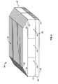
- FIG 5 is a cross-sectional view of a third embodiment of a permanent magnet pole assembly 70.
- Permanent magnet pole assembly 70 is substantially similar to pole assembly 50, (shown in Figure 4) and components of pole assembly 70 that are identical to components of pole assembly 50 are identified in Figure 5 using the same reference numerals used in Figure 4.
- pole assembly 70 includes a plurality of laminations 500 that are each sized to receive at least one permanent magnet pole 40 including permanent magnet blocks 42 therethrough. Moreover, laminations 500 are configured to facilitate reducing eddy current losses, facilitate minimizing cogging torque, and facilitate shielding pole assembly 70 from demagnetizing fields under abnormal conditions.
- each lamination 500 is substantially trapezoidal in shape. In alternative embodiments, laminations 500 may have any other shape, such as, but not limited to, an arcuate shape or a rectangular shape. Specifically, each lamination 500 has a contour that substantially matches a contour of stator rim (not shown).
- lamination 500 is fabricated from an electrical steel material. In alternative embodiments, laminations 500 may be fabricated from any other suitable material that enables pole assembly 70 to function as described herein.
- Each lamination 500 includes a base plate portion 502, a pole cap portion 504, and a plurality of bridge portions 506 extending therebetween such that a cavity 508 is defined therein. In the exemplary embodiment, three cavities 508 are defined therein. In alternative embodiments, each lamination 500 may have any number of cavities 508 that enables pole assembly 70 to function as described herein. Each permanent magnet block 42 is sized to fit within a corresponding cavity 508.
- each base portion 502 includes a first sidewall 510, a second sidewall 512, a third sidewall 514, and a fourth sidewall 516.
- First and third sidewalls 510 and 514 respectively are substantially parallel to one another
- second and fourth sidewalls 512 and 516 respectively are substantially parallel to one another.
- sidewalls 510 and 514 are substantially perpendicular to sidewalls 512 and 516.
- a lip portion 518 extends radially outward from each of sidewalls 512 and 516, respectively, such that a mounting surface 520 is formed.
- Laminations 500 positioned adjacent to rotor mounting apertures (not shown) have an aperture 522 sized to receive a fastener (not shown) therethrough.
- each pole cap portion 504 is substantially trapezoidal in shape.
- pole cap portion 504 may have any other shape, such as, but not limited to, a rectangular shape or an arcuate shape.
- each pole cap portion 504 has a contour that substantially matches a contour of stator rim (not shown).
- each pole cap portion 504 includes a first sidewall 530 and a second sidewall 532.
- First and second sidewalls 530 and 532 respectively are substantially parallel to one another.
- sidewall 532 has a first tapered portion 534 that extends from sidewall 532 towards sidewall 530 and a second tapered portion 536 that extends from sidewall 532 towards sidewall 530, respectively.
- bridge portions 506 include both rectangular bridge portions 538 and trapezoidal bridge portions 540.
- each rectangular bridge portion 538 includes a first sidewall 542, a second sidewall 544, and a body 546 extending therebetween.
- First and second sidewalls 540 and 542 respectively are substantially parallel to one another.
- Body 544 is in mechanical communication with base plate sidewall 510 and pole cap sidewall 530.
- each trapezoidal bridge portion 540 includes a sidewall 548, a shoulder portion 550, and a body 552 extending therebetween.
- Shoulder portion 550 is positioned adjacent to base plate lip 518.
- Body 552 is in mechanical communication with base plate sidewall 510 and pole cap sidewall 530.
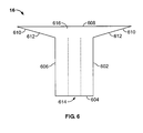
- FIG. 6 is a cross-sectional view of an exemplary embodiment of retaining clamp 16 configured to facilitate securing both pole assemblies 14 and 70 to rotor rim 18.
- each clamp 16 is substantially rectangle in shape.
- clamp 16 may have any other shape, such as, but not limited to, a square shape or a trapezoidal shape.
- each clamp 16 is shaped to match a corresponding base plate lip, bridge shoulder, and/or pole cap tapered portion.
- clamp 16 is fabricated from a non-magnetic material.
- clamp 16 is fabricated from a fiberglass/resin composite, such as, but not limited to G10 and/or G11 materials.
- clamp 16 is fabricated from a composite including, but not limited to, electrical steel and a G10 material.
- clamp 16 may be fabricated from any other suitable material that enable pole assemblies 14 and 70 to function as described herein.
- each clamp 16 includes a first sidewall 602, a second sidewall 604, a third sidewall 606, and a fourth sidewall 608.
- First and third sidewalls 602 and 606 respectively are substantially parallel to one another
- second and fourth sidewalls 604 and 608 respectively are substantially parallel to one another.
- sidewalls 602 and 606 are substantially perpendicular to sidewalls 604 and 608.
- sidewalls 602 and 606 includes a tapered portion 610 that extends from sidewalls 602 and 606 respectively towards sidewall 608.
- tapered portion 610 includes a tapered mounting surface 612.
- clamp sidewall 604 is configured to mechanically couple to rotor core 18 and clamp tapered portion 610 is configured to mechanically couple to pole cap tapered portions 36 and 38 such that pole assembly 14 is mechanically coupled to rotor 12.
- a fastener (not shown) extends through a clamp aperture 614 and into threaded inserts 616 within clamps 16. In an alternative embodiment, the fastener extends through clamp apertures 614 into to a locking fastener (not shown) positioned with rotor core 18.
- clamp sidewalls 602 and 606 are configured to mechanically couple to bridge shoulder portions 550, clamp sidewall 604 is configured to mechanically couple to base plate lip 518, and clamp tapered portion 610 is configured to mechanically couple to pole cap tapered portions 534 and 536 such that pole assembly 70 is mechanically coupled to rotor core 18.
- a fastener (not shown) extends through clamp apertures 614 through base plate lip apertures 522, and into threaded inserts 616 within clamps 16.
- the fastener extends through clamp apertures 614 through lip apertures 522, and into to a locking fastener (not shown) positioned with in rotor core 18.
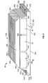
- Figure 7 is a prospective view of an exemplary embodiment of a fourth embodiment of permanent magnet pole assembly 640 and an exploded view of a second embodiment of retaining clamp 670 shown in Figure 6.
- Permanent magnet pole assembly 640 is substantially similar to pole assembly 70, (shown in Figure 5) and components of pole assembly 640 that are identical to components of pole assembly 70 are identified in Figure 7 using the same reference numerals used in Figure 5.
- Retaining clamp 670 is substantially similar to retaining clamp 16, (shown in Figure 6) and components of retaining clamp 670 that are identical to components of retaining clamp 16 are identified in Figure 7 using the same reference numerals used in Figure 6.
- pole assembly 640 includes a plurality of laminations 500 that are each sized to receive at least one permanent magnet block 42 therethrough. Moreover, laminations 500 are configured to facilitate reducing eddy current losses, facilitate minimizing cogging torque, and facilitate shielding pole assembly 640 from demagnetizing fields under abnormal conditions.
- each lamination 500 is substantially trapezoidal in shape. In alternative embodiments, laminations 500 may have any other shape, such as, but not limited to, an arcuate shape or a rectangular shape. Specifically, each lamination 500 has a contour that substantially matches a contour of stator rim (not shown).
- lamination 500 is fabricated from an electrical steel material. In alternative embodiments, laminations 500 may be fabricated from any other suitable material that enables pole assembly 640 to function as described herein.
- Each lamination 500 includes a base plate portion 502, a pole cap portion 504, and a plurality of bridge portions 506 extending therebetween such that a plurality of cavities 508 are defined therein. In the exemplary embodiment, two cavities 508 are defined therein. In alternative embodiments, each lamination 500 may have any number of cavities 508 that enables pole assembly 640 to function as described herein
- each base portion 502 includes a first sidewall 510, a second sidewall (not shown in Figure 7), a third sidewall 514, and a fourth sidewall 516.
- First and third sidewalls 510 and 514 respectively are substantially parallel to one another, and second and fourth sidewalls 516 are substantially parallel to one another.
- sidewalls 510 and 514 are substantially perpendicular to second sidewall and fourth sidewalls 516.
- at least some laminations 500 have a lip portion 518 extends radially outward from second sidewall and fourth sidewalls 516, respectively, such that a mounting surface (not shown in Figure 7) is formed.
- each pole cap portion 504 is substantially trapezoidal in shape.
- pole cap portion 504 may have any other shape, such as, but not limited to, a rectangular shape or an arcuate shape.
- each pole cap portion 504 has a contour that substantially matches a contour of stator rim (not shown).
- each pole cap portion 504 includes a first sidewall 530 and a second sidewall 532.
- First and second sidewalls 530 and 532 respectively are substantially parallel to one another.
- sidewall 532 has a first tapered portion (not shown in Figure 7) that extends from sidewall 532 towards sidewall 530 and a second tapered portion 536 that extends from sidewall 532 towards sidewall 530, respectively.
- bridge portions 506 include rectangular bridge portions 538.
- each rectangular bridge portion 538 includes a first sidewall 542, a second sidewall 544, and a body 546 extending therebetween.
- First and second sidewalls 540 and 542 respectively are substantially parallel to one another.
- Body 544 is in mechanical communication with base plate sidewall 510 and pole cap sidewall 530.
- Figure 7 also illustrates retaining clamp 670 configured to facilitate securing pole assembly 640 to rotor rim 18 (shown in Figure 1).
- each clamp 670 is substantially rectangle in shape.
- clamp 670 may have any other shape, such as, but not limited to, a square shape or a trapezoidal shape.
- each clamp 670 is shaped to match a corresponding base plate lip 518, bridge sidewall 544, and pole cap tapered portions 534 and 536.
- clamp 670 is fabricated from a non-magnetic material.
- clamp 670 is fabricated from a fiberglass/resin composite, such as, but not limited to G10 and/or G11 materials.
- clamp 670 is fabricated from a composite including, but not limited to, electrical steel and a G10 material.
- clamp 670 may be fabricated from any other suitable material that enable pole assembly 640 to function as described herein.
- each clamp 670 includes a first sidewall 602, a second sidewall 604, a third sidewall 606, and a fourth sidewall 608.
- First and third sidewalls 602 and 606 respectively are substantially parallel to one another
- second and fourth sidewalls 604 and 608 respectively are substantially parallel to one another.
- sidewalls 602 and 606 are substantially perpendicular to sidewalls 604 and 608.
- sidewall 602 includes a tapered portion 610 that extends from sidewall 602.
- tapered portion 610 includes a tapered mounting surface 612.
- clamp sidewall 604 is configured to mechanically couple to rotor core 18 (not shown in Figure 7) and clamp tapered portion 610 is configured to mechanically couple to pole cap tapered portion 536 such that pole assembly 640 is mechanically coupled to rotor 12 (not shown in Figure 7).
- a fastener (not shown) extends through a clamp aperture 614.
- the fastener extends through clamp apertures 614 into to a locking fastener (not shown) positioned with rotor core 18.
- Clamp 670 includes a fifth sidewall 616 and a sixth sidewall 618 extending between sidewalls 604 and 608.
- a recess 620 extends at least partially between sidewalls 611 and 618 respectively. Recess 620 is configured to receive and mechanically couple to base plate lip 518.
- FIG 8 is another embodiment of a retaining clamp 680 configured to facilitate securing pole assembly 640 to rotor rim 18.
- Retaining clamp 680 is substantially similar to retaining clamp 670, (shown in Figure 7) and components retaining clamp 680 that are identical to components of retaining clamp 670 are identified in Figure 8 using the same reference numerals used in Figure 7.
- each clamp 680 is substantially rectangle in shape.
- clamp 680 may have any other shape, such as, but not limited to, a square shape or a trapezoidal shape.
- each clamp 680 is shaped to match corresponding base plate lips 518, bridge sidewalls 544, and pole cap tapered portions 534 and 536.
- clamp 680 is fabricated from a non-magnetic material bonded to a laminated wedge strip 682.
- clamp 680 is fabricated from a fiberglass/resin composite, such as, but not limited to G10 and/or G11 materials bonded to laminated electrical steel.
- clamp 680 is fabricated from a composite including, but not limited to, electrical steel and a G11 material.
- clamp 680 may be fabricated from any other suitable material that enable pole assembly 640 to function as described herein.
- each clamp 680 includes a first sidewall 602, a second sidewall 604, a third sidewall 606, and a fourth sidewall 608.
- First and third sidewalls 602 and 606 respectively are substantially parallel to one another, and second and fourth sidewalls 604 and 608 respectively are substantially parallel to one another. Accordingly, sidewalls 602 and 606 are substantially perpendicular to sidewalls 604 and 608.
- sidewall 602 includes a tapered portion 610 that extends from sidewall 602.
- tapered portion 610 includes a tapered mounting surface 612.
- sidewall 604 includes an aperture 614.
- clamp 680 is coupled to laminated wedge strip 682.
- clamp sidewall 604 is configured to mechanically couple to strip 682.
- Strip 682 includes a first sidewall 684, a second sidewall 686, a third sidewall 688, and a fourth sidewall 690.
- First and third sidewalls 684 and 688 respectively are substantially parallel to one another
- second and fourth sidewalls 686 and 690 respectively are substantially parallel to one another.
- sidewalls 684 and 688 are substantially perpendicular to sidewalls 686 and 690.
- sidewall 684 tapers from sidewall 686 to sidewall 690.
- strip 682 includes an aperture 692 extending between sidewalls 686 and 690.
- clamp tapered portion 610 is configured to mechanically couple to either pole cap tapered portion 534 or 536 and strip sidewall 684 is configured to mechanically base plate lip 518 such that pole assembly 640 is mechanically coupled adjacent to rotor rim 18.
- a fastener 694 extends through a rotor aperture 696 and into strip aperture 692 and clamp aperture 614. Fastener 694 into to a locking fastener 698 positioned within sidewall 604.
- Figure 9 is side view of another embodiment of rotor 12 including permanent magnet pole assembly 760.
- Figure 10 is a detailed view of a first portion of rotor 12.
- Figure 11 is a detailed view of a second portion of rotor 12.
- PM pole assembly 760 is substantially similar to pole assembly 70, (shown in Figure 5) and components of pole assembly 760 that are identical to components of pole assembly 70 are identified in Figures 9-11 using the same reference numerals used in Figure 5.
- pole assembly 760 includes a plurality of laminations 700 and at least one permanent magnet pole 40 extending therethrough.
- laminations 700 are substantially similar to laminations 500 (shown in Figure 5) except as indicated below. Specifically, laminations 700 include base plate portion 502, pole cap portion 504, and bridge portion 506 extending therebetween such that cavity 508 is defined therein. In the exemplary embodiment, base plate portion 502 includes a full-length end 702 and a truncated end 704.
- a lip portion 706 extends from end 702 parallel to base plate portion 502 and substantially perpendicular to bridge portion 506 and a dovetail 708 extends perpendicular to base plate portion 502.
- Each lip portion 706 is adjacent another pole assembly 760 and configured to engage a clamp 800.
- Each dovetail 708 is configured to slidably couple to a rotor rim dovetail slot 710.
- End 704 includes a half dovetail 720 extending perpendicular to base plate portion 502 and configured to slidably couple to a rotor rim dovetail slot 710.
- Clamp 800 includes a half dovetail portion 802 configured to slidably couple to rotor rim dovetail slot 710, adjacent half dovetail 720 such that pole assembly 18 is slidably coupled to rotor rim 18.
- the above-described invention provides a cost-effective and reliable method for assembling pole assemblies to facilitate reducing eddy current losses.
- Positioning a permanent magnet pole between laminated base plates and laminated pole caps provides several benefits. Because the laminated base plates and pole caps are fabricated from highly permeable, high axial resistivity material, they facilitate reducing eddy current losses from the top of the pole and facilitate preventing sub-harmonic flux. Additionally, unitary laminations facilitate ease of assembly of both the pole assemblies and the rotor assemblies. Furthermore, the shape of the laminations facilitates reducing cogging torque and load ripple torque.
- pole assemblies and rotor assemblies are described above in detail.
- the pole assemblies are not limited to the specific embodiments described herein, but rather, components of each polar assembly may be utilized independently and separately from other components described herein.
- each pole assembly can also be used in combination with other rotor assemblies, and is not limited to practice with only a rotor rim as described herein. Rather, the present invention can be implemented and utilized in connection with many other rotor assemblies and electric machine configurations.
Landscapes
- Engineering & Computer Science (AREA)
- Power Engineering (AREA)
- Permanent Field Magnets Of Synchronous Machinery (AREA)
- Iron Core Of Rotating Electric Machines (AREA)
Applications Claiming Priority (1)
| Application Number | Priority Date | Filing Date | Title |
|---|---|---|---|
| US11/256,718 US7573168B2 (en) | 2005-10-24 | 2005-10-24 | Method and apparatus for assembling a permanent magnet pole assembly |
Publications (3)
| Publication Number | Publication Date |
|---|---|
| EP1777795A2 true EP1777795A2 (fr) | 2007-04-25 |
| EP1777795A3 EP1777795A3 (fr) | 2010-01-20 |
| EP1777795B1 EP1777795B1 (fr) | 2016-10-19 |
Family
ID=37726529
Family Applications (1)
| Application Number | Title | Priority Date | Filing Date |
|---|---|---|---|
| EP06253232.0A Not-in-force EP1777795B1 (fr) | 2005-10-24 | 2006-06-22 | Dispositif polaire avec aimants permanents |
Country Status (5)
| Country | Link |
|---|---|
| US (1) | US7573168B2 (fr) |
| EP (1) | EP1777795B1 (fr) |
| CN (1) | CN1956293B (fr) |
| DK (1) | DK1777795T3 (fr) |
| ES (1) | ES2603088T3 (fr) |
Cited By (27)
| Publication number | Priority date | Publication date | Assignee | Title |
|---|---|---|---|---|
| CN101860157A (zh) * | 2010-06-22 | 2010-10-13 | 哈尔滨工业大学 | 外转子永磁同步电机 |
| EP2410633A1 (fr) * | 2010-07-20 | 2012-01-25 | Siemens Aktiengesellschaft | Rotor aux aimants permanents et méthode de fabrication d'un tel rotor |
| WO2012035044A1 (fr) * | 2010-09-17 | 2012-03-22 | Höganäs Ab (Publ) | Rotor pour une machine à pôles modulée |
| EP2456048A3 (fr) * | 2010-11-18 | 2012-08-08 | General Electric Company | Structure rotorique d'une machine électromotrice à aimants permanents et insensible aux défaillances |
| EP2523316A1 (fr) * | 2011-05-11 | 2012-11-14 | Alstom Wind, S.L.U. | Rotor de générateur, procédé de fabrication et procédé d'insertion correspondant |
| EP2526608A1 (fr) * | 2010-02-16 | 2012-11-28 | Siemens Aktiengesellschaft | Procédé d'assemblage d'une partie d'un générateur, générateur et turbine d'éolienne |
| WO2011147745A3 (fr) * | 2010-05-25 | 2012-12-20 | Robert Bosch Gmbh | Composant pour une machine électrique ainsi que procédé et lamelle de tôle pour construire un tel composant |
| DE102011077554A1 (de) * | 2011-06-15 | 2012-12-20 | Siemens Aktiengesellschaft | Permanenterregte dynamoelektrische Maschine, insbesondere direkt angetriebener Windkraftgenerator |
| CN103023183A (zh) * | 2012-12-24 | 2013-04-03 | 北京金风科创风电设备有限公司 | 一种外转子永磁风力发电机 |
| WO2012171894A3 (fr) * | 2011-06-14 | 2013-07-18 | Siemens Aktiengesellschaft | Rotor pour machine à aimants permanents |
| EP2645535A1 (fr) * | 2012-03-30 | 2013-10-02 | Alstom Wind, S.L.U. | Rotor à aimant permanent |
| EP2658090A1 (fr) * | 2012-04-26 | 2013-10-30 | Siemens Aktiengesellschaft | Ensemble d'engagement d'aimant de rotor |
| EP2713478A1 (fr) * | 2012-09-27 | 2014-04-02 | Siemens Aktiengesellschaft | Structure externe de générateur |
| JP2016513946A (ja) * | 2013-03-08 | 2016-05-16 | マグノマティックス リミテッドMagnomatics Limited | 磁石保持装置及び方法 |
| RU2641896C2 (ru) * | 2013-02-20 | 2018-01-23 | Лор Электромеканик | Несущая магниты подвижная часть для синхронной машины с постоянными магнитами |
| EP3402046A1 (fr) * | 2017-05-10 | 2018-11-14 | GE Renewable Technologies Wind B.V. | Modules à aimants permanents |
| CN111200323A (zh) * | 2018-11-20 | 2020-05-26 | 日本电产株式会社 | 转子以及马达 |
| EP3618235A4 (fr) * | 2018-07-04 | 2020-07-29 | Beijing Goldwind Science & Creation Windpower Equipment Co., Ltd. | Rotor, procédé de montage de module de pôles monobloc pour rotor, procédé de remplacement de module de pôles monobloc pour rotor, et moteur |
| CN112054605A (zh) * | 2019-06-06 | 2020-12-08 | 西门子歌美飒可再生能源公司 | 用于永磁电机的永磁体模块 |
| EP3748813A1 (fr) * | 2019-06-06 | 2020-12-09 | Siemens Gamesa Renewable Energy A/S | Module d'aimant permanent pour machine à aimant permanent |
| DE102019117691A1 (de) * | 2019-07-01 | 2021-01-07 | Dr. Ing. H.C. F. Porsche Aktiengesellschaft | Verfahren zum Herstellen eines Rotors einer elektrischen Maschine und Rotor einer elektrischen Maschine |
| WO2022034319A1 (fr) * | 2020-08-14 | 2022-02-17 | Safran Electrical & Power | Rotor pour machine électrique à aimant permanent |
| EP3961865A4 (fr) * | 2019-05-23 | 2022-06-15 | Beijing Goldwind Science & Creation Windpower Equipment Co. Ltd. | Procédé d'assemblage de moteur de grand diamètre |
| EP4037148A1 (fr) * | 2021-01-28 | 2022-08-03 | Siemens Gamesa Renewable Energy A/S | Module d'aimant permanent pour machine à aimant permanent |
| EP3567701B1 (fr) * | 2018-05-09 | 2023-02-01 | Siemens Gamesa Renewable Energy A/S | Module d'aimant pour machine à aimant permanent |
| US11661646B2 (en) | 2021-04-21 | 2023-05-30 | General Electric Comapny | Dual phase magnetic material component and method of its formation |
| US11926880B2 (en) | 2021-04-21 | 2024-03-12 | General Electric Company | Fabrication method for a component having magnetic and non-magnetic dual phases |
Families Citing this family (27)
| Publication number | Priority date | Publication date | Assignee | Title |
|---|---|---|---|---|
| DE102006048966A1 (de) * | 2006-10-17 | 2008-04-30 | Siemens Ag | Magnetmodul für eine permanentmagneterregte elektrische Maschine |
| US7710081B2 (en) | 2006-10-27 | 2010-05-04 | Direct Drive Systems, Inc. | Electromechanical energy conversion systems |
| US7781932B2 (en) * | 2007-12-31 | 2010-08-24 | General Electric Company | Permanent magnet assembly and method of manufacturing same |
| US8253298B2 (en) * | 2008-07-28 | 2012-08-28 | Direct Drive Systems, Inc. | Slot configuration of an electric machine |
| FI121614B (fi) * | 2008-12-17 | 2011-01-31 | Switch Drive Systems Oy | Kestomagneettimoduuli sähkökonetta varten |
| DE102008063045A1 (de) * | 2008-12-23 | 2010-07-01 | Aerodyn Energiesysteme Gmbh | Synchronmaschine |
| DE102009006017A1 (de) * | 2009-01-23 | 2010-08-05 | Avantis Ltd. | Magnetrad |
| DE102009005956A1 (de) * | 2009-01-23 | 2010-07-29 | Avantis Ltd. | Magnetring |
| US7851935B2 (en) * | 2009-08-11 | 2010-12-14 | Jason Tsao | Solar and wind energy converter |
| US8664819B2 (en) * | 2009-08-18 | 2014-03-04 | Northern Power Systems Utility Scale, Inc. | Method and apparatus for permanent magnet attachment in an electromechanical machine |
| US9515529B2 (en) | 2009-08-18 | 2016-12-06 | Northern Power Systems, Inc. | Method and apparatus for permanent magnet attachment in an electromechanical machine |
| JP2011120328A (ja) * | 2009-12-01 | 2011-06-16 | Yaskawa Electric Corp | 永久磁石形モータ用のロータ、永久磁石形モータ及びこれらの製造方法 |
| US10137542B2 (en) | 2010-01-14 | 2018-11-27 | Senvion Gmbh | Wind turbine rotor blade components and machine for making same |
| CN102762850B (zh) | 2010-01-14 | 2015-04-08 | 耐普迪考股份有限公司 | 风力涡轮机转子叶片部件及其制造方法 |
| EP2348619B1 (fr) * | 2010-01-20 | 2014-09-17 | Siemens Aktiengesellschaft | Ensemble d'aimants |
| US8575871B1 (en) | 2010-07-23 | 2013-11-05 | Christopher Moore | Modular component electric machine |
| FI124814B (fi) * | 2010-10-18 | 2015-01-30 | Lappeenrannan Teknillinen Yliopisto | Sähkökoneen staattori ja sähkökone |
| CN103999330B (zh) | 2011-11-30 | 2017-03-29 | Abb研究有限公司 | 电机和电机转子 |
| CN102420479B (zh) * | 2011-12-16 | 2013-04-24 | 铜陵浩岩节能科技有限公司 | 一种永磁同步电机的转子 |
| CN103779984A (zh) * | 2012-10-23 | 2014-05-07 | 德昌电机(深圳)有限公司 | 电机 |
| JP2015027161A (ja) * | 2013-07-25 | 2015-02-05 | 株式会社東芝 | 回転電機 |
| EP2947752A1 (fr) | 2014-05-19 | 2015-11-25 | ALSTOM Renewable Technologies | Mécanisme de calage |
| US9673667B2 (en) | 2014-07-22 | 2017-06-06 | General Electric Company | System and method for preventing stator permanent magnet demagnetization during vacuum pressure impregnation |
| JP6436114B2 (ja) * | 2016-02-19 | 2018-12-12 | 株式会社豊田自動織機 | 永久磁石式回転電機 |
| CN107070033B (zh) * | 2017-05-08 | 2019-05-07 | 北京金风科创风电设备有限公司 | 转子及其制造方法 |
| DE102018105249A1 (de) * | 2018-03-07 | 2019-09-12 | Nidec Corporation | Rotoreinheit und Elektromotor |
| CN110808650B (zh) * | 2019-11-12 | 2020-09-01 | 中车株洲电机有限公司 | 一种永磁体固定结构 |
Family Cites Families (32)
| Publication number | Priority date | Publication date | Assignee | Title |
|---|---|---|---|---|
| US1976230A (en) * | 1930-12-25 | 1934-10-09 | Mitsubishi Electric Corp | Permanent magnet and method of manufacturing same |
| US2485474A (en) * | 1947-01-11 | 1949-10-18 | Keefe And Merritt Company O | Permanent magnet rotor |
| US4126933A (en) * | 1977-07-14 | 1978-11-28 | Carrier Corporation | Method for assembling a permanent magnet rotor |
| US4139790A (en) * | 1977-08-31 | 1979-02-13 | Reliance Electric Company | Direct axis aiding permanent magnets for a laminated synchronous motor rotor |
| US4393320A (en) * | 1981-09-02 | 1983-07-12 | Carrier Corporation | Permanent magnet rotor |
| US4510680A (en) * | 1982-12-27 | 1985-04-16 | General Electric Company | Method of making a permanent magnet rotor |
| US4525925A (en) * | 1983-09-22 | 1985-07-02 | General Electric Company | Method of making permanent magnet rotor |
| US4506181A (en) * | 1984-03-02 | 1985-03-19 | General Electric Company | Permanent magnet rotor with complete amortisseur |
| US4795936A (en) * | 1986-08-26 | 1989-01-03 | Midwest Dynamometer & Engineering Co. | Driven rotary shaft system using permanent magnets |
| US4769624A (en) * | 1986-10-30 | 1988-09-06 | General Motors Corporation | Permanent magnet assembly |
| US4916346A (en) * | 1987-12-28 | 1990-04-10 | General Electric Company | Composite rotor lamination for use in reluctance hompolar, and permanent magnet machines |
| US4918831A (en) * | 1987-12-28 | 1990-04-24 | General Electric Company | Method of fabricating composite rotor laminations for use in reluctance, homopolar and permanent magnet machines |
| JPH0757076B2 (ja) * | 1988-05-30 | 1995-06-14 | 三菱電機株式会社 | 回転電機の回転子 |
| WO1994005073A2 (fr) * | 1992-08-21 | 1994-03-03 | Fisher & Paykel Limited | Moteur de ventilateur electrique |
| JPH0833247A (ja) * | 1994-07-12 | 1996-02-02 | Nabco Ltd | 磁石部材の回転体への取付け方法および渦電流式リターダ |
| US5691589A (en) * | 1995-06-30 | 1997-11-25 | Kaman Electromagnetics Corporation | Detachable magnet carrier for permanent magnet motor |
| US5894183A (en) * | 1996-10-29 | 1999-04-13 | Caterpillar Inc. | Permanent magnet generator rotor |
| US5952755A (en) * | 1997-03-18 | 1999-09-14 | Electric Boat Corporation | Permanent magnet motor rotor |
| JPH10336929A (ja) * | 1997-05-28 | 1998-12-18 | Mitsubishi Electric Corp | 回転磁石電動機のロータ及びその製造方法 |
| JP3451396B2 (ja) * | 1999-01-07 | 2003-09-29 | ミネベア株式会社 | ステッピングモータ |
| US6509664B2 (en) * | 2000-01-13 | 2003-01-21 | General Electric Company | Hybrid synchronous machines comprising permanent magnets and excitation windings in cylindrical element slots |
| US6441522B1 (en) * | 2000-03-31 | 2002-08-27 | Coleman Powermate, Inc. | Electromagnetic apparatus employing high permeability low conductivity element |
| DE10215251A1 (de) * | 2002-04-06 | 2003-10-16 | Bosch Gmbh Robert | Elektrische Maschine, insbesondere Permanentmagnet erregte Motore |
| FR2839211A1 (fr) * | 2002-04-29 | 2003-10-31 | Conception & Dev Michelin Sa | Machine electrique dont le rotor est specialement adapte aux hautes vitesses |
| NZ537718A (en) * | 2002-06-20 | 2008-10-31 | Toshiba Kk | Rotor for permanent magnet motor of outer rotor type |
| DK200201771A (da) | 2002-11-15 | 2004-05-16 | Bonus Energy As | Rotor samt fremgangsmåde til montering af magneter i en rotor |
| JP4280542B2 (ja) * | 2003-04-30 | 2009-06-17 | 日本電産コパル株式会社 | ステッピングモータ |
| US6984908B2 (en) * | 2003-08-26 | 2006-01-10 | Deere & Company | Permanent magnet motor |
| US7154193B2 (en) * | 2004-09-27 | 2006-12-26 | General Electric Company | Electrical machine with double-sided stator |
| US7154191B2 (en) * | 2004-06-30 | 2006-12-26 | General Electric Company | Electrical machine with double-sided rotor |
| US7154192B2 (en) * | 2004-09-27 | 2006-12-26 | General Electric Company | Electrical machine with double-sided lamination stack |
| US7692357B2 (en) * | 2004-12-16 | 2010-04-06 | General Electric Company | Electrical machines and assemblies including a yokeless stator with modular lamination stacks |
-
2005
- 2005-10-24 US US11/256,718 patent/US7573168B2/en not_active Expired - Fee Related
-
2006
- 2006-06-22 EP EP06253232.0A patent/EP1777795B1/fr not_active Not-in-force
- 2006-06-22 DK DK06253232.0T patent/DK1777795T3/en active
- 2006-06-22 ES ES06253232.0T patent/ES2603088T3/es active Active
- 2006-06-23 CN CN200610107679XA patent/CN1956293B/zh not_active Expired - Fee Related
Cited By (45)
| Publication number | Priority date | Publication date | Assignee | Title |
|---|---|---|---|---|
| EP2526608A1 (fr) * | 2010-02-16 | 2012-11-28 | Siemens Aktiengesellschaft | Procédé d'assemblage d'une partie d'un générateur, générateur et turbine d'éolienne |
| WO2011147745A3 (fr) * | 2010-05-25 | 2012-12-20 | Robert Bosch Gmbh | Composant pour une machine électrique ainsi que procédé et lamelle de tôle pour construire un tel composant |
| CN101860157A (zh) * | 2010-06-22 | 2010-10-13 | 哈尔滨工业大学 | 外转子永磁同步电机 |
| EP2410633A1 (fr) * | 2010-07-20 | 2012-01-25 | Siemens Aktiengesellschaft | Rotor aux aimants permanents et méthode de fabrication d'un tel rotor |
| US8629595B2 (en) | 2010-07-20 | 2014-01-14 | Siemens Aktiengesellschaft | Permanent magnet rotor arrangement and method for producing such an arrangement |
| WO2012035044A1 (fr) * | 2010-09-17 | 2012-03-22 | Höganäs Ab (Publ) | Rotor pour une machine à pôles modulée |
| AU2011303910A8 (en) * | 2010-09-17 | 2015-11-12 | Hoganas Ab (Publ) | Rotor for modulated pole machine |
| RU2568300C2 (ru) * | 2010-09-17 | 2015-11-20 | Хеганес Аб (Пабл) | Ротор для электрической машины с модуляцией полюсов |
| AU2011303910B2 (en) * | 2010-09-17 | 2015-07-23 | Hoganas Ab (Publ) | Rotor for modulated pole machine |
| EP2456048A3 (fr) * | 2010-11-18 | 2012-08-08 | General Electric Company | Structure rotorique d'une machine électromotrice à aimants permanents et insensible aux défaillances |
| US9973045B2 (en) | 2011-05-11 | 2018-05-15 | Ge Renewable Technologies Wind B.V. | Generator rotor, assembly method and related insertion tool |
| US10958118B2 (en) | 2011-05-11 | 2021-03-23 | Ge Renewable Technologies Wind, B.V. | Method of assembling a generator rotor of a generator |
| WO2012152878A1 (fr) * | 2011-05-11 | 2012-11-15 | Alstom Wind, S.L.U. | Rotor de génératrice, procédé d'assemblage et outil d'insertion correspondant |
| EP2523316A1 (fr) * | 2011-05-11 | 2012-11-14 | Alstom Wind, S.L.U. | Rotor de générateur, procédé de fabrication et procédé d'insertion correspondant |
| WO2012171894A3 (fr) * | 2011-06-14 | 2013-07-18 | Siemens Aktiengesellschaft | Rotor pour machine à aimants permanents |
| DE102011077554A1 (de) * | 2011-06-15 | 2012-12-20 | Siemens Aktiengesellschaft | Permanenterregte dynamoelektrische Maschine, insbesondere direkt angetriebener Windkraftgenerator |
| EP2645535A1 (fr) * | 2012-03-30 | 2013-10-02 | Alstom Wind, S.L.U. | Rotor à aimant permanent |
| WO2013144284A3 (fr) * | 2012-03-30 | 2014-01-16 | Alstom Renovables España, S.L. | Rotor à aimant permanent |
| EP2658090A1 (fr) * | 2012-04-26 | 2013-10-30 | Siemens Aktiengesellschaft | Ensemble d'engagement d'aimant de rotor |
| EP2713478A1 (fr) * | 2012-09-27 | 2014-04-02 | Siemens Aktiengesellschaft | Structure externe de générateur |
| WO2014048789A3 (fr) * | 2012-09-27 | 2015-01-29 | Siemens Aktiengesellschaft | Structure extérieure d'une génératrice |
| CN103023183A (zh) * | 2012-12-24 | 2013-04-03 | 北京金风科创风电设备有限公司 | 一种外转子永磁风力发电机 |
| RU2641896C2 (ru) * | 2013-02-20 | 2018-01-23 | Лор Электромеканик | Несущая магниты подвижная часть для синхронной машины с постоянными магнитами |
| JP2016513946A (ja) * | 2013-03-08 | 2016-05-16 | マグノマティックス リミテッドMagnomatics Limited | 磁石保持装置及び方法 |
| EP3402046A1 (fr) * | 2017-05-10 | 2018-11-14 | GE Renewable Technologies Wind B.V. | Modules à aimants permanents |
| EP3567701B1 (fr) * | 2018-05-09 | 2023-02-01 | Siemens Gamesa Renewable Energy A/S | Module d'aimant pour machine à aimant permanent |
| EP3618235A4 (fr) * | 2018-07-04 | 2020-07-29 | Beijing Goldwind Science & Creation Windpower Equipment Co., Ltd. | Rotor, procédé de montage de module de pôles monobloc pour rotor, procédé de remplacement de module de pôles monobloc pour rotor, et moteur |
| AU2019216612B2 (en) * | 2018-07-04 | 2020-09-17 | Beijing Goldwind Science & Creation Windpower Equipment Co., Ltd. | Rotor, assembly method and replacement method for integrated magnetic pole modules of rotor, and generator |
| US11349376B2 (en) | 2018-07-04 | 2022-05-31 | Beijing Goldwind Science & Creation Windpower Equipment Co., Ltd. | Rotor, assembly method and replacement method for integrated magnetic pole modules of rotor, and generator |
| CN111200323B (zh) * | 2018-11-20 | 2022-10-25 | 日本电产株式会社 | 转子以及马达 |
| CN111200323A (zh) * | 2018-11-20 | 2020-05-26 | 日本电产株式会社 | 转子以及马达 |
| US12206299B2 (en) | 2019-05-23 | 2025-01-21 | Beijing Goldwind Science & Creation Windpower Equipment Co., Ltd. | Method for assembling large-diameter electric motor |
| EP3961865A4 (fr) * | 2019-05-23 | 2022-06-15 | Beijing Goldwind Science & Creation Windpower Equipment Co. Ltd. | Procédé d'assemblage de moteur de grand diamètre |
| CN112054605A (zh) * | 2019-06-06 | 2020-12-08 | 西门子歌美飒可再生能源公司 | 用于永磁电机的永磁体模块 |
| CN112054605B (zh) * | 2019-06-06 | 2025-08-19 | 西门子歌美飒可再生能源公司 | 用于永磁电机的永磁体模块 |
| EP3748813A1 (fr) * | 2019-06-06 | 2020-12-09 | Siemens Gamesa Renewable Energy A/S | Module d'aimant permanent pour machine à aimant permanent |
| DE102019117691B4 (de) * | 2019-07-01 | 2025-07-03 | Dr. Ing. H.C. F. Porsche Aktiengesellschaft | Verfahren zum Herstellen eines Rotors einer elektrischen Maschine und Rotor einer elektrischen Maschine |
| DE102019117691A1 (de) * | 2019-07-01 | 2021-01-07 | Dr. Ing. H.C. F. Porsche Aktiengesellschaft | Verfahren zum Herstellen eines Rotors einer elektrischen Maschine und Rotor einer elektrischen Maschine |
| WO2022034319A1 (fr) * | 2020-08-14 | 2022-02-17 | Safran Electrical & Power | Rotor pour machine électrique à aimant permanent |
| GB2598103B (en) * | 2020-08-14 | 2025-08-06 | Safran Electrical & Power | Rotor for a permanent magnet electrical machine |
| GB2598103A (en) * | 2020-08-14 | 2022-02-23 | Safran Electrical & Power | Rotor for a permanent magnet electrical machine |
| EP4037148A1 (fr) * | 2021-01-28 | 2022-08-03 | Siemens Gamesa Renewable Energy A/S | Module d'aimant permanent pour machine à aimant permanent |
| US11926880B2 (en) | 2021-04-21 | 2024-03-12 | General Electric Company | Fabrication method for a component having magnetic and non-magnetic dual phases |
| US11976367B2 (en) | 2021-04-21 | 2024-05-07 | General Electric Company | Dual phase magnetic material component and method of its formation |
| US11661646B2 (en) | 2021-04-21 | 2023-05-30 | General Electric Comapny | Dual phase magnetic material component and method of its formation |
Also Published As
| Publication number | Publication date |
|---|---|
| DK1777795T3 (en) | 2016-12-12 |
| ES2603088T3 (es) | 2017-02-23 |
| EP1777795A3 (fr) | 2010-01-20 |
| EP1777795B1 (fr) | 2016-10-19 |
| CN1956293B (zh) | 2011-11-16 |
| CN1956293A (zh) | 2007-05-02 |
| US7573168B2 (en) | 2009-08-11 |
| US20070090711A1 (en) | 2007-04-26 |
Similar Documents
| Publication | Publication Date | Title |
|---|---|---|
| US7573168B2 (en) | Method and apparatus for assembling a permanent magnet pole assembly | |
| JP6638202B2 (ja) | アキシャルギャップ型の回転電機 | |
| CN100536288C (zh) | 永久磁铁同步电动机 | |
| EP2485368A1 (fr) | Machine rotative du type lundell | |
| CA1211148A (fr) | Rotor a aimant permanent et amortissement absolu | |
| US7233090B2 (en) | Electric machine, in particular brushless synchronous motor | |
| US7228616B2 (en) | System and method for magnetization of permanent magnet rotors in electrical machines | |
| CN108370178B (zh) | 轴向间隙型旋转电机及其制造方法 | |
| JP6464856B2 (ja) | アキシャルギャップ型の回転電機 | |
| EP0678967A1 (fr) | Rotor pour moteur à aimants permanents | |
| CN111527670A (zh) | 旋转电机 | |
| CN101630887B (zh) | 永久磁铁同步电动机 | |
| KR20150016906A (ko) | 토크 리플을 감소시킨 스포크 영구 자석 머신 및 그 제조 방법 | |
| CN111566904B (zh) | 旋转电机 | |
| US20160344242A1 (en) | Variable magnetic flux motor having rotor in which two different kinds of magnets are embedded | |
| US20130187485A1 (en) | Rotaring electrical machine | |
| CN111542991A (zh) | 旋转电机 | |
| EP1298773A1 (fr) | Moteur synchrone a aimant permanent | |
| JP2016178834A (ja) | 回転電機 | |
| JP6394451B2 (ja) | アキシャルギャップ型の回転電機 | |
| US20140152137A1 (en) | Motor with variable magnet flux | |
| JP2017093147A (ja) | 回転電機 | |
| US20200119604A1 (en) | Rotary electric machine | |
| US10720807B2 (en) | Magnet-type rotor, rotary electric machine equipped with magnet-type rotor, and electric vehicle equipped with rotary electric machine | |
| US20090026876A1 (en) | Hybrid construction electric machine |
Legal Events
| Date | Code | Title | Description |
|---|---|---|---|
| PUAI | Public reference made under article 153(3) epc to a published international application that has entered the european phase |
Free format text: ORIGINAL CODE: 0009012 |
|
| AK | Designated contracting states |
Kind code of ref document: A2 Designated state(s): AT BE BG CH CY CZ DE DK EE ES FI FR GB GR HU IE IS IT LI LT LU LV MC NL PL PT RO SE SI SK TR |
|
| AX | Request for extension of the european patent |
Extension state: AL BA HR MK YU |
|
| RAP1 | Party data changed (applicant data changed or rights of an application transferred) |
Owner name: GENERAL ELECTRIC COMPANY |
|
| PUAL | Search report despatched |
Free format text: ORIGINAL CODE: 0009013 |
|
| AK | Designated contracting states |
Kind code of ref document: A3 Designated state(s): AT BE BG CH CY CZ DE DK EE ES FI FR GB GR HU IE IS IT LI LT LU LV MC NL PL PT RO SE SI SK TR |
|
| AX | Request for extension of the european patent |
Extension state: AL BA HR MK RS |
|
| 17P | Request for examination filed |
Effective date: 20100720 |
|
| 17Q | First examination report despatched |
Effective date: 20100813 |
|
| AKX | Designation fees paid |
Designated state(s): DE DK ES FR |
|
| GRAP | Despatch of communication of intention to grant a patent |
Free format text: ORIGINAL CODE: EPIDOSNIGR1 |
|
| INTG | Intention to grant announced |
Effective date: 20160718 |
|
| GRAS | Grant fee paid |
Free format text: ORIGINAL CODE: EPIDOSNIGR3 |
|
| GRAA | (expected) grant |
Free format text: ORIGINAL CODE: 0009210 |
|
| AK | Designated contracting states |
Kind code of ref document: B1 Designated state(s): DE DK ES FR |
|
| REG | Reference to a national code |
Ref country code: DE Ref legal event code: R096 Ref document number: 602006050600 Country of ref document: DE |
|
| REG | Reference to a national code |
Ref country code: DK Ref legal event code: T3 Effective date: 20161206 |
|
| REG | Reference to a national code |
Ref country code: ES Ref legal event code: FG2A Ref document number: 2603088 Country of ref document: ES Kind code of ref document: T3 Effective date: 20170223 |
|
| REG | Reference to a national code |
Ref country code: FR Ref legal event code: PLFP Year of fee payment: 12 |
|
| REG | Reference to a national code |
Ref country code: DE Ref legal event code: R097 Ref document number: 602006050600 Country of ref document: DE |
|
| PGFP | Annual fee paid to national office [announced via postgrant information from national office to epo] |
Ref country code: FR Payment date: 20170627 Year of fee payment: 12 Ref country code: DK Payment date: 20170626 Year of fee payment: 12 |
|
| PLBE | No opposition filed within time limit |
Free format text: ORIGINAL CODE: 0009261 |
|
| STAA | Information on the status of an ep patent application or granted ep patent |
Free format text: STATUS: NO OPPOSITION FILED WITHIN TIME LIMIT |
|
| 26N | No opposition filed |
Effective date: 20170720 |
|
| PGFP | Annual fee paid to national office [announced via postgrant information from national office to epo] |
Ref country code: DE Payment date: 20170628 Year of fee payment: 12 Ref country code: ES Payment date: 20170705 Year of fee payment: 12 |
|
| REG | Reference to a national code |
Ref country code: DE Ref legal event code: R119 Ref document number: 602006050600 Country of ref document: DE |
|
| REG | Reference to a national code |
Ref country code: DK Ref legal event code: EBP Effective date: 20180630 |
|
| PG25 | Lapsed in a contracting state [announced via postgrant information from national office to epo] |
Ref country code: FR Free format text: LAPSE BECAUSE OF NON-PAYMENT OF DUE FEES Effective date: 20180630 Ref country code: DE Free format text: LAPSE BECAUSE OF NON-PAYMENT OF DUE FEES Effective date: 20190101 |
|
| PG25 | Lapsed in a contracting state [announced via postgrant information from national office to epo] |
Ref country code: DK Free format text: LAPSE BECAUSE OF NON-PAYMENT OF DUE FEES Effective date: 20180630 |
|
| REG | Reference to a national code |
Ref country code: ES Ref legal event code: FD2A Effective date: 20190916 |
|
| PG25 | Lapsed in a contracting state [announced via postgrant information from national office to epo] |
Ref country code: ES Free format text: LAPSE BECAUSE OF NON-PAYMENT OF DUE FEES Effective date: 20180623 |