EP1780118A2 - Dispositif pour contrôler et mesurer le jeu entre la mèche de gouvernail d'un bateau et son palier - Google Patents
Dispositif pour contrôler et mesurer le jeu entre la mèche de gouvernail d'un bateau et son palier Download PDFInfo
- Publication number
- EP1780118A2 EP1780118A2 EP06016683A EP06016683A EP1780118A2 EP 1780118 A2 EP1780118 A2 EP 1780118A2 EP 06016683 A EP06016683 A EP 06016683A EP 06016683 A EP06016683 A EP 06016683A EP 1780118 A2 EP1780118 A2 EP 1780118A2
- Authority
- EP
- European Patent Office
- Prior art keywords
- measuring
- guide rail
- rail
- rudder
- probe
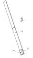
- Prior art date
- Legal status (The legal status is an assumption and is not a legal conclusion. Google has not performed a legal analysis and makes no representation as to the accuracy of the status listed.)
- Granted
Links
- 239000000523 sample Substances 0.000 claims abstract description 70
- 238000005259 measurement Methods 0.000 claims abstract description 15
- 239000000463 material Substances 0.000 claims description 16
- 239000013013 elastic material Substances 0.000 claims description 3
- 238000000034 method Methods 0.000 claims description 2
- XLYOFNOQVPJJNP-UHFFFAOYSA-N water Substances O XLYOFNOQVPJJNP-UHFFFAOYSA-N 0.000 description 3
- 238000003780 insertion Methods 0.000 description 2
- 230000037431 insertion Effects 0.000 description 2
- 230000001419 dependent effect Effects 0.000 description 1
- 238000007689 inspection Methods 0.000 description 1
- 239000002184 metal Substances 0.000 description 1
- 238000000465 moulding Methods 0.000 description 1
Images





Classifications
-
- G—PHYSICS
- G01—MEASURING; TESTING
- G01B—MEASURING LENGTH, THICKNESS OR SIMILAR LINEAR DIMENSIONS; MEASURING ANGLES; MEASURING AREAS; MEASURING IRREGULARITIES OF SURFACES OR CONTOURS
- G01B5/00—Measuring arrangements characterised by the use of mechanical techniques
- G01B5/14—Measuring arrangements characterised by the use of mechanical techniques for measuring distance or clearance between spaced objects or spaced apertures
- G01B5/146—Measuring arrangements characterised by the use of mechanical techniques for measuring distance or clearance between spaced objects or spaced apertures measuring play on bearings
-
- B—PERFORMING OPERATIONS; TRANSPORTING
- B63—SHIPS OR OTHER WATERBORNE VESSELS; RELATED EQUIPMENT
- B63B—SHIPS OR OTHER WATERBORNE VESSELS; EQUIPMENT FOR SHIPPING
- B63B3/00—Hulls characterised by their structure or component parts
- B63B3/14—Hull parts
- B63B3/40—Stern posts; Stern frames
-
- B—PERFORMING OPERATIONS; TRANSPORTING
- B63—SHIPS OR OTHER WATERBORNE VESSELS; RELATED EQUIPMENT
- B63H—MARINE PROPULSION OR STEERING
- B63H25/00—Steering; Slowing-down otherwise than by use of propulsive elements; Dynamic anchoring, i.e. positioning vessels by means of main or auxiliary propulsive elements
- B63H25/06—Steering by rudders
- B63H25/38—Rudders
-
- B—PERFORMING OPERATIONS; TRANSPORTING
- B63—SHIPS OR OTHER WATERBORNE VESSELS; RELATED EQUIPMENT
- B63H—MARINE PROPULSION OR STEERING
- B63H25/00—Steering; Slowing-down otherwise than by use of propulsive elements; Dynamic anchoring, i.e. positioning vessels by means of main or auxiliary propulsive elements
- B63H25/52—Parts for steering not otherwise provided for
Definitions
- the invention relates to a device for controlling and measuring the neck bearing play of the rudder stock of a rudder for watercraft according to the preamble of claim 1.
- the game in the neck storage area between the rudder of a rowing boat and the rudder box is subject to constant controls, the rudder stock is subjected to pivotal movements about its longitudinal axis, in which case the remaining game is measured.
- These game control measurements are made on ships in dock. An underwater inspection by divers with ships in the water is not possible.
- Object of the present invention is to provide a device for controlling and measuring the neck bearing game in rowing of watercraft, which can be used underwater, so that divers can make the control and the measurement of the game, whereby the possibility is given to the game control any time to make.
- a generic device by means of a, provided with a handle-like handle rail in the gap between the outer bearing and the inner bearing into the Sp fauxmess Society insertable measuring rail of a resilient-elastic and having inherent rigidity material with arranged at the free end probe for game width measurement, characterized in that the measuring rail are exchanged with the measuring probe with predetermined strength against measuring rails with probes with different strengths in order to achieve a match of the game width with the strength of a measuring rail with the probe.
- the handling of the device is simple.
- the measuring rail displaceably mounted on the guide rail with the measuring probe arranged at its free end is pushed in so far through an opening in the wall of the rudder blade of the rudder that the angled end of the guide rail comes to lie in the interior of the rudder blade.
- the measuring rail which preferably has twice the length of the guide rail, is inserted into the gap between the two bearings of the rudder stock and the rudder coker until the measuring probe comes to rest at the end of the measuring rail in the play measuring range.
- the game has a greater width compared to the total thickness of the measuring rail and the probe, so long as measuring rails with probes with other total strengths introduced until the play width of the total thickness of the inserted measuring rail with the probe corresponds, so that by the measuring rails and their probes predetermined values the width of the game can be accurately sized. For these measurements, a number of measuring rails are available with their probes with different strengths.
- the invention provides a device which provided with a handle-like handle guide rail with at the free end arcuately angled guide rail portion and displaceable on the guide rail and deflected in the angled guide rail portion and in the gap between the outer bearing and the bottom bracket up to the play measuring range insertable measuring rail of a resilient-elastic and an inherent rigidity having measuring rail arranged at the free end measuring probe for the game width measurement.
- the measuring rail is made of a resilient-elastic material and still has a corresponding inherent rigidity, so that the guided on the guide rail measuring rail can be deflected arcuate in the bent guide rail section, so that the measuring rail can be moved from the horizontal to a vertical position, wherein in the end position of the measuring rail it is still held by the guide rail.
- the further embodiment of the device provides that the guide rail with the one-sided formed handle-like handle and formed at the other end arcuately formed at an angle of preferably 45 ° guide rail portion, wherein the guide rail a number of bow-like brackets and one on the inner wall side of the Having deflected guide rail section arranged deflection roller, so that for the guidance of the measuring rail on the Guide rail the measuring rail is held by the bracket-like brackets on the guide rail.
- the measuring rail is guided between the deflection roller and the bent guide rail end section and bent approximately 45 °, so that the end of the measuring rail can be introduced with the measuring probe into the gap between the rudder shaft and the rudder trunk in the neck bearing area.
- the measuring rail is guided in the bent guide rail section between this and the deflection roller such that the measuring rail is led out at about a right angle from the end of the bent guide rail section, wherein the measuring rail carries at its free end of the bent measuring rail section, the measuring probe, which consists of a plate-shaped body exists whose strength plus the material thickness of the guide rail is a measure of the width of the neck bearing game.
- the measuring rail held and guided on the guide rail with the measuring probe having a predetermined thickness can be exchanged for measuring rails with measuring probes of other strengths.
- the measuring rail In order to introduce the measuring rail into the gap for clearance measurement, the measuring rail has a length which is greater than the length of the guide rail. Both the measuring rail and the measuring probe are preferably made of plastic or another suitable material.
- the guide rail consists of a rigid, rigid and rigid material.
- the measuring probe on the measuring rail is fixedly or detachably connected to it, so that in the latter embodiment, the measuring probes to the Measuring rails can be exchanged for measuring probes of other strength.
- the invention provides a method for performing checks and measuring the neck bearing play between the outer bearing on the rudder stock of a rudder for watercraft and the outer bearing corresponding bottom bracket on the rudder trunk using the device described above, in which the guide rail with attached measuring rail with its bent end portion is pushed so far into an opening in the outer wall of the rudder blade of the rudder that the bent guide rail end portion of the guide rail in the lower region of the gap between the outer bearing on the rudder shaft of the rudder for watercraft and the inner bearing on the rudder trunk comes to rest, whereupon the measuring rail the guide rail is inserted into the gap so far that the measuring probe of the measuring rail comes to rest in the play measuring range, whereby measuring rails with measuring probes against measuring rails with measuring probes of different thickness are placed on the guide Replaced until the strength of the measuring rail together with the strength of the probe corresponds to the width of the game.
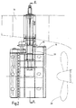
- 10 denotes a hull, 15 a rudder blade of a rudder, 20 a rudder trunk and 25 a rudder stock.
- Trained as a cantilever rudder trunk 20 is fixedly connected at its upper end 20a with the indicated at 10 hull and has a central inner bore 21 which extends in the rudder trunk longitudinal direction and which receives the rudder shaft 25.
- the rudder trunk 20 is guided into the rudder blade 15, which is fixedly connected to the free lower end of the guided through the inner bore 21 of the rudder coker 20 Rudder shaft 25.
- the rudder blade 15 of the rudder is assigned a propeller 28 (FIGS. 1 and 2). As shown in FIG. 14, at least one opening 17 is provided in the outer wall 16 of the rudder blade 15.
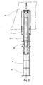
- a bearing 30 is provided in the lower portion of the rudder stock 25, which is formed by a arranged on the rudder stock 25 outer bearing and a disposed on the inner wall side of the rudder coker 20 bottom bracket 32, wherein the bottom bracket 32 as a sleeve is fixedly arranged in the rudder trunk 20 (FIGS. 5, 6 and 7).
- a gap 35 is formed, in which the device 100 designed according to the invention can be introduced in order to be able to control and measure the play between the rudder shaft 25 and the rudder trunk 20.
- the play measuring range is indicated in Fig. 7 at 40 and the neck bearing game at 50.
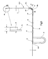
- the device 100 for controlling and measuring the neck bearing play 50 between the outer bearing 31 on the rudder stock 25 and on the corresponding with the outer bearing 31 bottom bracket 32 on the rudder trunk 20 is shown in FIG. 8, 9, 10, 11 and 12 of a Guide rail 60 and a displaceably arranged and held on this guide rail measuring rail 70, which carries a measuring probe 80 at its free end.
- the guide rail 60 has adjacent to its one free end 60d a handle-like handle 61.
- the other free end 60a is bent, preferably at an angle of 45 °, such that the free end 60a of the angled guide rail portion 60b is at right angles to the guide rail portion 60c, the guide rail portion 60c having a greater length than the angled guide rail portion 60b.
- the guide rail 60 is made of a rigid, d. H. inflexible material, eg. Example of plastic, a metal or other suitable material, wherein the material for the guide rail 60 is selected in each case so that the guide rail has a high inherent rigidity.
- the guide rail 60 is preferably made of a flat profile, wherein the guide rail 60 may also have other cross-sectional profiles.
- the guide rail 60 is always designed so that the existing of a flat profile measuring rail 70 is slidably held on the guide rail 60 and slidable in the guide rail longitudinal direction (Fig. 8).
- this has a number of bow-like brackets 65 which are attached to the guide rail so that the measuring rail 70 lying on the guide rail 60 is overlapped by these bow-like brackets 65 (FIGS. 8, 9, 11 and 12).
- a flat profile having measuring rail 70 is made of a resilient-elastic and a certain inherent stiffness having material preferably made of plastic, but other suitable materials can be used.
- the width of the measuring rail 70 corresponds approximately to the width of the guide rail 60, so that the measuring rail 70 can be pushed through by the openings formed by the bow-shaped holders 65 of the guide rail 60.
- the free end 70a of the measuring rail 70 carries a measuring probe 80, which is formed as a plate-shaped molded body 81 and fixedly or detachably attached to the measuring rail 70. Because the measuring rail 70 is made of a resiliently elastic material, there is the possibility that the measuring rail 70 arranged on the guide rail 60 is bent in the angled guide rail section 60b in the same way as the guide rail section 60b (FIG. 10). , wherein the bent measuring rail section is denoted by 71.
- a deflection roller 66 is arranged on the inner wall side in the region of the angled guide rail section 60b between the two bow-like supports 65 ', 65 ", so that the measuring rail between this guide roller 66 and the guide rail Guide rail 60 in the angled guide rail portion 60b can be guided and moved according to the arcuate course of this section (Fig. 10 and 11)
- the measuring rail is deflected in the operating state of the device 100, so that the measuring rail at a Further advance into the gap 35 between the outer bearing 31 and the inner bearing 32 can be introduced into the play measuring range 40.
- the game width measurement is then carried out via the measuring probe 80 on the measuring rail 70, wherein the total thickness of the thickness of the material of the M and the thickness of the measuring probe 80 corresponds to the width of the game 50 to be measured.
- the thickness of the measuring probe 80 or its plate-shaped shaped body 81 and the material thickness of the measuring rail 70 then form a measure of the width of the neck bearing play 50 (FIG. 7).
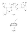
- the measuring rail 70 which is held on the guide rail 60, is exchangeable with measuring probes 80 of different strengths with measuring probe 80 having a predetermined thickness and guided against measuring rails 70.
- 13 shows such a measuring rail 70 with a measuring probe 80 arranged at the end.
- a number of measuring rails 70 with measuring probes 80 are available which have different thicknesses, such that measuring probes having different thicknesses have been introduced after the insertion of a plurality of measuring rails 70 80 then ultimately a measuring rail with a measuring probe inserted into the gap and the gap wrapped, so that then the predetermined total thickness a of the measuring rail with the probe is a measure of the width of the neck bearing game 50 ( Figure 8).
- the measuring rail 70 or the measuring rails have a length which is much greater than the length of the guide rail 60, so that a sufficient length of measuring rails 70 is available in order to be able to push the measuring probe 80 into the measuring range 40.
- the inventively embodied device 100 is used as follows:
- the angled guide rail section 60b of the guide rail 60 then lies in the interior of the rudder blade 15, specifically in the region of the gap 35 between the outer bearing 31 and the inner bearing 32 of the bearing 30 (FIG. 7).
- the measuring rail 70 is then moved on the guide rail 60, so that the free end of the measuring rail 70 is moved with the measuring probe 80 from the position A to the position B until the play measuring range 40 is reached.
- the measuring rail 70 is exchanged for a measuring rail with a measuring probe 80 whose overall thickness a is then selected larger is, as long as measuring rails are exchanged with measuring probes until a measuring rail 70 with a measuring probe 80 completely fills the game to be measured, in which case the total thickness of the measuring rail 70 with the measuring probe 80 corresponds to the width of the game. Since a number of measuring rails 70 are available with measuring probes 80 of different total thicknesses a, the width of the game can be measured effortlessly with appropriate selection of the measuring rail with the measuring probe.
- the device 100 according to the invention is particularly advantageous for use in controlling and measuring the neck bearing play of oars for watercraft, in particular of watercraft located in the dock or in the water by workers working above or underwater.
Landscapes
- Chemical & Material Sciences (AREA)
- Engineering & Computer Science (AREA)
- Combustion & Propulsion (AREA)
- Mechanical Engineering (AREA)
- Ocean & Marine Engineering (AREA)
- Physics & Mathematics (AREA)
- General Physics & Mathematics (AREA)
- A Measuring Device Byusing Mechanical Method (AREA)
- Length Measuring Devices With Unspecified Measuring Means (AREA)
- Length-Measuring Instruments Using Mechanical Means (AREA)
Applications Claiming Priority (2)
| Application Number | Priority Date | Filing Date | Title |
|---|---|---|---|
| DE202005017135 | 2005-10-31 | ||
| DE202005019626U DE202005019626U1 (de) | 2005-10-31 | 2005-12-13 | Vorrichtung zum Kontrollieren und Messen des Halslagerspiels des Ruderschaftes eines Ruders für Wasserfahrzeuge |
Publications (3)
| Publication Number | Publication Date |
|---|---|
| EP1780118A2 true EP1780118A2 (fr) | 2007-05-02 |
| EP1780118A3 EP1780118A3 (fr) | 2009-07-15 |
| EP1780118B1 EP1780118B1 (fr) | 2012-04-11 |
Family
ID=36121116
Family Applications (1)
| Application Number | Title | Priority Date | Filing Date |
|---|---|---|---|
| EP06016683A Not-in-force EP1780118B1 (fr) | 2005-10-31 | 2006-08-10 | Dispositif pour contrôler et mesurer le jeu entre la mèche de gouvernail d'un bateau et son palier |
Country Status (9)
| Country | Link |
|---|---|
| US (1) | US7516559B2 (fr) |
| EP (1) | EP1780118B1 (fr) |
| JP (1) | JP4431129B2 (fr) |
| KR (1) | KR100987578B1 (fr) |
| AT (1) | ATE553029T1 (fr) |
| CA (1) | CA2560609C (fr) |
| DE (1) | DE202005019626U1 (fr) |
| NO (1) | NO337985B1 (fr) |
| SG (1) | SG131837A1 (fr) |
Cited By (2)
| Publication number | Priority date | Publication date | Assignee | Title |
|---|---|---|---|---|
| DE102014110383A1 (de) * | 2014-04-01 | 2015-10-01 | Becker Marine Systems Gmbh & Co. Kg | Lager zum Lagern einer Welle, insbesondere eines Ruderschaftes, elektronische Lagerspielmessvorrichtung, Ruder umfassend ein Lager zum Lagern einer Welle und Verfahren zur Messung eines Verschleißes eines Lagers zum Lagern einer Welle |
| CN111044001A (zh) * | 2019-12-25 | 2020-04-21 | 中国人民解放军陆军航空兵学院陆军航空兵研究所 | 一种测量装置 |
Families Citing this family (15)
| Publication number | Priority date | Publication date | Assignee | Title |
|---|---|---|---|---|
| DE202007016164U1 (de) * | 2007-11-16 | 2008-01-24 | Becker Marine Systems Gmbh & Co. Kg | Hochleistungsruder für Schiffe |
| KR101034331B1 (ko) * | 2009-06-19 | 2011-05-16 | 대우조선해양 주식회사 | 선박의 러더 베어링 성능 검사 방법 |
| DE202009013211U1 (de) | 2009-09-02 | 2011-01-13 | Becker Marine Systems Gmbh & Co. Kg | Oberes Rudertraglager |
| DE202010004191U1 (de) | 2010-03-23 | 2010-07-01 | Van Der Velden Barkemeyer Gmbh | Ruder für Schiffe |
| CN101879930B (zh) * | 2010-07-19 | 2013-10-09 | 江苏华帝海洋工程设备制造有限公司 | 船舶舵系“三位一体”检测方法 |
| DE102011002832B4 (de) | 2011-01-18 | 2022-08-11 | Van Der Velden Barkemeyer Gmbh | Ruder für Schiffe mit einer Ruderüberwachungsvorrichtung |
| KR101228049B1 (ko) * | 2011-04-18 | 2013-01-30 | 현대중공업 주식회사 | 선박의 러더 스톡과 넥 베어링 사이의 틈새 검사 방법. |
| DE202013104463U1 (de) | 2013-10-01 | 2013-10-29 | Marifin Beheer B.V. | Ruder für Schiffe |
| CN105937872A (zh) * | 2016-06-30 | 2016-09-14 | 常州光洋轴承股份有限公司 | 一种组合式减速机主轴承单元游隙分组检测工装 |
| CN110186354A (zh) * | 2019-04-19 | 2019-08-30 | 沪东中华造船(集团)有限公司 | 一种船舶舵系间隙的测量方法 |
| CN111044000A (zh) * | 2019-12-25 | 2020-04-21 | 中国人民解放军陆军航空兵学院陆军航空兵研究所 | 一种测量装置 |
| DE202020103872U1 (de) * | 2020-07-03 | 2020-08-13 | Becker Marine Systems Gmbh | Ruderkoker für ein Wasserfahrzeug und Wasserfahrzeug mit einem Ruderkoker |
| CN113945182A (zh) * | 2021-11-23 | 2022-01-18 | 中车长春轨道客车股份有限公司 | 一种齿轮箱大齿轮轴承游隙测量装置 |
| CN114295032B (zh) * | 2021-12-21 | 2024-12-27 | 广东中远海运重工有限公司 | 一种带螺纹调节杆的舵系衬套间隙测量装置及方法 |
| KR102797101B1 (ko) | 2023-06-09 | 2025-04-21 | 주식회사 에스비씨리니어 | 윤축 베어링의 경방향 및 축방향 간극 측정장치 |
Citations (1)
| Publication number | Priority date | Publication date | Assignee | Title |
|---|---|---|---|---|
| JPH0914950A (ja) | 1995-06-28 | 1997-01-17 | Toshiba Corp | 狭隘部自動間隙計測器 |
Family Cites Families (15)
| Publication number | Priority date | Publication date | Assignee | Title |
|---|---|---|---|---|
| US2500137A (en) * | 1945-11-13 | 1950-03-07 | Wilma Poulton | Angle measuring instrument |
| US2520934A (en) * | 1947-11-19 | 1950-09-05 | Rolland C Hoy | Aircraft control surface rigging protractor |
| US3079692A (en) * | 1961-01-13 | 1963-03-05 | Norman L Mccracken | Journal lubricator clearance gauge |
| US3995373A (en) * | 1975-09-30 | 1976-12-07 | Brumbelow Dorsey R | Measuring device for ascertaining pipe diameter and depth location |
| US4462166A (en) * | 1982-07-01 | 1984-07-31 | Furlong Stanley J | Device for measuring lengths and conforming angles |
| US4536960A (en) * | 1984-07-13 | 1985-08-27 | Muti Elliott J | Calipers arranged for remote reading |
| US4744151A (en) * | 1987-03-30 | 1988-05-17 | Wisniewski Walter W | Surveying equipment |
| DE8708276U1 (de) * | 1987-06-12 | 1987-08-27 | Willi Becker Ingenieurbüro GmbH, 2000 Hamburg | Ruder, insbesondere Balance-Profilruder für Wasserfahrzeuge |
| JPH0299396U (fr) * | 1989-01-25 | 1990-08-08 | ||
| US5309644A (en) * | 1992-11-18 | 1994-05-10 | Robinson Jr Samuel P | Sewer invert elevation measuring instrument |
| JP3192978B2 (ja) * | 1996-10-01 | 2001-07-30 | 三菱重工業株式会社 | 隙間ゲージ |
| US20030226272A1 (en) * | 2002-06-10 | 2003-12-11 | Finefield Elwood S. | Precision invert measuring tool |
| US20050005467A1 (en) * | 2003-05-12 | 2005-01-13 | Hannel Johnathan S. | Measurement device for use with underground flow system and associated method |
| US7322252B1 (en) * | 2004-12-30 | 2008-01-29 | Rodgers Matthew E | Apparatus for taking measurements in access manholes |
| US7347002B2 (en) * | 2005-10-05 | 2008-03-25 | Robert Foege | Barrel measuring device |
-
2005
- 2005-12-13 DE DE202005019626U patent/DE202005019626U1/de not_active Expired - Lifetime
-
2006
- 2006-08-10 EP EP06016683A patent/EP1780118B1/fr not_active Not-in-force
- 2006-08-10 AT AT06016683T patent/ATE553029T1/de active
- 2006-09-05 SG SG200606110-5A patent/SG131837A1/en unknown
- 2006-09-11 KR KR1020060087297A patent/KR100987578B1/ko not_active Expired - Fee Related
- 2006-09-21 CA CA002560609A patent/CA2560609C/fr not_active Expired - Fee Related
- 2006-09-22 US US11/526,139 patent/US7516559B2/en not_active Expired - Fee Related
- 2006-10-03 JP JP2006271418A patent/JP4431129B2/ja not_active Expired - Fee Related
- 2006-10-27 NO NO20064931A patent/NO337985B1/no not_active IP Right Cessation
Patent Citations (1)
| Publication number | Priority date | Publication date | Assignee | Title |
|---|---|---|---|---|
| JPH0914950A (ja) | 1995-06-28 | 1997-01-17 | Toshiba Corp | 狭隘部自動間隙計測器 |
Cited By (3)
| Publication number | Priority date | Publication date | Assignee | Title |
|---|---|---|---|---|
| DE102014110383A1 (de) * | 2014-04-01 | 2015-10-01 | Becker Marine Systems Gmbh & Co. Kg | Lager zum Lagern einer Welle, insbesondere eines Ruderschaftes, elektronische Lagerspielmessvorrichtung, Ruder umfassend ein Lager zum Lagern einer Welle und Verfahren zur Messung eines Verschleißes eines Lagers zum Lagern einer Welle |
| US10066662B2 (en) | 2014-04-01 | 2018-09-04 | Becker Marine Systems Gmbh & Co. Kg | Bearing for supporting a shaft, in particular a rudder shaft, or a rudder blade, electronic bearing clearance measuring device, rudder comprising a bearing for supporting a shaft or a rudder blade, and method for measuring wear of a bearing for supporting a shaft or a rudder blade |
| CN111044001A (zh) * | 2019-12-25 | 2020-04-21 | 中国人民解放军陆军航空兵学院陆军航空兵研究所 | 一种测量装置 |
Also Published As
| Publication number | Publication date |
|---|---|
| US7516559B2 (en) | 2009-04-14 |
| CA2560609A1 (fr) | 2007-04-30 |
| DE202005019626U1 (de) | 2006-03-16 |
| EP1780118B1 (fr) | 2012-04-11 |
| KR100987578B1 (ko) | 2010-10-12 |
| NO337985B1 (no) | 2016-07-18 |
| EP1780118A3 (fr) | 2009-07-15 |
| US20070094881A1 (en) | 2007-05-03 |
| SG131837A1 (en) | 2007-05-28 |
| KR20070046708A (ko) | 2007-05-03 |
| NO20064931L (no) | 2007-05-02 |
| JP4431129B2 (ja) | 2010-03-10 |
| JP2007126130A (ja) | 2007-05-24 |
| ATE553029T1 (de) | 2012-04-15 |
| CA2560609C (fr) | 2009-11-17 |
Similar Documents
| Publication | Publication Date | Title |
|---|---|---|
| EP1780118B1 (fr) | Dispositif pour contrôler et mesurer le jeu entre la mèche de gouvernail d'un bateau et son palier | |
| DE202010004191U1 (de) | Ruder für Schiffe | |
| WO1986006343A1 (fr) | Arc-boutants coulissants | |
| DD139558A5 (de) | Oelsammelschiff | |
| DE3330396A1 (de) | Messvorrichtung zur bestimmung des durchmessers von rundhoelzern od. dgl. | |
| DE102011111797B4 (de) | Unterseeboot mit einer Handkurbel für einen Geräteantrieb | |
| DE20019098U1 (de) | Kettenmarkierung, insbesondere für Ankerketten | |
| DE2441007A1 (de) | Verfahren und vorrichtung zur messung der entfernung zwischen zwei punkten laengs eines kreisfoermigen verbindungsbogens mit unbekanntem radius | |
| DE3242290C2 (de) | Abweiser an Antriebs- und Steuereinrichtungen von Schiffen | |
| DE427517C (de) | Vorrichtung, um aus der Entfernung den Fluessigkeitsspiegel in einem Behaelter mit Hilfe eines beweglichen Organs zu bestimmen | |
| DE2854472C2 (de) | Trockendock zum Schiffsneubau und Verfahren zum Bau von Schiffen in diesem Trockendock | |
| DE697987C (de) | Vorrichtung zur Fortbewegung eines Ruderbootes durch Zugkraft in der Gesichtsrichtung des Ruderers | |
| DE20023702U1 (de) | Vorrichtung zum Reinigen der Rumpfaußenseite eines Bootes | |
| DE2830429C3 (de) | Schotklemme mit Klemmrollen | |
| EP0043064A1 (fr) | Aviron pour bateau à ramer | |
| DE273365C (fr) | ||
| DE1179824B (de) | Verfahren zum Herstellen von Teilen von Boots-ruempfen und/oder Formteilen zum Herstellen derselben | |
| DE1798086A1 (de) | Messeinrichtung zur Ermittlung der Standhoehe einer im Behaelter stehenden Fluessigkeitssaeule | |
| DE119191C (fr) | ||
| DE3333352C1 (de) | Mastfussanordnung für ein Segelbrett | |
| DE102015118615B3 (de) | Flexible Lanze zum Bearbeiten oder Inspizieren eines Rohrbodens eines Dampferzeugers | |
| DE1924454A1 (de) | Vorrichtung zum Herstellen oder Pruefen der Form von Blechteilen | |
| DE69608511T2 (de) | Kraftfahrzeug-Scheibenwischer mit Befestigungsvorrichtung für die Waschwasser-Rohrleitung | |
| DE8317177U1 (de) | Vorrichtung zur Untersuchung von Bodenproben auf Scherfestigkeit | |
| DE2548315A1 (de) | Nadelstabkette in nadelstabstreckwerken |
Legal Events
| Date | Code | Title | Description |
|---|---|---|---|
| PUAI | Public reference made under article 153(3) epc to a published international application that has entered the european phase |
Free format text: ORIGINAL CODE: 0009012 |
|
| AK | Designated contracting states |
Kind code of ref document: A2 Designated state(s): AT BE BG CH CY CZ DE DK EE ES FI FR GB GR HU IE IS IT LI LT LU LV MC NL PL PT RO SE SI SK TR |
|
| AX | Request for extension of the european patent |
Extension state: AL BA HR MK YU |
|
| 17P | Request for examination filed |
Effective date: 20080509 |
|
| PUAL | Search report despatched |
Free format text: ORIGINAL CODE: 0009013 |
|
| AK | Designated contracting states |
Kind code of ref document: A3 Designated state(s): AT BE BG CH CY CZ DE DK EE ES FI FR GB GR HU IE IS IT LI LT LU LV MC NL PL PT RO SE SI SK TR |
|
| AX | Request for extension of the european patent |
Extension state: AL BA HR MK RS |
|
| RIC1 | Information provided on ipc code assigned before grant |
Ipc: G01B 5/14 20060101ALI20090609BHEP Ipc: G01B 5/02 20060101ALI20090609BHEP Ipc: B63H 25/38 20060101ALI20090609BHEP Ipc: B63B 3/40 20060101ALI20090609BHEP Ipc: B63H 25/52 20060101AFI20070223BHEP |
|
| AKX | Designation fees paid |
Designated state(s): AT BE BG CH CY CZ DE DK EE ES FI FR GB GR HU IE IS IT LI LT LU LV MC NL PL PT RO SE SI SK TR |
|
| GRAP | Despatch of communication of intention to grant a patent |
Free format text: ORIGINAL CODE: EPIDOSNIGR1 |
|
| GRAS | Grant fee paid |
Free format text: ORIGINAL CODE: EPIDOSNIGR3 |
|
| RTI1 | Title (correction) |
Free format text: ARRANGEMENT FOR CONTROLLING AND MEASURING THE CLEARANCE BETWEEN THE RUDDER STOCK BEARING AND THE RUDDER STOCK IN A WATERCRAFT |
|
| GRAA | (expected) grant |
Free format text: ORIGINAL CODE: 0009210 |
|
| AK | Designated contracting states |
Kind code of ref document: B1 Designated state(s): AT BE BG CH CY CZ DE DK EE ES FI FR GB GR HU IE IS IT LI LT LU LV MC NL PL PT RO SE SI SK TR |
|
| REG | Reference to a national code |
Ref country code: GB Ref legal event code: FG4D Free format text: NOT ENGLISH |
|
| REG | Reference to a national code |
Ref country code: DE Ref legal event code: R081 Ref document number: 502006011262 Country of ref document: DE Owner name: BECKER MARINE SYSTEMS GMBH, DE Free format text: FORMER OWNER: BECKER MARINE SYSTEMS GMBH & CO. KG, 21079 HAMBURG, DE Ref country code: CH Ref legal event code: EP |
|
| REG | Reference to a national code |
Ref country code: AT Ref legal event code: REF Ref document number: 553029 Country of ref document: AT Kind code of ref document: T Effective date: 20120415 |
|
| REG | Reference to a national code |
Ref country code: IE Ref legal event code: FG4D Free format text: LANGUAGE OF EP DOCUMENT: GERMAN |
|
| REG | Reference to a national code |
Ref country code: DE Ref legal event code: R096 Ref document number: 502006011262 Country of ref document: DE Effective date: 20120606 |
|
| REG | Reference to a national code |
Ref country code: RO Ref legal event code: EPE |
|
| REG | Reference to a national code |
Ref country code: NL Ref legal event code: T3 |
|
| LTIE | Lt: invalidation of european patent or patent extension |
Effective date: 20120411 |
|
| REG | Reference to a national code |
Ref country code: GR Ref legal event code: EP Ref document number: 20120401546 Country of ref document: GR Effective date: 20120903 |
|
| PG25 | Lapsed in a contracting state [announced via postgrant information from national office to epo] |
Ref country code: LT Free format text: LAPSE BECAUSE OF FAILURE TO SUBMIT A TRANSLATION OF THE DESCRIPTION OR TO PAY THE FEE WITHIN THE PRESCRIBED TIME-LIMIT Effective date: 20120411 Ref country code: PL Free format text: LAPSE BECAUSE OF FAILURE TO SUBMIT A TRANSLATION OF THE DESCRIPTION OR TO PAY THE FEE WITHIN THE PRESCRIBED TIME-LIMIT Effective date: 20120411 Ref country code: CY Free format text: LAPSE BECAUSE OF FAILURE TO SUBMIT A TRANSLATION OF THE DESCRIPTION OR TO PAY THE FEE WITHIN THE PRESCRIBED TIME-LIMIT Effective date: 20120411 Ref country code: IS Free format text: LAPSE BECAUSE OF FAILURE TO SUBMIT A TRANSLATION OF THE DESCRIPTION OR TO PAY THE FEE WITHIN THE PRESCRIBED TIME-LIMIT Effective date: 20120811 Ref country code: SE Free format text: LAPSE BECAUSE OF FAILURE TO SUBMIT A TRANSLATION OF THE DESCRIPTION OR TO PAY THE FEE WITHIN THE PRESCRIBED TIME-LIMIT Effective date: 20120411 |
|
| PG25 | Lapsed in a contracting state [announced via postgrant information from national office to epo] |
Ref country code: SI Free format text: LAPSE BECAUSE OF FAILURE TO SUBMIT A TRANSLATION OF THE DESCRIPTION OR TO PAY THE FEE WITHIN THE PRESCRIBED TIME-LIMIT Effective date: 20120411 Ref country code: LV Free format text: LAPSE BECAUSE OF FAILURE TO SUBMIT A TRANSLATION OF THE DESCRIPTION OR TO PAY THE FEE WITHIN THE PRESCRIBED TIME-LIMIT Effective date: 20120411 Ref country code: PT Free format text: LAPSE BECAUSE OF FAILURE TO SUBMIT A TRANSLATION OF THE DESCRIPTION OR TO PAY THE FEE WITHIN THE PRESCRIBED TIME-LIMIT Effective date: 20120813 |
|
| PG25 | Lapsed in a contracting state [announced via postgrant information from national office to epo] |
Ref country code: EE Free format text: LAPSE BECAUSE OF FAILURE TO SUBMIT A TRANSLATION OF THE DESCRIPTION OR TO PAY THE FEE WITHIN THE PRESCRIBED TIME-LIMIT Effective date: 20120411 Ref country code: SK Free format text: LAPSE BECAUSE OF FAILURE TO SUBMIT A TRANSLATION OF THE DESCRIPTION OR TO PAY THE FEE WITHIN THE PRESCRIBED TIME-LIMIT Effective date: 20120411 Ref country code: CZ Free format text: LAPSE BECAUSE OF FAILURE TO SUBMIT A TRANSLATION OF THE DESCRIPTION OR TO PAY THE FEE WITHIN THE PRESCRIBED TIME-LIMIT Effective date: 20120411 Ref country code: DK Free format text: LAPSE BECAUSE OF FAILURE TO SUBMIT A TRANSLATION OF THE DESCRIPTION OR TO PAY THE FEE WITHIN THE PRESCRIBED TIME-LIMIT Effective date: 20120411 |
|
| PLBE | No opposition filed within time limit |
Free format text: ORIGINAL CODE: 0009261 |
|
| STAA | Information on the status of an ep patent application or granted ep patent |
Free format text: STATUS: NO OPPOSITION FILED WITHIN TIME LIMIT |
|
| BERE | Be: lapsed |
Owner name: BECKER MARINE SYSTEMS G.M.B.H. & CO. KG Effective date: 20120831 |
|
| 26N | No opposition filed |
Effective date: 20130114 |
|
| REG | Reference to a national code |
Ref country code: CH Ref legal event code: PL |
|
| PG25 | Lapsed in a contracting state [announced via postgrant information from national office to epo] |
Ref country code: MC Free format text: LAPSE BECAUSE OF NON-PAYMENT OF DUE FEES Effective date: 20120831 |
|
| GBPC | Gb: european patent ceased through non-payment of renewal fee |
Effective date: 20120810 |
|
| PG25 | Lapsed in a contracting state [announced via postgrant information from national office to epo] |
Ref country code: ES Free format text: LAPSE BECAUSE OF FAILURE TO SUBMIT A TRANSLATION OF THE DESCRIPTION OR TO PAY THE FEE WITHIN THE PRESCRIBED TIME-LIMIT Effective date: 20120722 Ref country code: CH Free format text: LAPSE BECAUSE OF NON-PAYMENT OF DUE FEES Effective date: 20120831 Ref country code: LI Free format text: LAPSE BECAUSE OF NON-PAYMENT OF DUE FEES Effective date: 20120831 |
|
| REG | Reference to a national code |
Ref country code: DE Ref legal event code: R097 Ref document number: 502006011262 Country of ref document: DE Effective date: 20130114 |
|
| REG | Reference to a national code |
Ref country code: IE Ref legal event code: MM4A |
|
| PG25 | Lapsed in a contracting state [announced via postgrant information from national office to epo] |
Ref country code: BE Free format text: LAPSE BECAUSE OF NON-PAYMENT OF DUE FEES Effective date: 20120831 |
|
| PG25 | Lapsed in a contracting state [announced via postgrant information from national office to epo] |
Ref country code: GB Free format text: LAPSE BECAUSE OF NON-PAYMENT OF DUE FEES Effective date: 20120810 Ref country code: IE Free format text: LAPSE BECAUSE OF NON-PAYMENT OF DUE FEES Effective date: 20120810 Ref country code: BG Free format text: LAPSE BECAUSE OF FAILURE TO SUBMIT A TRANSLATION OF THE DESCRIPTION OR TO PAY THE FEE WITHIN THE PRESCRIBED TIME-LIMIT Effective date: 20120711 |
|
| REG | Reference to a national code |
Ref country code: AT Ref legal event code: MM01 Ref document number: 553029 Country of ref document: AT Kind code of ref document: T Effective date: 20120831 |
|
| PG25 | Lapsed in a contracting state [announced via postgrant information from national office to epo] |
Ref country code: AT Free format text: LAPSE BECAUSE OF NON-PAYMENT OF DUE FEES Effective date: 20120831 |
|
| PG25 | Lapsed in a contracting state [announced via postgrant information from national office to epo] |
Ref country code: TR Free format text: LAPSE BECAUSE OF FAILURE TO SUBMIT A TRANSLATION OF THE DESCRIPTION OR TO PAY THE FEE WITHIN THE PRESCRIBED TIME-LIMIT Effective date: 20120411 |
|
| PG25 | Lapsed in a contracting state [announced via postgrant information from national office to epo] |
Ref country code: LU Free format text: LAPSE BECAUSE OF NON-PAYMENT OF DUE FEES Effective date: 20120810 |
|
| PG25 | Lapsed in a contracting state [announced via postgrant information from national office to epo] |
Ref country code: HU Free format text: LAPSE BECAUSE OF FAILURE TO SUBMIT A TRANSLATION OF THE DESCRIPTION OR TO PAY THE FEE WITHIN THE PRESCRIBED TIME-LIMIT Effective date: 20060810 |
|
| REG | Reference to a national code |
Ref country code: FR Ref legal event code: PLFP Year of fee payment: 11 |
|
| PGFP | Annual fee paid to national office [announced via postgrant information from national office to epo] |
Ref country code: GR Payment date: 20170616 Year of fee payment: 12 |
|
| REG | Reference to a national code |
Ref country code: FR Ref legal event code: PLFP Year of fee payment: 12 |
|
| PGFP | Annual fee paid to national office [announced via postgrant information from national office to epo] |
Ref country code: CH Payment date: 20170724 Year of fee payment: 12 |
|
| REG | Reference to a national code |
Ref country code: DE Ref legal event code: R082 Ref document number: 502006011262 Country of ref document: DE Representative=s name: RGTH RICHTER GERBAULET THIELEMANN HOFMANN PATE, DE Ref country code: DE Ref legal event code: R081 Ref document number: 502006011262 Country of ref document: DE Owner name: BECKER MARINE SYSTEMS GMBH, DE Free format text: FORMER OWNER: BECKER MARINE SYSTEMS GMBH & CO. KG, 21079 HAMBURG, DE |
|
| REG | Reference to a national code |
Ref country code: FR Ref legal event code: PLFP Year of fee payment: 13 |
|
| PGFP | Annual fee paid to national office [announced via postgrant information from national office to epo] |
Ref country code: DE Payment date: 20181026 Year of fee payment: 13 |
|
| PG25 | Lapsed in a contracting state [announced via postgrant information from national office to epo] |
Ref country code: RO Free format text: LAPSE BECAUSE OF NON-PAYMENT OF DUE FEES Effective date: 20180810 |
|
| PG25 | Lapsed in a contracting state [announced via postgrant information from national office to epo] |
Ref country code: GR Free format text: LAPSE BECAUSE OF NON-PAYMENT OF DUE FEES Effective date: 20190307 |
|
| PGFP | Annual fee paid to national office [announced via postgrant information from national office to epo] |
Ref country code: FR Payment date: 20190822 Year of fee payment: 14 Ref country code: IT Payment date: 20190821 Year of fee payment: 14 Ref country code: FI Payment date: 20190820 Year of fee payment: 14 |
|
| REG | Reference to a national code |
Ref country code: DE Ref legal event code: R119 Ref document number: 502006011262 Country of ref document: DE |
|
| PG25 | Lapsed in a contracting state [announced via postgrant information from national office to epo] |
Ref country code: DE Free format text: LAPSE BECAUSE OF NON-PAYMENT OF DUE FEES Effective date: 20200303 |
|
| REG | Reference to a national code |
Ref country code: FI Ref legal event code: MAE |
|
| PG25 | Lapsed in a contracting state [announced via postgrant information from national office to epo] |
Ref country code: FI Free format text: LAPSE BECAUSE OF NON-PAYMENT OF DUE FEES Effective date: 20200810 |
|
| PG25 | Lapsed in a contracting state [announced via postgrant information from national office to epo] |
Ref country code: FR Free format text: LAPSE BECAUSE OF NON-PAYMENT OF DUE FEES Effective date: 20200831 Ref country code: IT Free format text: LAPSE BECAUSE OF NON-PAYMENT OF DUE FEES Effective date: 20200810 |
|
| PGFP | Annual fee paid to national office [announced via postgrant information from national office to epo] |
Ref country code: NL Payment date: 20220822 Year of fee payment: 17 |
|
| REG | Reference to a national code |
Ref country code: NL Ref legal event code: MM Effective date: 20230901 |
|
| PG25 | Lapsed in a contracting state [announced via postgrant information from national office to epo] |
Ref country code: NL Free format text: LAPSE BECAUSE OF NON-PAYMENT OF DUE FEES Effective date: 20230901 |
|
| PG25 | Lapsed in a contracting state [announced via postgrant information from national office to epo] |
Ref country code: NL Free format text: LAPSE BECAUSE OF NON-PAYMENT OF DUE FEES Effective date: 20230901 |