EP1780121B1 - Rotorblatt versehen mit einer schwenbaren Klappe und mit einer Befestigungslasche - Google Patents
Rotorblatt versehen mit einer schwenbaren Klappe und mit einer Befestigungslasche Download PDFInfo
- Publication number
- EP1780121B1 EP1780121B1 EP06021788A EP06021788A EP1780121B1 EP 1780121 B1 EP1780121 B1 EP 1780121B1 EP 06021788 A EP06021788 A EP 06021788A EP 06021788 A EP06021788 A EP 06021788A EP 1780121 B1 EP1780121 B1 EP 1780121B1
- Authority
- EP
- European Patent Office
- Prior art keywords
- flap
- blade
- tongue
- blade according
- trailing edge
- Prior art date
- Legal status (The legal status is an assumption and is not a legal conclusion. Google has not performed a legal analysis and makes no representation as to the accuracy of the status listed.)
- Ceased
Links
Images

Classifications
-
- B—PERFORMING OPERATIONS; TRANSPORTING
- B64—AIRCRAFT; AVIATION; COSMONAUTICS
- B64C—AEROPLANES; HELICOPTERS
- B64C27/00—Rotorcraft; Rotors peculiar thereto
- B64C27/54—Mechanisms for controlling blade adjustment or movement relative to rotor head, e.g. lag-lead movement
- B64C27/58—Transmitting means, e.g. interrelated with initiating means or means acting on blades
- B64C27/59—Transmitting means, e.g. interrelated with initiating means or means acting on blades mechanical
- B64C27/615—Transmitting means, e.g. interrelated with initiating means or means acting on blades mechanical including flaps mounted on blades
-
- B—PERFORMING OPERATIONS; TRANSPORTING
- B64—AIRCRAFT; AVIATION; COSMONAUTICS
- B64C—AEROPLANES; HELICOPTERS
- B64C27/00—Rotorcraft; Rotors peculiar thereto
- B64C27/54—Mechanisms for controlling blade adjustment or movement relative to rotor head, e.g. lag-lead movement
- B64C27/72—Means acting on blades
- B64C2027/7205—Means acting on blades on each blade individually, e.g. individual blade control [IBC]
- B64C2027/7261—Means acting on blades on each blade individually, e.g. individual blade control [IBC] with flaps
- B64C2027/7266—Means acting on blades on each blade individually, e.g. individual blade control [IBC] with flaps actuated by actuators
- B64C2027/7272—Means acting on blades on each blade individually, e.g. individual blade control [IBC] with flaps actuated by actuators of the electro-hydraulic type
-
- Y—GENERAL TAGGING OF NEW TECHNOLOGICAL DEVELOPMENTS; GENERAL TAGGING OF CROSS-SECTIONAL TECHNOLOGIES SPANNING OVER SEVERAL SECTIONS OF THE IPC; TECHNICAL SUBJECTS COVERED BY FORMER USPC CROSS-REFERENCE ART COLLECTIONS [XRACs] AND DIGESTS
- Y02—TECHNOLOGIES OR APPLICATIONS FOR MITIGATION OR ADAPTATION AGAINST CLIMATE CHANGE
- Y02T—CLIMATE CHANGE MITIGATION TECHNOLOGIES RELATED TO TRANSPORTATION
- Y02T50/00—Aeronautics or air transport
- Y02T50/30—Wing lift efficiency
Definitions
- the present invention relates to a rotorcraft active blade provided at its trailing edge with a fixing tongue and an adjustable flap controlled locally by an electromechanical device.
- the steering angle of the flap relative to the blade is of the order of plus or minus 10 degrees at a frequency of the order of 30 Hz.
- the steering angle varies actively over time depending on many parameters such as the position of the blade around the axis of the main rotor, so-called “azimuth" position, the speed of rotation of the rotor main and the movements of the blade in step, beat and drag.
- the upper and lower parts are each connected to an actuator while the concave central portion is disposed against a knee secured to the blade. Therefore, by activating one or other of the actuators, the flap tilts around the knee so as to present the desired inclination.
- the overall shape of the flap and more particularly the leading edge of this flap is not optimized from an aerodynamic point of view which can possibly be the cause of acoustic or vibratory discomfort and degradations of aerodynamic performance.
- the flap is fixed to the blade by a longitudinal axis, that is to say disposed along the span of the blade, which passes through the flap.
- the flap is able to rotate about this longitudinal axis by being set in motion by an articulated link secured to the underside of the shutter, this rod being itself controlled by an actuator.
- the rod is thus located partially outside the blade / shutter assembly which affects the aerodynamics of the assembly Moreover, there is a discontinuity between the flap and the blade which can cause a weakening of the aerodynamic performance and a whistling effect due to the air circulation between the shutter and the blade.
- This second type of architecture for which the shutter rotates about an axis, still has the disadvantage of causing a possible blockage of the shutter. Indeed, we must not lose sight of the fact that the mechanical stresses exerted on the flap and the blade during the flight are very important. There is therefore a significant risk of attending a deformation of the axis, the shutter can not therefore be turned to the desired inclination.
- a third type of blade equipped with a flap is not connected to the blade by a longitudinal axis but by two pins arranged on each side of the flap.
- the flap is provided with a flexible arm which is positioned inside the blade being connected, via a lever, to a set of two rotary motors acting on coaxial eccentrics. With the aid of this set of two rotary motors, the device controls the inclination of the flexible arm and thus of the shutter.
- the present invention aims to provide an active blade provided with a flap and a fastening tab to overcome the limitations of the blades mentioned above.
- the rotorcraft blades are extremely thin, that is to say that the relative thickness of the sections of the blade is small, so that the thickness of the blade is low and that especially at their trailing edge where the thickness decreases.
- the maximum thickness of the flap is of the order of 20 millimeters. It will be said that in such a case the device allowing the inclination of the flap relative to the blade must be compact to be housed in the blade and / or the flap.
- a rotorcraft rotor blade comprises at least one orientable trailing edge flap, this flap being able to pivot about a virtual hinge axis oriented substantially along the span of said blade and of said flap.
- blade is remarkable in that the flap is provided with at least two fastening spheres each provided with an inner cage as well as an outer cage and a first shaft which is further secured to said flap, the first shaft of fastening ball joints being substantially perpendicular to the virtual hinge axis of rotation of the flap.
- the blade is equipped with a fixing tongue provided with swiveling points, the outer cages of the fixing ball joints then being secured to said swiveling points.
- the fastening ball joints then constitute pivots around which the flap is able to pivot to present the desired inclination relative to the blade.
- this configuration is very original since the first shaft of each fixing ball is not coincident with the virtual hinge axis of rotation of the flap or at least directed thereto.
- this first shaft is preferably perpendicular to the virtual hinge axis and substantially perpendicular to the plane of the strings of the flap, that is to say approximately directed according to the thickness of the flap. This is of great importance insofar as it becomes possible to arrange a kneecap in a space that is however very small.
- the blade having an upper surface and a lower surface, these upper and lower surfaces meet at the trailing edge of the blade in order to form the tongue so as to obtain in particular a rigid tongue.
- the rigidity of the tongue avoids a large loss of effectiveness of the shutter by preventing a moment of return that would be induced by a flexible tongue.
- the blade having a rib near its trailing edge, the tongue is substantially mid-height of the rib.
- the flap comprises an opening provided with a lower lip and an upper lip, said tongue being arranged between these upper and lower lips when said flap is fixed to said blade.
- the lower and upper lips then describe an angular field of the order of 20 ° to allow the flap to present the required inclinations relative to the blade.
- This inclination of the flap relative to the blade is controlled using at least one control arm, integral with the flap, which is controlled by a linear or rotary actuator, arranged in the blade.
- a linear or rotary actuator arranged in the blade.
- the tongue is of great importance for aerodynamic and acoustic reasons. It makes it possible to eliminate a discontinuity between the shutter and the blade thus avoiding air circulation between them. This advantage is maximized when the tongue extends along the span of the flap, that is to say when the tongue has at least the same length as the flap.
- the tongue comprises at least two distinct portions separated from each other by a control arm.
- the tongue comprises a flexible tape, elastomer for example, at its free end, that is to say at the end of the tongue located on the trailing edge of the flap and not the side of the trailing edge of the blade.
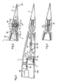
- the figure 1 shows a schematic view of a blade equipped with a shutter according to the invention.
- a rotorcraft blade 1 is provided with a trailing edge flap 5.
- two electromechanical actuators 10, 10 ' are arranged inside the box 4 of the blade 1 which is disposed between the spar 3 and the rib 2 of the blade 1.
- the actuators 10, 10 allow the trailing edge flap 5 to pivot about the virtual hinge axis Y', each via a control arm 46 integral with the flap, in order to improve the aeroaccoustic, aerodynamic and vibratory performance of the 1. They are themselves controlled by an electronic box, not shown in the figures, which provides the shutter control law (steering angle / frequency) according to the flight configuration of the rotorcraft.
- the actuators 10, 10 ' are further electrically powered by a collector disposed at the rotor of the rotorcraft via an electrical circuit integrated with the blade 1 along its span.
- position sensors send signals to the control unit so that the control unit can slave the shutter.
- the system will be in passive mode, the flap 5 then remaining immobilized in neutral position in the extension of the base profile of the blade 1.
- one or more flaps are arranged on the blade 1, preferably in the vicinity of the salmon thereof, that is to say towards the free end of the blade.
- a different number of actuators can be provided.
- the flap 5 is fixed to the blade 1 by means of two attachment joints, not shown on the figure 1 , and a tongue 20 arranged at the trailing edge BF of the blade 1.
- the fixing balls are each provided with an internal cage and a outer cage and a first shaft 31, the outer cages being secured to the swiveling points 21 of the tongue.
- the tongue 20 extends along the span of the flap 5.
- the tongue has several portions 20 ', 20 ", 20' '', two adjacent portions 20'-20", 20 "-20 '' 'being separated by a control arm 46.
- the passage of air between the flap 5 and the blade 1 is prevented either by a tongue portion or by a control arm.
- the figure 2 presents a section of the figure 1 , showing an area of the flap 50 provided with a fixing ball.
- the upper surface 50 and lower surface 6 of the blade 1 meet at the trailing edge BF so as to form the tongue 20.
- the trailing edge BF has the flap 5 a concave face which improves the aerodynamics of the 'together.
- the tongue 20 is located midway up the rib 7 located at the trailing edge BF of the blade 1.
- the flap 5 being provided with an opening provided with an upper lip 5 'and a lower lip 5 ", the tongue is arranged between the upper 5' and lower 5" lips.
- the upper 5 'and lower 5 "lips describe an angular field ⁇ of the order of 20 ° to allow the flap 5 the required inclinations.
- the flap 5 comprises a fixing ball 30 provided with an inner cage 32, an outer cage 33 and a first shaft 31.
- This first shaft 31 is secured to the flap 5, a tilting of the first shaft 31 causing a tilting of the flap 5 and vice versa.
- the first shaft 31 passes partially through the flap 5, these ends being fastened to the flap 5 by means of a nut 31 ', 31 "for example
- the first shaft 31 is substantially perpendicular to the flange 5. virtual hinge axis Y 'and the plane of the strings P of the flap 5, the first shaft 31 then extending according to the thickness of the flap 5.
- the flap 5 is connected to the blade 1 via the outer cage 33 of the attachment ball 30. More specifically, the outer cage 33, which includes the inner cage 32 is secured to the point of rotulage 21 so as to actually represent a corrugated insert, the outer cage 33 being integral with the tongue 20.
- the latter are, if necessary, prestressed to cancel the clearance separating their internal and external cages 32 and 33.
- the centrifugal forces applying to the flap / fastener assembly exert a natural prestressing on the attachment joints in the direction of the span of the blade. If the level of this prestressing is sufficiently high, the cages internal 32 and outer 33 attachment ball 30 always remain in contact despite the other efforts (dynamic, aerodynamic and control) to which they are subject in the direction of the rope of the blade.
- the blade then comprises a spring-type device introduced between the flap 5 and the trailing edge BF of the blade 1, which makes it possible to exert a permanent force tending, for example, to move the flap 5 away from the trailing edge of the blade. the blade.
- the free end EX of the tongue 20 is provided with a flexible tape 22, made of elastomer for example, this free end being on the side of the trailing edge BF 'of the flap 5 and not on the trailing edge side. BF of the blade 1.
- This ribbon is all the more useful since it prevents the circulation of air between the flap 5 and the blade 1, and more precisely between the free end EX of the tongue 20 and the flap 5. Moreover, its flexibility, the flexible ribbon 22 will not hinder the tilting of the flap 5.
- the figure 3 presents a section of the figure 1 showing a zone of the flap 5 provided with the control arm according to a first embodiment.
- control arm 46 is secured to the flap 5 being for example embedded in the latter at the time of manufacture. An inclination of the arm command 46 will therefore lead to a similar inclination of the flap 5.
- the actuator 10 is of linear type, its end 11 being able to move along the X axis in accordance with the arrows F. It will be noted the presence of access hatches 100 on the underside of the blade 1 to allow maintenance operations on the actuator 10 for example.
- the transmission chain for connecting the actuator 10 to the flap 5 successively comprises a first connecting rod 40, an angled arm 41, an expandable flexible pivot 43 and the control arm 46.
- the first connecting rod 40 which also passes through the rib 2, is on the one hand fixed to the end 11 of the actuator and on the other hand to the bent arm 41 and more particularly to the primary arm 41 'of the bent arm 41 .
- this bent arm 41 is attached to a support 42 by means of a through shaft 42 ', the support 42 being integral with the rib 2.
- the bent arm 41 can pivot around the through tree 42 '.
- crank arm 41 "of the crank arm 41 is connected to the control arm 46 via a flexible pivot 43.
- a pivoting of the crank arm 41 will consequently result in the tilting of the control arm 46 and therefore of the flap 5, taking into account the facts mentioned above.
- the flexible flexible pivot 43 then comprises a conventional single pivot 43 ', a threaded sleeve 43' 'and a rod 43 "'.
- the single pivot is on the one hand connected to the secondary arm 41" of the elbow arm 41 and on the other hand to the stem 43 '' '.
- This rod 43 '' ' is fitted into the threaded sleeve 43 ", itself fixed on the control arm 46.
- the sliding fit of the rod 43' '' in the threaded sleeve then allows movement of the rod 43 '' 'with respect to the threaded sleeve 43 "along the X axis.
- the actuator is of the rotary type.
- a device as previously described for example, allowing elongation along the X axis then being arranged between the control arm 46 and the rotary actuator.
- the figure 4 presents a section of the figure 1 in an area of the flap 5 having neither a fixing ball 30 nor a control arm 46.
Landscapes
- Engineering & Computer Science (AREA)
- Mechanical Engineering (AREA)
- Aviation & Aerospace Engineering (AREA)
- Toys (AREA)
Claims (10)
- Rotorblatt (1) eines Drehflüglers, das mindestens eine verstellbare Hinterkantenklappe (5) aufweist, wobei die Klappe (5) fähig ist, eine Schwenkbewegung um eine virtuelle Scharnierachse (Y') auszuführen, die im Wesentlichen gemäß der Spannbreite des Blatts (1) und der Klappe (5) ausgerichtet ist,
dadurch gekennzeichnet, dass die Klappe (5) mindestens zwei Befestigungs-Kugelgelenke (30) aufweist, die je mit einem inneren Käfig (32) sowie mit einem äußeren Käfig (33) und mit einer fest mit der Klappe (5) verbundenen ersten Welle (31) versehen sind, wobei das Blatt an seiner Hinterkante (BF) mit einer Befestigungszunge (20) versehen ist, die mit Drehpunkten (21) ausgestattet ist, wobei die äußeren Käfige (33) der Befestigungs-Kugelgelenke (30) fest mit den Drehpunkten (21) verbunden werden. - Blatt nach Anspruch 1, dadurch gekennzeichnet, dass die erste Welle (31) der Befestigungs-Kugelgelenke (30) lotrecht zur virtuellen Drehscharnierachse (Y') der Klappe (5) liegt.
- Blatt nach einem der vorhergehenden Ansprüche, dadurch gekennzeichnet, dass, wenn das Blatt (1) eine Oberseite (50) und eine Unterseite (6) aufweist, die Oberseite (50) und die Unterseite (6) sich in Höhe der Hinterkante (BF) des Blatts (1) vereinen, um die Zunge (20) zu bilden.
- Blatt nach einem der vorhergehenden Ansprüche, dadurch gekennzeichnet, dass, wenn das Blatt (1) eine Rippe (7) in der Nähe seiner Hinterkante (BF) aufweist, die Zunge (20) sich im Wesentlichen auf halber Höhe der Rippe (7) befindet.
- Blatt nach einem der vorhergehenden Ansprüche, dadurch gekennzeichnet, dass die Zunge (20) starr ist.
- Blatt nach einem der vorhergehenden Ansprüche, dadurch gekennzeichnet, dass die Klappe (5) eine mit einer unteren Lippe (5") und mit einer oberen Lippe (5') versehene Öffnung aufweist, wobei die Zunge (20) zwischen dieser oberen Lippe (5') und unteren Lippe (5") angeordnet ist, wenn die Klappe (5) am Blatt (1) befestigt ist.
- Blatt nach Anspruch 6, dadurch gekennzeichnet, dass die untere Lippe (5") und die obere Lippe (5') ein Winkelfeld (β) in der Größenordnung von 20° beschreiben.
- Blatt nach einem der vorhergehenden Ansprüche, dadurch gekennzeichnet, dass die Neigung der Klappe (5) bezüglich des Blatts (1) mit Hilfe mindestens eines Steuerarms (46) gesteuert wird, der fest mit der Klappe (5) verbunden ist, wobei der Steuerarm (46) von einem Stellglied (10, 10') gesteuert wird, das in dem Blatt (1) angeordnet ist.
- Blatt nach Anspruch 8, dadurch gekennzeichnet, dass, wenn die Zunge (20) sich entlang der Spannweite der Klappe (5) erstreckt, die Zunge (20) mindestens zwei unterschiedliche Abschnitte (20', 20", 20'") aufweist, die von einem Steuerarm (46) getrennt werden.
- Blatt nach einem der vorhergehenden Ansprüche, dadurch gekennzeichnet, dass die Zunge (20) an ihrem freien Ende (EX) einen biegsamen Streifen (22) aufweist.
Applications Claiming Priority (1)
| Application Number | Priority Date | Filing Date | Title |
|---|---|---|---|
| FR0510917A FR2892383B1 (fr) | 2005-10-26 | 2005-10-26 | Pale de giravion munie d'un volet orientable et d'une languette de fixation. |
Publications (2)
| Publication Number | Publication Date |
|---|---|
| EP1780121A1 EP1780121A1 (de) | 2007-05-02 |
| EP1780121B1 true EP1780121B1 (de) | 2009-01-14 |
Family
ID=36933558
Family Applications (1)
| Application Number | Title | Priority Date | Filing Date |
|---|---|---|---|
| EP06021788A Ceased EP1780121B1 (de) | 2005-10-26 | 2006-10-18 | Rotorblatt versehen mit einer schwenbaren Klappe und mit einer Befestigungslasche |
Country Status (4)
| Country | Link |
|---|---|
| US (1) | US7594796B2 (de) |
| EP (1) | EP1780121B1 (de) |
| DE (1) | DE602006004817D1 (de) |
| FR (1) | FR2892383B1 (de) |
Families Citing this family (12)
| Publication number | Priority date | Publication date | Assignee | Title |
|---|---|---|---|---|
| US9278755B2 (en) * | 2011-02-11 | 2016-03-08 | Sikorsky Aircraft Corporation | Modular integrated device for rotor blade control |
| US10017243B2 (en) | 2013-09-24 | 2018-07-10 | The Boeing Company | Adaptive trailing edge actuator system and method |
| US9850720B2 (en) | 2014-06-30 | 2017-12-26 | Halliburton Energy Services, Inc. | Helical control line connector for connecting to a downhole completion receptacle |
| WO2016003390A1 (en) | 2014-06-30 | 2016-01-07 | Halliburton Energy Services, Inc. | Methods of coupling a downhole control line connector |
| WO2016003392A1 (en) | 2014-06-30 | 2016-01-07 | Halliburton Energy Services, Inc. | Helical dry mate control line connector |
| US10113371B2 (en) | 2014-06-30 | 2018-10-30 | Halliburton Energy Services, Inc. | Downhole control line connector |
| WO2016003394A1 (en) | 2014-06-30 | 2016-01-07 | Halliburton Energy Services, Inc. | Downhole expandable control line connector |
| US10562619B2 (en) * | 2015-01-07 | 2020-02-18 | Sikorsky Aircraft Corporation | Main rotor trim tab retention system, an aircraft employing same and a method of replacing a trim tab assembly from blade housing |
| GB2537630B (en) | 2015-04-21 | 2020-11-04 | Agustawestland Ltd | An aerofoil |
| JP7096698B2 (ja) * | 2018-04-23 | 2022-07-06 | 株式会社Subaru | 翼構造体、翼構造体の制御方法及び航空機 |
| CN111366043A (zh) * | 2020-03-23 | 2020-07-03 | 上海机电工程研究所 | 适用于释放热应力的弹翼连接结构 |
| CN113834627B (zh) * | 2021-10-25 | 2024-04-09 | 中航通飞华南飞机工业有限公司 | 一种基于大尺寸舵面铰链力矩的气动试验装置 |
Family Cites Families (4)
| Publication number | Priority date | Publication date | Assignee | Title |
|---|---|---|---|---|
| US2776718A (en) * | 1952-09-20 | 1957-01-08 | Daniel R Zuck | Helicopter rotor |
| FR2770826B1 (fr) | 1997-11-07 | 2000-01-07 | Eurocopter France | Pale de rotor a volet orientable |
| JP3498838B2 (ja) | 1999-11-01 | 2004-02-23 | 川崎重工業株式会社 | フラップ支持機構およびフラップ付ロータブレード |
| DE10026018C2 (de) | 2000-05-25 | 2002-11-21 | Daimler Chrysler Ag | Kipp- bzw. Drehpositionierungsmittel |
-
2005
- 2005-10-26 FR FR0510917A patent/FR2892383B1/fr not_active Expired - Fee Related
-
2006
- 2006-10-18 EP EP06021788A patent/EP1780121B1/de not_active Ceased
- 2006-10-18 DE DE602006004817T patent/DE602006004817D1/de active Active
- 2006-10-24 US US11/585,209 patent/US7594796B2/en not_active Expired - Fee Related
Also Published As
| Publication number | Publication date |
|---|---|
| EP1780121A1 (de) | 2007-05-02 |
| US20070098554A1 (en) | 2007-05-03 |
| FR2892383B1 (fr) | 2007-12-07 |
| US7594796B2 (en) | 2009-09-29 |
| DE602006004817D1 (de) | 2009-03-05 |
| FR2892383A1 (fr) | 2007-04-27 |
Similar Documents
| Publication | Publication Date | Title |
|---|---|---|
| EP1780121B1 (de) | Rotorblatt versehen mit einer schwenbaren Klappe und mit einer Befestigungslasche | |
| EP2096031B1 (de) | Hubschrauber, der mit einer Vielzahl von Auftriebselementen zur Steuerung des Einfallwinkels seiner Blätter ausgestattet ist | |
| EP2598722B1 (de) | Vorrichtung zur steuerung der schwenkbaren schaufeln eines turbinenmotors | |
| EP0145512B1 (de) | Einfahrbare Sperrvorrichtung zum Begrenzen der Blätterschlagbewegung eines Drehflügelflugzeughauptrotors | |
| FR2770826A1 (fr) | Pale de rotor a volet orientable | |
| FR2768997A1 (fr) | Dispositif a plateaux cycliques de commande du pas des pales d'un rotor avec piste et doigt d'arret du plateau non tournant | |
| EP0680876A1 (de) | Eingelassender Gegendrehmomentrotor mit Schaufeln mit eingebautem Spiel | |
| EP3501980B1 (de) | Rotor mit kollektiver blattverstellung, und luftfahrzeug | |
| FR3001196A1 (fr) | Structure de suspension a geometrie variable d'un turbopropulseur sur un element structurel d'un aeronef | |
| EP1780122B1 (de) | Rotorblatt versehen mit einer schwenkbaren Klappe | |
| FR2661886A1 (fr) | Dispositif a plateaux cycliques montes sur articulations decouplees en tangage et roulis, pour la commande du pas des pales d'un rotor de giravion. | |
| EP0706935B1 (de) | Schlagbegrenzungs-Anschlagvorrichtung mit oberem einfahrbarem Schlagbegrenzung-Anschlagring und damit ausgerüsteter Rotorkopf | |
| FR3078945A1 (fr) | Aerodyne hybride de type vtol ou stol (basculement rotor) | |
| EP1783049B1 (de) | Rotorblatt mit einer verstellbaren Klappe, die mittels eines Hauptkugelgelenkes montiert ist, wobei eine erste Achse mit der Klappe fest verbunden ist. | |
| EP0179696B1 (de) | Von biegsamen Blättern mitgenommene Taumelscheibenvorrichtung für die Steuerung eines Hubschrauberrotors | |
| EP1331402B1 (de) | Steuereinrichtung für Statorschaufel | |
| EP0402236B1 (de) | Einfahrbare Anschlagsvorrichtung für die Rotorblätter eines Drehflügelflugzeuges und Rotorkopf, damit ausgerüstet | |
| FR3072939A1 (fr) | Rotor a pas collectif variable et aeronef | |
| FR2898581A1 (fr) | Pale comportant une manchette integree et rotor de giravion pourvu d'une telle pale. | |
| EP3381800B1 (de) | Rotor eines drehflügelflugzeugs, das eine gesamtheit von taumelscheiben und zwei drehkompassen umfasst | |
| EP0215688A1 (de) | Schlagbegrenzungsanschlagvorrichtung für einen Hubschrauberrotor | |
| FR2728540A1 (fr) | Rotor sans articulation a anneaux intermediaires de commande de pas | |
| FR2742725A1 (fr) | Dispositif a double anneau escamotable de butees hautes de battement, et tete de rotor le comportant | |
| EP2910470A1 (de) | Rotor für Drehflügelflugzeug, der einen Anschlagnockenmechanismus umfasst, und Drehflügelflugzeug | |
| FR2797430A1 (fr) | Aeronef a rotor basculant comportant un ensemble d'arret vers le bas du rotor basculant |
Legal Events
| Date | Code | Title | Description |
|---|---|---|---|
| PUAI | Public reference made under article 153(3) epc to a published international application that has entered the european phase |
Free format text: ORIGINAL CODE: 0009012 |
|
| AK | Designated contracting states |
Kind code of ref document: A1 Designated state(s): AT BE BG CH CY CZ DE DK EE ES FI FR GB GR HU IE IS IT LI LT LU LV MC NL PL PT RO SE SI SK TR |
|
| AX | Request for extension of the european patent |
Extension state: AL BA HR MK YU |
|
| 17P | Request for examination filed |
Effective date: 20070626 |
|
| AKX | Designation fees paid |
Designated state(s): DE GB IT |
|
| GRAP | Despatch of communication of intention to grant a patent |
Free format text: ORIGINAL CODE: EPIDOSNIGR1 |
|
| GRAS | Grant fee paid |
Free format text: ORIGINAL CODE: EPIDOSNIGR3 |
|
| GRAS | Grant fee paid |
Free format text: ORIGINAL CODE: EPIDOSNIGR3 |
|
| GRAA | (expected) grant |
Free format text: ORIGINAL CODE: 0009210 |
|
| AK | Designated contracting states |
Kind code of ref document: B1 Designated state(s): DE GB IT |
|
| REG | Reference to a national code |
Ref country code: GB Ref legal event code: FG4D Free format text: NOT ENGLISH |
|
| REF | Corresponds to: |
Ref document number: 602006004817 Country of ref document: DE Date of ref document: 20090305 Kind code of ref document: P |
|
| PLBE | No opposition filed within time limit |
Free format text: ORIGINAL CODE: 0009261 |
|
| STAA | Information on the status of an ep patent application or granted ep patent |
Free format text: STATUS: NO OPPOSITION FILED WITHIN TIME LIMIT |
|
| 26N | No opposition filed |
Effective date: 20091015 |
|
| REG | Reference to a national code |
Ref country code: DE Ref legal event code: R082 Ref document number: 602006004817 Country of ref document: DE Representative=s name: GPI & ASSOCIES, FR |
|
| REG | Reference to a national code |
Ref country code: DE Ref legal event code: R082 Ref document number: 602006004817 Country of ref document: DE Representative=s name: GPI & ASSOCIES, FR Ref country code: DE Ref legal event code: R081 Ref document number: 602006004817 Country of ref document: DE Owner name: AIRBUS HELICOPTERS, FR Free format text: FORMER OWNER: EUROCOPTER, MARIGNANE, FR |
|
| PGFP | Annual fee paid to national office [announced via postgrant information from national office to epo] |
Ref country code: DE Payment date: 20171019 Year of fee payment: 12 |
|
| REG | Reference to a national code |
Ref country code: DE Ref legal event code: R119 Ref document number: 602006004817 Country of ref document: DE |
|
| PG25 | Lapsed in a contracting state [announced via postgrant information from national office to epo] |
Ref country code: DE Free format text: LAPSE BECAUSE OF NON-PAYMENT OF DUE FEES Effective date: 20190501 |
|
| PGFP | Annual fee paid to national office [announced via postgrant information from national office to epo] |
Ref country code: IT Payment date: 20221026 Year of fee payment: 17 Ref country code: GB Payment date: 20221019 Year of fee payment: 17 |
|
| P01 | Opt-out of the competence of the unified patent court (upc) registered |
Effective date: 20230530 |
|
| GBPC | Gb: european patent ceased through non-payment of renewal fee |
Effective date: 20231018 |
|
| PG25 | Lapsed in a contracting state [announced via postgrant information from national office to epo] |
Ref country code: GB Free format text: LAPSE BECAUSE OF NON-PAYMENT OF DUE FEES Effective date: 20231018 |
|
| PG25 | Lapsed in a contracting state [announced via postgrant information from national office to epo] |
Ref country code: GB Free format text: LAPSE BECAUSE OF NON-PAYMENT OF DUE FEES Effective date: 20231018 |
|
| PG25 | Lapsed in a contracting state [announced via postgrant information from national office to epo] |
Ref country code: IT Free format text: LAPSE BECAUSE OF NON-PAYMENT OF DUE FEES Effective date: 20231018 |
|
| PG25 | Lapsed in a contracting state [announced via postgrant information from national office to epo] |
Ref country code: IT Free format text: LAPSE BECAUSE OF NON-PAYMENT OF DUE FEES Effective date: 20231018 |