EP1780404A1 - Injecteur, culasse et agencement de celle-ci pour un moteur à combustion interne - Google Patents
Injecteur, culasse et agencement de celle-ci pour un moteur à combustion interne Download PDFInfo
- Publication number
- EP1780404A1 EP1780404A1 EP05023667A EP05023667A EP1780404A1 EP 1780404 A1 EP1780404 A1 EP 1780404A1 EP 05023667 A EP05023667 A EP 05023667A EP 05023667 A EP05023667 A EP 05023667A EP 1780404 A1 EP1780404 A1 EP 1780404A1
- Authority
- EP
- European Patent Office
- Prior art keywords
- cylinder head
- injection valve
- recess
- groove
- pin
- Prior art date
- Legal status (The legal status is an assumption and is not a legal conclusion. Google has not performed a legal analysis and makes no representation as to the accuracy of the status listed.)
- Granted
Links
Images

Classifications
-
- F—MECHANICAL ENGINEERING; LIGHTING; HEATING; WEAPONS; BLASTING
- F02—COMBUSTION ENGINES; HOT-GAS OR COMBUSTION-PRODUCT ENGINE PLANTS
- F02M—SUPPLYING COMBUSTION ENGINES IN GENERAL WITH COMBUSTIBLE MIXTURES OR CONSTITUENTS THEREOF
- F02M61/00—Fuel-injectors not provided for in groups F02M39/00 - F02M57/00 or F02M67/00
- F02M61/14—Arrangements of injectors with respect to engines; Mounting of injectors
Definitions
- the invention relates to an injection valve for an internal combustion engine.
- the invention further relates to a cylinder head and to a cylinder head arrangement for the internal combustion engine which comprises the cylinder head and the injection valve.
- DE 103 56 856 A1 comprises an injection valve for injecting fluid into a combustion chamber of an internal combustion engine.
- DE 103 56 856 A1 further comprises a holder for holding the injection valve in a cylinder head of the internal combustion engine.
- a clamping claw is provided for holding the injection valve in the cylinder head.
- the clamping claw is coupled to the injection valve at a part of the injection valve which sticks out of the cylinder head.
- the clamping claw presses the injection valve against a seat in a recess of the cylinder head.
- an injection tube is plugged onto the injection valve in such a way that the clamping claw presses on the injection tube.
- the object of the invention is to create an injection valve and a cylinder head for the injection valve which enables a precise and simple assembling of the injector into the cylinder head.
- the invention is distinguished concerning a first aspect of the invention by an injection valve for an internal combustion engine.
- the injection valve comprises at least one pin sticking out radially from the outside of the injection valve.
- the pin of the injection valve is formed and arranged in such a way that in an intended arrangement of the injection valve in a cylinder head of the internal combustion engine the pin of the injection valve works together with a groove for holding the injection valve in a recess of the cylinder head by a positive-fit. If the cylinder head comprises a corresponding groove for the pin, this may contribute to a fast, easy, and precise assembling of the injection valve into the cylinder head and therefore to a simple fixation to each other.
- the pin of the injection valve and the injection valve are made of one piece. This contributes to a good stability of the pin of the injection valve.
- the invention is distinguished concerning a second aspect of the invention by the injection valve for the internal combustion engine.
- the injection valve comprises at least a first and a second axial section separated by a step of the injection valve.
- the first axial section of the injection valve comprises a bigger diameter at the step of the injection valve than the second axial section.
- the injection valve further comprises at least one groove in the first axial section of the injection valve.
- the groove of the injection valve extends from the step of the injection valve away from an injection nozzle of the injection valve and then further extends towards the injection nozzle to a second end of the groove of the injection valve.
- the groove of the injection valve is formed and arranged in such a way that in the intended arrangement of the injection valve in the cylinder head of the internal combustion engine, the second end of the groove of the injection valve is a backstop of the injection valve for a pin at the cylinder head. If the cylinder head comprises a corresponding pin for the groove, this may contribute to a fast, easy, and precise assembling of the injection valve into the cylinder head by a positive-fit and therefore to a simple fixation to each other.
- the invention is distinguished concerning a third aspect of the invention by the cylinder head for the internal combustion engine.
- the cylinder head comprises a first side of the cylinder head for forming a wall of a combustion chamber of the internal combustion engine.
- the cylinder head further comprises a second side of the cylinder head facing away from the first side of the cylinder head.
- a recess for the injection valve extends from the first to the second side of the cylinder head and comprises a step of the recess. At least one groove of the cylinder head is formed in a wall of the recess.
- the groove of the cylinder head extends from the step of the recess or the second side of the cylinder head towards the first side of the cylinder head and then the groove of the cylinder head is further extending away from the first side of the cylinder head to a second end of the groove of the cylinder head.
- the groove of the cylinder head is formed and arranged in such a way that in the intended arrangement of the cylinder head, the second end of the groove of the cylinder head is a backstop of the cylinder head for the pin at the injection valve. If the injection valve comprises the corresponding pin for the groove of the cylinder head, this may contribute to a positive-fit of the injection valve and the cylinder head and therefore to a simple fixation to each other.
- the cylinder head comprises a plate which is fixed to the cylinder head.
- the plate comprises the groove of the cylinder head and at least a part of the recess of the cylinder head. This contributes to low production costs of the cylinder head.
- the plate comprises stainless steel and/or copper and/or aluminum. This may contribute to a cheap production of the plate. Stainless steel and/or copper and/or aluminum may contribute to a proper heat conductivity of the cylinder head.
- the invention is distinguished concerning a fourth aspect of the invention by the cylinder head for the internal combustion engine.
- the cylinder head comprises the recess for the injection valve.
- the recess comprises the step. At least one pin at the cylinder head is arranged next to the recess sticking out from the cylinder head at least partly in a radial direction towards an axis of the recess or the pin of the cylinder head is arranged in the recess sticking out from a wall of the recess at least partly in radial direction of the recess.
- the pin of the cylinder head is formed and arranged in such a way that in the intended arrangement of the cylinder head, the pin of the cylinder head is working together with the groove of the injection valve for holding the injection valve in the recess by a positive-fit. If the injection valve comprises the corresponding groove for the pin, this may contribute to the positive-fit of the injection valve and the cylinder head and therefore to a simple fixation to each other.
- the advantageous embodiments of the third aspect of the invention may be transferred to advantageous embodiments of the fourth aspect of the invention.
- the pin of the cylinder head and the cylinder head are made of one piece. This contributes to a good stability of the pin of the cylinder head.
- the cylinder head comprises the plate
- the pin of the cylinder head and the plate are made of one piece.
- the invention is distinguished related to a fifth aspect of the invention by a cylinder head arrangement.
- the cylinder head arrangement comprises the injection valve and the cylinder head.
- the pin of the injection valve is arranged in the groove of the cylinder head at the second end of the groove of the first cylinder head. So, the injection valve is arranged by a positive-fit in the recess of the cylinder head between the step of the recess and the groove of the cylinder head. This may contribute to a proper holding of the injector and therefore to a simple fixation to each other.
- an elastic body is arranged between the step of the recess and the injection valve.
- the elastic body is preloaded by the injection valve forcing the injection valve away from the seat and so forcing the pin of the injection valve against the wall of the groove of the cylinder head. This may contribute to the easy assembling of the injection valve while having the proper holding of the injector by a press-fit.
- the elastic body comprises a spring. This contributes to a simple production of the elastic body and may contribute to a low cost production of the assembling device.
- the invention is distinguished related to a sixth aspect of the invention by the cylinder head arrangement.
- the cylinder head arrangement comprises the injection valve and the cylinder head.
- the pin of the cylinder head is arranged in the groove of the injection valve at the second end of the groove of the injection valve. So, the injection valve is arranged in the recess of the cylinder head between the step of the recess and the pin of the second cylinder head. This contributes to a proper holding of the injector and therefore to a simple fixation to each other.
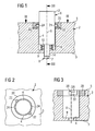
- a cylinder head arrangement ( Figure 1) comprises an injection valve 6 and a cylinder head 2.
- a first side 3 of the cylinder head 2 forms a wall of a combustion chamber if the cylinder head 2 is arranged in an internal combustion engine.
- a recess 4 of the cylinder head 2 extends from the first side 3 of the cylinder head 2 to a second side 5 of the cylinder head.
- the injection valve 6 is arranged in the cylinder head 2 of the internal combustion engine.
- the injection valve 6 comprises an injection nozzle 7 at an injector tip 8.
- the injection valve 6 further comprises a first axial section 12 and a second axial section 14 which are separated by a step 16 of the injection valve.
- the injection valve 6 is fixed into the recess 4 by a groove 22 of the cylinder head 2 which is formed in a plate 20 and which works together with a pin 24 of the injection valve 6.
- the pin 24 of the injection valve 6 and an injector body of the injection valve 6 may be made of one piece. Alternatively the pin 24 may be welded to the injection valve 6 or the pin 24 may be screwed into the injection valve 6.
- the injection valve 6 is plugged into the recess 4 of the cylinder head 2 from the second side 5 of the cylinder head 2.
- a spring 10 arranged at a step 9 of the recess 4. The spring 10 exerts a force on the injection valve 6 directed towards the second side 5 of the cylinder head 2.
- a groove 22 of the cylinder head 2 extends from the second side 2 of the cylinder head 2 towards the first side 3 of the cylinder head 2 ( Figure 2, Figure 3).
- the groove 22 of the cylinder head 2 further extends to a narrow part 29 of the groove 22 of the cylinder head 2 which extends perpendicularly to an axis X of the injection valve 6 and/or of the recess 4. From the narrow part 29 the groove 22 of the cylinder head 2 further extends directed towards the second side 5 of the cylinder head 2.
- the pin 24 of the injection valve 6 is introduced into the groove 22 of the cylinder head 2 at the second side 5 of the cylinder head 2 and the spring 10 is getting preloaded. If the pin 24 of the injection valve 6 is at the narrow part 29 of the groove 22 of the cylinder head 2, the injection valve 6 may be turned around the axis X. After the narrow part 29 of the groove 22 of the cylinder head 2 the pin 24 is in a position in which the spring 10 forces the injection valve 6, especially the pin 24 of the injection valve 6 towards a backstop 28 of the groove 22 of the cylinder head 2. So, the injection valve 6 is fixed in its position by a positive-fit and by a press-fit.
- the groove 22 of the cylinder head 2 and the corresponding pin 24 of the injection valve 6 may be formed in such a way that the injection valve 6 is fixed in the recess 4 only by a positive-fit.
- the narrow part 29 of the groove 22 of the cylinder head 2 comprises a smaller width than the corresponding pin 24 of the injection valve 6 the pin 24 of the injection valve 6 may be pressed through the narrow part 29 into backstop 28 of the groove 22 of the cylinder head 2.
- the pin 24 of the injection valve 6 and the backstop 28 of the groove 22 of the cylinder head 2 are formed and arranged in such a way that the pin 24 of the injection valve 6 fits exactly into the backstop 28 of the groove 22 of the cylinder head 2, then the injection valve 6 is fixed in its position only by the positive-fit.
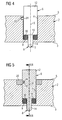
- the groove 22 is formed directly in the cylinder head 2 ( Figure 4). If the groove 22 is formed directly in the cylinder head 2, this may contribute to a proper stability of the groove 22 of the cylinder head 2.
- the injection valve 6 may comprise only one pin 24 and the cylinder head 2 may only comprise one groove 22 or the injection valve 6 may comprise further pins 24 and the cylinder head may comprise further grooves 22.
- the plate 20 comprises a pin 44 of the cylinder head 2.
- the pin 44 of the cylinder head 2 and/or the plate 20 and/or the cylinder head 2 may be made of one piece. If the pin 44 and/or respectively the plate 20 and/or respectively the cylinder head 2 are made of one piece, this may contribute to a good stability of the pin 44 of the cylinder head 2.
- the pin 44 and/or respectively the plate 20 may be welded to the cylinder head 2 or the pin 44 and/or respectively the plate 20 may be screwed into the cylinder head 2.
- the injection valve 6 may be assembled into the cylinder head 2 by introducing the pin 44 of the cylinder head 2 into the groove 42 of the injection valve 6 at the step 16.
- the groove 42 of the cylinder head 2 is formed in such a way that the rubber ring 30 is preloaded when the injection valve 6 is inserted to the recess 4 and when the injection valve 6 is turned around its axis X in such a way that the pin 44 of the cylinder head 2 is at a backstop 48 of the groove 42 of the injection valve 6. So, the injection valve 6 is fixed in its position by the positive-fit.
- the rubber ring 30 can be used instead of the spring 10 in every embodiment.
- every embodiment may comprise the plate 20 or not.
- every embodiment may comprise the pin 24 of the injection valve 6 and the groove 22 of the cylinder head 2 and/or the pin 44 of the cylinder head 2 and the groove 42 of the cylinder head.
- the injection valve 6 may be hold in the recess 4 by a positive-fit or by a combination of a positive-fit.
Landscapes
- Engineering & Computer Science (AREA)
- Chemical & Material Sciences (AREA)
- Combustion & Propulsion (AREA)
- Mechanical Engineering (AREA)
- General Engineering & Computer Science (AREA)
- Cylinder Crankcases Of Internal Combustion Engines (AREA)
- Fuel-Injection Apparatus (AREA)
Priority Applications (2)
| Application Number | Priority Date | Filing Date | Title |
|---|---|---|---|
| EP20050023667 EP1780404B1 (fr) | 2005-10-28 | 2005-10-28 | Injecteur, culasse et agencement de celle-ci pour un moteur à combustion interne |
| DE200560013972 DE602005013972D1 (de) | 2005-10-28 | 2005-10-28 | Einspritzventil, Zylinderkopf und Zylinderkopfanordnung für eine Brennkraftmaschine |
Applications Claiming Priority (1)
| Application Number | Priority Date | Filing Date | Title |
|---|---|---|---|
| EP20050023667 EP1780404B1 (fr) | 2005-10-28 | 2005-10-28 | Injecteur, culasse et agencement de celle-ci pour un moteur à combustion interne |
Publications (2)
| Publication Number | Publication Date |
|---|---|
| EP1780404A1 true EP1780404A1 (fr) | 2007-05-02 |
| EP1780404B1 EP1780404B1 (fr) | 2009-04-15 |
Family
ID=35520975
Family Applications (1)
| Application Number | Title | Priority Date | Filing Date |
|---|---|---|---|
| EP20050023667 Expired - Lifetime EP1780404B1 (fr) | 2005-10-28 | 2005-10-28 | Injecteur, culasse et agencement de celle-ci pour un moteur à combustion interne |
Country Status (2)
| Country | Link |
|---|---|
| EP (1) | EP1780404B1 (fr) |
| DE (1) | DE602005013972D1 (fr) |
Cited By (1)
| Publication number | Priority date | Publication date | Assignee | Title |
|---|---|---|---|---|
| EP2014909A3 (fr) * | 2007-07-11 | 2011-05-04 | Delphi Technologies, Inc. | Raccord d'injecteur de carburant à une rampe de carburant |
Citations (4)
| Publication number | Priority date | Publication date | Assignee | Title |
|---|---|---|---|---|
| US1970801A (en) * | 1932-04-26 | 1934-08-21 | Bosch Robert | Fuel injection nozzle for internal combustion engines |
| US20020073970A1 (en) * | 2000-12-18 | 2002-06-20 | Siemens Automotive Corporation | Hpdi injector and packaging |
| US20040194764A1 (en) * | 2002-07-26 | 2004-10-07 | Denso Corporation | Fuel supply apparatus having resilient injector-pressing member |
| DE10356856A1 (de) * | 2003-12-05 | 2005-07-07 | Siemens Ag | Injektor für die Kraftstoffeinspritzung mit einer Spannvorrichtung zum Einbau in einem Zylinderkopf einer Brennkraftmaschine sowie Spannvorrichtung |
-
2005
- 2005-10-28 DE DE200560013972 patent/DE602005013972D1/de not_active Expired - Lifetime
- 2005-10-28 EP EP20050023667 patent/EP1780404B1/fr not_active Expired - Lifetime
Patent Citations (4)
| Publication number | Priority date | Publication date | Assignee | Title |
|---|---|---|---|---|
| US1970801A (en) * | 1932-04-26 | 1934-08-21 | Bosch Robert | Fuel injection nozzle for internal combustion engines |
| US20020073970A1 (en) * | 2000-12-18 | 2002-06-20 | Siemens Automotive Corporation | Hpdi injector and packaging |
| US20040194764A1 (en) * | 2002-07-26 | 2004-10-07 | Denso Corporation | Fuel supply apparatus having resilient injector-pressing member |
| DE10356856A1 (de) * | 2003-12-05 | 2005-07-07 | Siemens Ag | Injektor für die Kraftstoffeinspritzung mit einer Spannvorrichtung zum Einbau in einem Zylinderkopf einer Brennkraftmaschine sowie Spannvorrichtung |
Cited By (1)
| Publication number | Priority date | Publication date | Assignee | Title |
|---|---|---|---|---|
| EP2014909A3 (fr) * | 2007-07-11 | 2011-05-04 | Delphi Technologies, Inc. | Raccord d'injecteur de carburant à une rampe de carburant |
Also Published As
| Publication number | Publication date |
|---|---|
| DE602005013972D1 (de) | 2009-05-28 |
| EP1780404B1 (fr) | 2009-04-15 |
Similar Documents
| Publication | Publication Date | Title |
|---|---|---|
| US7564175B2 (en) | Tubular spring for actuator, and method for assembling the tubular spring | |
| CN102016289B (zh) | 弹簧保持套筒 | |
| EP2221469A1 (fr) | Élément de fixation et ensemble d'injecteur de fluide | |
| EP2902616B1 (fr) | Dispositif de couplage | |
| KR102250932B1 (ko) | 연료 안내 컴포넌트, 연료 분사 밸브 및 연결 장치를 포함하는 연료 분사 시스템 | |
| JP4200008B2 (ja) | 固定装置 | |
| KR20150003758A (ko) | 하나의 연료 분배기 및 다수의 연료 분사 밸브를 구비한 장치 | |
| CN107690530B (zh) | 流体压力缸 | |
| KR20020087491A (ko) | 연료 분사 밸브용 밀봉 장치 | |
| EP2068023A1 (fr) | Agencement de couplage et ensemble de connexion | |
| JP2008542601A (ja) | 接続システム | |
| US20170138325A1 (en) | Fuel injector device having pin retainer | |
| US20170074223A1 (en) | Fuel injector mounting device and fuel rail | |
| EP1780404B1 (fr) | Injecteur, culasse et agencement de celle-ci pour un moteur à combustion interne | |
| JP2017127924A (ja) | 圧入装置 | |
| JP5654682B2 (ja) | 燃料、好適にディーゼル燃料を内燃機関へと供給するポンプユニット、及び、関連する組立方法 | |
| KR102079672B1 (ko) | 유체압 실린더 | |
| EP2077390B1 (fr) | Agencement de couplage et ensemble de connexion | |
| JP2006132437A (ja) | 燃料噴射弁取付構造 | |
| EP3009660B1 (fr) | Ensemble de soupape pourvu d'un élément de guidage et injecteur de fluide | |
| EP1862668A1 (fr) | Dispositif de couplage et assemblage de liaison | |
| JP6536366B2 (ja) | 燃料噴射装置 | |
| EP1884657B1 (fr) | Dispositif de fixation d'un injecteur de carburant sur une culasse de moteur à combustion interne | |
| EP1887215A1 (fr) | Dispositif de serrage et culasse | |
| US10309563B2 (en) | Drive unit, internal combustion engine, spacer element for a fluid line arrangement, and tool kit for mounting a spacer element |
Legal Events
| Date | Code | Title | Description |
|---|---|---|---|
| PUAI | Public reference made under article 153(3) epc to a published international application that has entered the european phase |
Free format text: ORIGINAL CODE: 0009012 |
|
| AK | Designated contracting states |
Kind code of ref document: A1 Designated state(s): AT BE BG CH CY CZ DE DK EE ES FI FR GB GR HU IE IS IT LI LT LU LV MC NL PL PT RO SE SI SK TR |
|
| AX | Request for extension of the european patent |
Extension state: AL BA HR MK YU |
|
| 17P | Request for examination filed |
Effective date: 20071022 |
|
| AKX | Designation fees paid |
Designated state(s): DE FR IT |
|
| 17Q | First examination report despatched |
Effective date: 20080410 |
|
| RAP1 | Party data changed (applicant data changed or rights of an application transferred) |
Owner name: CONTINENTAL AUTOMOTIVE GMBH |
|
| GRAP | Despatch of communication of intention to grant a patent |
Free format text: ORIGINAL CODE: EPIDOSNIGR1 |
|
| GRAP | Despatch of communication of intention to grant a patent |
Free format text: ORIGINAL CODE: EPIDOSNIGR1 |
|
| GRAS | Grant fee paid |
Free format text: ORIGINAL CODE: EPIDOSNIGR3 |
|
| GRAA | (expected) grant |
Free format text: ORIGINAL CODE: 0009210 |
|
| AK | Designated contracting states |
Kind code of ref document: B1 Designated state(s): DE FR IT |
|
| REF | Corresponds to: |
Ref document number: 602005013972 Country of ref document: DE Date of ref document: 20090528 Kind code of ref document: P |
|
| PLBE | No opposition filed within time limit |
Free format text: ORIGINAL CODE: 0009261 |
|
| STAA | Information on the status of an ep patent application or granted ep patent |
Free format text: STATUS: NO OPPOSITION FILED WITHIN TIME LIMIT |
|
| 26N | No opposition filed |
Effective date: 20100118 |
|
| REG | Reference to a national code |
Ref country code: FR Ref legal event code: PLFP Year of fee payment: 11 |
|
| REG | Reference to a national code |
Ref country code: FR Ref legal event code: PLFP Year of fee payment: 12 |
|
| REG | Reference to a national code |
Ref country code: FR Ref legal event code: PLFP Year of fee payment: 13 |
|
| REG | Reference to a national code |
Ref country code: FR Ref legal event code: PLFP Year of fee payment: 14 |
|
| PGFP | Annual fee paid to national office [announced via postgrant information from national office to epo] |
Ref country code: DE Payment date: 20181031 Year of fee payment: 14 |
|
| PGFP | Annual fee paid to national office [announced via postgrant information from national office to epo] |
Ref country code: FR Payment date: 20181022 Year of fee payment: 14 Ref country code: IT Payment date: 20181024 Year of fee payment: 14 |
|
| REG | Reference to a national code |
Ref country code: DE Ref legal event code: R119 Ref document number: 602005013972 Country of ref document: DE |
|
| PG25 | Lapsed in a contracting state [announced via postgrant information from national office to epo] |
Ref country code: DE Free format text: LAPSE BECAUSE OF NON-PAYMENT OF DUE FEES Effective date: 20200501 |
|
| PG25 | Lapsed in a contracting state [announced via postgrant information from national office to epo] |
Ref country code: IT Free format text: LAPSE BECAUSE OF NON-PAYMENT OF DUE FEES Effective date: 20191028 Ref country code: FR Free format text: LAPSE BECAUSE OF NON-PAYMENT OF DUE FEES Effective date: 20191031 |