EP3009660B1 - Ensemble de soupape pourvu d'un élément de guidage et injecteur de fluide - Google Patents
Ensemble de soupape pourvu d'un élément de guidage et injecteur de fluide Download PDFInfo
- Publication number
- EP3009660B1 EP3009660B1 EP14188752.1A EP14188752A EP3009660B1 EP 3009660 B1 EP3009660 B1 EP 3009660B1 EP 14188752 A EP14188752 A EP 14188752A EP 3009660 B1 EP3009660 B1 EP 3009660B1
- Authority
- EP
- European Patent Office
- Prior art keywords
- guiding element
- valve
- valve needle
- valve assembly
- needle
- Prior art date
- Legal status (The legal status is an assumption and is not a legal conclusion. Google has not performed a legal analysis and makes no representation as to the accuracy of the status listed.)
- Not-in-force
Links
Images


Classifications
-
- F—MECHANICAL ENGINEERING; LIGHTING; HEATING; WEAPONS; BLASTING
- F02—COMBUSTION ENGINES; HOT-GAS OR COMBUSTION-PRODUCT ENGINE PLANTS
- F02M—SUPPLYING COMBUSTION ENGINES IN GENERAL WITH COMBUSTIBLE MIXTURES OR CONSTITUENTS THEREOF
- F02M61/00—Fuel-injectors not provided for in groups F02M39/00 - F02M57/00 or F02M67/00
- F02M61/16—Details not provided for in, or of interest apart from, the apparatus of groups F02M61/02 - F02M61/14
- F02M61/20—Closing valves mechanically, e.g. arrangements of springs or weights or permanent magnets; Damping of valve lift
-
- F—MECHANICAL ENGINEERING; LIGHTING; HEATING; WEAPONS; BLASTING
- F02—COMBUSTION ENGINES; HOT-GAS OR COMBUSTION-PRODUCT ENGINE PLANTS
- F02M—SUPPLYING COMBUSTION ENGINES IN GENERAL WITH COMBUSTIBLE MIXTURES OR CONSTITUENTS THEREOF
- F02M51/00—Fuel-injection apparatus characterised by being operated electrically
- F02M51/06—Injectors peculiar thereto with means directly operating the valve needle
- F02M51/061—Injectors peculiar thereto with means directly operating the valve needle using electromagnetic operating means
- F02M51/0625—Injectors peculiar thereto with means directly operating the valve needle using electromagnetic operating means characterised by arrangement of mobile armatures
- F02M51/0635—Injectors peculiar thereto with means directly operating the valve needle using electromagnetic operating means characterised by arrangement of mobile armatures having a plate-shaped or undulated armature not entering the winding
- F02M51/0642—Injectors peculiar thereto with means directly operating the valve needle using electromagnetic operating means characterised by arrangement of mobile armatures having a plate-shaped or undulated armature not entering the winding the armature having a valve attached thereto
- F02M51/0653—Injectors peculiar thereto with means directly operating the valve needle using electromagnetic operating means characterised by arrangement of mobile armatures having a plate-shaped or undulated armature not entering the winding the armature having a valve attached thereto the valve being an elongated body, e.g. a needle valve
-
- F—MECHANICAL ENGINEERING; LIGHTING; HEATING; WEAPONS; BLASTING
- F02—COMBUSTION ENGINES; HOT-GAS OR COMBUSTION-PRODUCT ENGINE PLANTS
- F02M—SUPPLYING COMBUSTION ENGINES IN GENERAL WITH COMBUSTIBLE MIXTURES OR CONSTITUENTS THEREOF
- F02M61/00—Fuel-injectors not provided for in groups F02M39/00 - F02M57/00 or F02M67/00
- F02M61/04—Fuel-injectors not provided for in groups F02M39/00 - F02M57/00 or F02M67/00 having valves, e.g. having a plurality of valves in series
- F02M61/08—Fuel-injectors not provided for in groups F02M39/00 - F02M57/00 or F02M67/00 having valves, e.g. having a plurality of valves in series the valves opening in direction of fuel flow
-
- F—MECHANICAL ENGINEERING; LIGHTING; HEATING; WEAPONS; BLASTING
- F02—COMBUSTION ENGINES; HOT-GAS OR COMBUSTION-PRODUCT ENGINE PLANTS
- F02M—SUPPLYING COMBUSTION ENGINES IN GENERAL WITH COMBUSTIBLE MIXTURES OR CONSTITUENTS THEREOF
- F02M61/00—Fuel-injectors not provided for in groups F02M39/00 - F02M57/00 or F02M67/00
- F02M61/04—Fuel-injectors not provided for in groups F02M39/00 - F02M57/00 or F02M67/00 having valves, e.g. having a plurality of valves in series
- F02M61/10—Other injectors with elongated valve bodies, i.e. of needle-valve type
- F02M61/12—Other injectors with elongated valve bodies, i.e. of needle-valve type characterised by the provision of guiding or centring means for valve bodies
-
- F—MECHANICAL ENGINEERING; LIGHTING; HEATING; WEAPONS; BLASTING
- F02—COMBUSTION ENGINES; HOT-GAS OR COMBUSTION-PRODUCT ENGINE PLANTS
- F02M—SUPPLYING COMBUSTION ENGINES IN GENERAL WITH COMBUSTIBLE MIXTURES OR CONSTITUENTS THEREOF
- F02M63/00—Other fuel-injection apparatus having pertinent characteristics not provided for in groups F02M39/00 - F02M57/00 or F02M67/00; Details, component parts, or accessories of fuel-injection apparatus, not provided for in, or of interest apart from, the apparatus of groups F02M39/00 - F02M61/00 or F02M67/00; Combination of fuel pump with other devices, e.g. lubricating oil pump
- F02M63/001—Fuel-injection apparatus having injection valves held closed mechanically, e.g. by springs, and opened by a cyclically-operated mechanism for a time
-
- F—MECHANICAL ENGINEERING; LIGHTING; HEATING; WEAPONS; BLASTING
- F16—ENGINEERING ELEMENTS AND UNITS; GENERAL MEASURES FOR PRODUCING AND MAINTAINING EFFECTIVE FUNCTIONING OF MACHINES OR INSTALLATIONS; THERMAL INSULATION IN GENERAL
- F16F—SPRINGS; SHOCK-ABSORBERS; MEANS FOR DAMPING VIBRATION
- F16F1/00—Springs
- F16F1/02—Springs made of steel or other material having low internal friction; Wound, torsion, leaf, cup, ring or the like springs, the material of the spring not being relevant
- F16F1/025—Springs made of steel or other material having low internal friction; Wound, torsion, leaf, cup, ring or the like springs, the material of the spring not being relevant characterised by having a particular shape
- F16F1/028—Springs made of steel or other material having low internal friction; Wound, torsion, leaf, cup, ring or the like springs, the material of the spring not being relevant characterised by having a particular shape cylindrical, with radial openings
-
- F—MECHANICAL ENGINEERING; LIGHTING; HEATING; WEAPONS; BLASTING
- F16—ENGINEERING ELEMENTS AND UNITS; GENERAL MEASURES FOR PRODUCING AND MAINTAINING EFFECTIVE FUNCTIONING OF MACHINES OR INSTALLATIONS; THERMAL INSULATION IN GENERAL
- F16K—VALVES; TAPS; COCKS; ACTUATING-FLOATS; DEVICES FOR VENTING OR AERATING
- F16K1/00—Lift valves or globe valves, i.e. cut-off apparatus with closure members having at least a component of their opening and closing motion perpendicular to the closing faces
- F16K1/32—Details
- F16K1/54—Arrangements for modifying the way in which the rate of flow varies during the actuation of the valve
-
- F—MECHANICAL ENGINEERING; LIGHTING; HEATING; WEAPONS; BLASTING
- F16—ENGINEERING ELEMENTS AND UNITS; GENERAL MEASURES FOR PRODUCING AND MAINTAINING EFFECTIVE FUNCTIONING OF MACHINES OR INSTALLATIONS; THERMAL INSULATION IN GENERAL
- F16K—VALVES; TAPS; COCKS; ACTUATING-FLOATS; DEVICES FOR VENTING OR AERATING
- F16K15/00—Check valves
- F16K15/18—Check valves with actuating mechanism; Combined check valves and actuated valves
-
- F—MECHANICAL ENGINEERING; LIGHTING; HEATING; WEAPONS; BLASTING
- F16—ENGINEERING ELEMENTS AND UNITS; GENERAL MEASURES FOR PRODUCING AND MAINTAINING EFFECTIVE FUNCTIONING OF MACHINES OR INSTALLATIONS; THERMAL INSULATION IN GENERAL
- F16K—VALVES; TAPS; COCKS; ACTUATING-FLOATS; DEVICES FOR VENTING OR AERATING
- F16K31/00—Actuating devices; Operating means; Releasing devices
- F16K31/02—Actuating devices; Operating means; Releasing devices electric; magnetic
- F16K31/06—Actuating devices; Operating means; Releasing devices electric; magnetic using a magnet, e.g. diaphragm valves, cutting off by means of a liquid
- F16K31/0644—One-way valve
- F16K31/0655—Lift valves
-
- F—MECHANICAL ENGINEERING; LIGHTING; HEATING; WEAPONS; BLASTING
- F02—COMBUSTION ENGINES; HOT-GAS OR COMBUSTION-PRODUCT ENGINE PLANTS
- F02M—SUPPLYING COMBUSTION ENGINES IN GENERAL WITH COMBUSTIBLE MIXTURES OR CONSTITUENTS THEREOF
- F02M2200/00—Details of fuel-injection apparatus, not otherwise provided for
- F02M2200/26—Fuel-injection apparatus with elastically deformable elements other than coil springs
-
- F—MECHANICAL ENGINEERING; LIGHTING; HEATING; WEAPONS; BLASTING
- F02—COMBUSTION ENGINES; HOT-GAS OR COMBUSTION-PRODUCT ENGINE PLANTS
- F02M—SUPPLYING COMBUSTION ENGINES IN GENERAL WITH COMBUSTIBLE MIXTURES OR CONSTITUENTS THEREOF
- F02M2200/00—Details of fuel-injection apparatus, not otherwise provided for
- F02M2200/80—Fuel injection apparatus manufacture, repair or assembly
- F02M2200/8069—Fuel injection apparatus manufacture, repair or assembly involving removal of material from the fuel apparatus, e.g. by punching, hydro-erosion or mechanical operation
-
- F—MECHANICAL ENGINEERING; LIGHTING; HEATING; WEAPONS; BLASTING
- F02—COMBUSTION ENGINES; HOT-GAS OR COMBUSTION-PRODUCT ENGINE PLANTS
- F02M—SUPPLYING COMBUSTION ENGINES IN GENERAL WITH COMBUSTIBLE MIXTURES OR CONSTITUENTS THEREOF
- F02M2200/00—Details of fuel-injection apparatus, not otherwise provided for
- F02M2200/90—Selection of particular materials
- F02M2200/9053—Metals
Definitions
- the valve assembly has a valve body and a valve needle.
- the valve body has a longitudinal axis and comprises a cavity with a valve seat.
- the cavity is limited by a wall of the valve body.
- the valve seat is in particular comprised by a surface of the wall which defines the cavity.
- the valve needle is received in the cavity.
- the injector further comprises an actuator assembly which is operable to exert a force for influencing a position of the valve needle.
- the actuator assembly is operable to displace the valve needle away from the closing position.
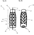
- the outer shape of the first guiding element is in particular defined by an outer diameter of the first guiding element. That the first guiding element is "bottle shaped" means in particular, that it has a smooth and curved outer shape - i.e. in particular without kinks or steps - that gradually reduces its cross section in the course from the fixation section to the bottle neck section which is in particular a second axial end section of the first guiding element, remote from the first axial end section where it is coupled to the wall of the valve body.
- the first guiding element is preferably in the basic shape of a hollow body of revolution.
- the first guiding element has in particular an outer diameter which decreases gradually from the fixation section to the bottle neck section.
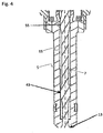
- the valve needle 7 is received in the cavity 11 and axially movable relative to the valve body 5.
- the valve needle 7 is operable to prevent an injection of fluid in a closing position, in which the valve needle 7 is seated on the valve seat 13, from the cavity 11 to external to the injector 1, for example into a combustion chamber.
- the valve needle 7 is further operable to enable the injection of fluid when it is apart from the closing position.
Landscapes
- Engineering & Computer Science (AREA)
- General Engineering & Computer Science (AREA)
- Mechanical Engineering (AREA)
- Chemical & Material Sciences (AREA)
- Combustion & Propulsion (AREA)
- Physics & Mathematics (AREA)
- Electromagnetism (AREA)
- Fuel-Injection Apparatus (AREA)
- Infusion, Injection, And Reservoir Apparatuses (AREA)
- Nozzles (AREA)
- Lift Valve (AREA)
Claims (15)
- Ensemble soupape (3) pour un injecteur (1) de fluide, l'ensemble soupape (3) comprenant un corps (5) de soupape et un pointeau (7) de soupape, le corps (5) de soupape comportant un axe longitudinal (9) et comprenant une cavité (11) avec un siège (13) de soupape, la cavité (11) étant limitée par une paroi (15) du corps (5) de soupape, le pointeau (7) de soupape étant reçu dans la cavité (11), la cavité (11) et le pointeau (7) de soupape entrant en interaction pour empêcher une injection de fluide de la cavité (11) à l'extérieur de l'injecteur (1) quand le pointeau (7) de soupape est en position de fermeture, dans laquelle le pointeau (7) de soupape s'appuie sur le siège (13) de soupape, et pour permettre l'injection de fluide quand le pointeau (7) de soupape est séparé de sa position de fermeture, et
un premier élément de guidage (19) pour guider axialement le pointeau (7) de soupape,
dans lequel le premier élément de guidage (19) est configuré et agencé de telle sorte qu'un déplacement axial du pointeau (7) de soupape l'éloignant de la position de fermeture entraîne un élargissement de la forme extérieure du premier élément de guidage (19) au moins dans une section (25) de fixation pour l'appuyer contre la paroi (15) du corps (5) de soupape,
au moyen du fait que le premier élément de guidage- est en forme de bouteille et est déformable axialement au moins en partie,- est accouplé à demeure au pointeau (7) de soupape dans une section (21) de goulot du premier élément de guidage (19), et est accouplé à la paroi (15) du corps (5) de soupape dans une section terminale axiale (23) du premier élément de guidage (19) distant de la section (21) de goulot. - Ensemble soupape (3) selon la revendication 1, dans lequel le premier élément de guidage (19) comprend un manchon (27) de ressort ayant la forme de bouteille et étant accouplé à demeure au pointeau (7) de soupape dans la section (21) de goulot.
- Ensemble soupape (3) selon la revendication 2, dans lequel le premier élément de guidage (19) comprend un anneau de fixation (29) qui est disposé radialement entre le pointeau (7) de soupape et le manchon (27) de ressort pour accoupler à demeure le manchon (27) de ressort au pointeau (7) de soupape dans la section (21) de goulot.
- Ensemble soupape (3) selon l'une quelconque des revendications 1 à 3, dans lequel la paroi (15) du corps (5) de soupape comprend un siège guide (31) pour limiter axialement un déplacement axial du premier élément de guidage (19) par rapport au corps (5) de soupape, dans lequel le premier élément de guidage (19) est utilisable pour reposer sur le siège guide (31) par sa section terminale axiale (23) de façon qu'un déplacement axial du pointeau (7) de soupape l'éloignant de la position de fermeture entraîne une déformation axiale d'au moins une partie du premier élément de guidage (19), faisant s'élargir la forme extérieure du premier élément de guidage (19).
- Ensemble soupape (3) selon l'une quelconque des revendications 1 à 4, dans lequel le premier élément de guidage (19) est au moins en partie déformable élastiquement.
- Ensemble soupape (3) selon l'une quelconque des revendications 1 à 5, dans lequel le premier élément de guidage (19) est au moins en partie fait de métal.
- Ensemble soupape (3) selon l'une quelconque des revendications 1 à 6, dans lequel le premier élément de guidage (19) comprend une pluralité de fentes (33).
- Ensemble soupape (3) selon la revendication 7, dans lequel la forme de chacune des fentes (33) s'étend transversalement par rapport à l'axe longitudinal (9) quand le premier élément de guidage (19) est dans un état non déformé.
- Ensemble soupape (3) selon la revendication 8, dans lequel l'extension latérale de la forme de chacune des fentes (33) est comprise entre 2 mm et 7 mm quand le premier élément de guidage (19) est dans un état non déformé.
- Ensemble soupape (3) selon l'une quelconque des revendications 7 à 9, dans lequel l'intervalle axial qui sépare l'une de l'autre les fentes (33) est compris entre 0,2 mm et 0,8 mm quand le premier élément de guidage (19) est dans un état non déformé.
- Ensemble soupape (3) selon l'une quelconque des revendications 7 à 10, dans lequel l'intervalle latéral qui sépare l'une de l'autre les fentes (33) est compris entre 0,4 mm et 1 mm quand le premier élément de guidage (19) est dans un état non déformé.
- Ensemble soupape (3) selon l'une quelconque des revendications 1 à 11, dans lequel la largeur (39) du premier élément de guidage (19) varie axialement de la section (21) de goulot vers la section terminale axiale (23), en particulier de 2,5 mm au niveau de la section (21) de goulot à 7 mm au niveau de la section terminale axiale (23).
- Ensemble soupape (3) selon l'une quelconque des revendications 1 à 12, dans lequel l'extension axiale (41) du premier élément de guidage (19) est comprise entre 10 mm et 18 mm et est en particulier de 15 mm.
- Ensemble soupape (3) selon l'une quelconque des revendications 1 à 10, dans lequel l'épaisseur (43) de paroi du premier élément de guidage (19) est comprise entre 0,3 mm et 0,9 mm et est en particulier de 0,5 mm.
- Injecteur (1) de fluide comprenant un ensemble soupape (3) selon l'une quelconque des revendications 1 à 14 et un ensemble actionneur (17), qui sert à exercer une force pour éloigner le pointeau (7) de soupape de la position de fermeture, dans lequel le premier élément de guidage (19) produit une force pour solliciter le pointeau (7) de soupape vers la position de fermeture, et dans lequel l'ensemble actionneur (17) sert à déplacer le pointeau (7) de soupape à l'encontre de la sollicitation du premier élément de guidage (19).
Priority Applications (3)
| Application Number | Priority Date | Filing Date | Title |
|---|---|---|---|
| EP14188752.1A EP3009660B1 (fr) | 2014-10-14 | 2014-10-14 | Ensemble de soupape pourvu d'un élément de guidage et injecteur de fluide |
| US14/827,123 US9624885B2 (en) | 2014-10-14 | 2015-08-14 | Valve assembly with a guiding element and fluid injector |
| CN201510659556.6A CN105508108B (zh) | 2014-10-14 | 2015-10-14 | 设有导引元件的阀组件以及流体喷射器 |
Applications Claiming Priority (1)
| Application Number | Priority Date | Filing Date | Title |
|---|---|---|---|
| EP14188752.1A EP3009660B1 (fr) | 2014-10-14 | 2014-10-14 | Ensemble de soupape pourvu d'un élément de guidage et injecteur de fluide |
Publications (2)
| Publication Number | Publication Date |
|---|---|
| EP3009660A1 EP3009660A1 (fr) | 2016-04-20 |
| EP3009660B1 true EP3009660B1 (fr) | 2017-05-03 |
Family
ID=51690290
Family Applications (1)
| Application Number | Title | Priority Date | Filing Date |
|---|---|---|---|
| EP14188752.1A Not-in-force EP3009660B1 (fr) | 2014-10-14 | 2014-10-14 | Ensemble de soupape pourvu d'un élément de guidage et injecteur de fluide |
Country Status (3)
| Country | Link |
|---|---|
| US (1) | US9624885B2 (fr) |
| EP (1) | EP3009660B1 (fr) |
| CN (1) | CN105508108B (fr) |
Families Citing this family (1)
| Publication number | Priority date | Publication date | Assignee | Title |
|---|---|---|---|---|
| DE102020121777A1 (de) * | 2020-08-19 | 2022-02-24 | Vermes Microdispensing GmbH | Ventilstößelstange |
Family Cites Families (15)
| Publication number | Priority date | Publication date | Assignee | Title |
|---|---|---|---|---|
| US2756106A (en) * | 1954-03-18 | 1956-07-24 | Schenk Rudolf | Fuel injection valve |
| DE1053244B (de) * | 1955-10-28 | 1959-03-19 | Bosch Arma Corp | Kraftstoff-Einspritzduese |
| US5299346A (en) | 1993-02-24 | 1994-04-05 | Siemens Automotive L.P. | Fuel injector upper needle guide burnishing and alignment tool |
| DE10032517A1 (de) | 2000-07-05 | 2002-01-24 | Bosch Gmbh Robert | Injektor mit Steuerteilführung |
| DE10213382A1 (de) * | 2002-03-26 | 2003-10-16 | Bosch Gmbh Robert | Kraftstoffeinspritzventil |
| DE10259802A1 (de) * | 2002-12-19 | 2004-07-01 | Robert Bosch Gmbh | Brennstoffeinspritzventil |
| EP1469187B1 (fr) * | 2003-04-16 | 2006-10-04 | Siemens Aktiengesellschaft | Ensemble de soupape a pointeau et procédé pour le réaliser |
| DE10319600A1 (de) | 2003-05-02 | 2004-11-18 | Robert Bosch Gmbh | Aktoreinheit für ein piezogesteuertes Kraftstoffeinspritzventil |
| WO2005080786A1 (fr) | 2004-02-11 | 2005-09-01 | Siemens Aktiengesellschaft | Element de contact pour le pointeau de la soupape d'un injecteur de moteurs a combustion interne |
| DE102004022619A1 (de) * | 2004-05-07 | 2005-12-08 | Robert Bosch Gmbh | Rohrfeder |
| EP1808596A1 (fr) * | 2006-01-12 | 2007-07-18 | Siemens Aktiengesellschaft | Assemblage de soupape pour un injecteur et l'injecteur |
| EP2282043B1 (fr) * | 2009-07-02 | 2013-04-17 | Continental Automotive GmbH | Injecteur de fluide et procédé et appareil pour faire fonctionner l'injecteur de fluide |
| US20110073071A1 (en) * | 2009-09-30 | 2011-03-31 | Woodward Governor Company | Internally Nested Variable-Area Fuel Nozzle |
| EP2436910B1 (fr) * | 2010-10-01 | 2017-05-03 | Continental Automotive GmbH | Ensemble de soupape pour soupape d'injection et soupape d'injection |
| EP2527637B1 (fr) * | 2011-05-23 | 2014-10-08 | Continental Automotive GmbH | Injecteur pour injection de fluides |
-
2014
- 2014-10-14 EP EP14188752.1A patent/EP3009660B1/fr not_active Not-in-force
-
2015
- 2015-08-14 US US14/827,123 patent/US9624885B2/en not_active Expired - Fee Related
- 2015-10-14 CN CN201510659556.6A patent/CN105508108B/zh not_active Expired - Fee Related
Also Published As
| Publication number | Publication date |
|---|---|
| CN105508108B (zh) | 2018-03-30 |
| CN105508108A (zh) | 2016-04-20 |
| US9624885B2 (en) | 2017-04-18 |
| EP3009660A1 (fr) | 2016-04-20 |
| US20160102639A1 (en) | 2016-04-14 |
Similar Documents
| Publication | Publication Date | Title |
|---|---|---|
| US7891586B2 (en) | Fuel injection valve for internal combustion engines | |
| EP0906508B1 (fr) | Injecteur de carburant pour moteur a combustion interne | |
| EP3155305B1 (fr) | Structure de raccordement de tuyau | |
| US9709010B2 (en) | Fuel injection valve | |
| CN107850021A (zh) | 燃料喷射装置 | |
| US9822749B2 (en) | Fuel injector | |
| KR102274062B1 (ko) | 연료 인젝터용 노즐 조립체 및 연료 인젝터 | |
| MX2010008306A (es) | Ensamblaje de valvula y metodo de ensamble. | |
| EP3009660B1 (fr) | Ensemble de soupape pourvu d'un élément de guidage et injecteur de fluide | |
| KR20150118918A (ko) | 밸브 바디 및 밸브 볼을 포함하는 배출 밸브를 구비한 고압 연료 펌프 | |
| EP1467086A1 (fr) | Soupape d'injection de carburant munie de deux manchons de réglage et procédé pour régler la prétension du ressort d'une soupape d'injection à ressort | |
| JP2011506814A (ja) | 燃料インジェクタアッセンブリの構成要素を整合し、プレストレスを加えるための装置 | |
| JP2001510530A (ja) | 内燃機関のための燃料噴射弁 | |
| US11092125B2 (en) | Valve for metering a fluid, in particular, a fuel injector | |
| KR100791043B1 (ko) | 내연기관용 연료분사밸브 및 그 조정핀을 원하는 위치에 위치시키고 고정하기 위한 방법 | |
| CN108138734B (zh) | 用于内燃机的流体喷射装置 | |
| JP6260316B2 (ja) | 燃料噴射弁 | |
| KR20160068914A (ko) | 연료 분사기 및 연료 분사 시스템 | |
| KR102071151B1 (ko) | 연소 엔진용 인젝터 | |
| EP2218903B1 (fr) | Procédé de fabrication d'une servovalve d'injecteur de carburant | |
| KR102786032B1 (ko) | 유체 계량 밸브, 특히 연료 분사 밸브 | |
| US20190162144A1 (en) | Method for manufacturing an injector for injecting fuel | |
| EP3156641A1 (fr) | Injecteur pour injection de fluides | |
| EP3359803B1 (fr) | Ensemble de soupape pour soupape d'injection, une telle soupape et procédé pour assembler ladite soupape | |
| US20170260949A1 (en) | Nozzle needle for a fuel injection device, and fuel injection device |
Legal Events
| Date | Code | Title | Description |
|---|---|---|---|
| PUAI | Public reference made under article 153(3) epc to a published international application that has entered the european phase |
Free format text: ORIGINAL CODE: 0009012 |
|
| AK | Designated contracting states |
Kind code of ref document: A1 Designated state(s): AL AT BE BG CH CY CZ DE DK EE ES FI FR GB GR HR HU IE IS IT LI LT LU LV MC MK MT NL NO PL PT RO RS SE SI SK SM TR |
|
| AX | Request for extension of the european patent |
Extension state: BA ME |
|
| GRAP | Despatch of communication of intention to grant a patent |
Free format text: ORIGINAL CODE: EPIDOSNIGR1 |
|
| 17P | Request for examination filed |
Effective date: 20161020 |
|
| RBV | Designated contracting states (corrected) |
Designated state(s): AL AT BE BG CH CY CZ DE DK EE ES FI FR GB GR HR HU IE IS IT LI LT LU LV MC MK MT NL NO PL PT RO RS SE SI SK SM TR |
|
| INTG | Intention to grant announced |
Effective date: 20161124 |
|
| GRAS | Grant fee paid |
Free format text: ORIGINAL CODE: EPIDOSNIGR3 |
|
| GRAA | (expected) grant |
Free format text: ORIGINAL CODE: 0009210 |
|
| AK | Designated contracting states |
Kind code of ref document: B1 Designated state(s): AL AT BE BG CH CY CZ DE DK EE ES FI FR GB GR HR HU IE IS IT LI LT LU LV MC MK MT NL NO PL PT RO RS SE SI SK SM TR |
|
| REG | Reference to a national code |
Ref country code: GB Ref legal event code: FG4D |
|
| REG | Reference to a national code |
Ref country code: AT Ref legal event code: REF Ref document number: 890291 Country of ref document: AT Kind code of ref document: T Effective date: 20170515 Ref country code: CH Ref legal event code: EP |
|
| REG | Reference to a national code |
Ref country code: IE Ref legal event code: FG4D |
|
| REG | Reference to a national code |
Ref country code: DE Ref legal event code: R096 Ref document number: 602014009237 Country of ref document: DE |
|
| REG | Reference to a national code |
Ref country code: NL Ref legal event code: MP Effective date: 20170503 |
|
| REG | Reference to a national code |
Ref country code: AT Ref legal event code: MK05 Ref document number: 890291 Country of ref document: AT Kind code of ref document: T Effective date: 20170503 |
|
| REG | Reference to a national code |
Ref country code: LT Ref legal event code: MG4D |
|
| PG25 | Lapsed in a contracting state [announced via postgrant information from national office to epo] |
Ref country code: NO Free format text: LAPSE BECAUSE OF FAILURE TO SUBMIT A TRANSLATION OF THE DESCRIPTION OR TO PAY THE FEE WITHIN THE PRESCRIBED TIME-LIMIT Effective date: 20170803 Ref country code: FI Free format text: LAPSE BECAUSE OF FAILURE TO SUBMIT A TRANSLATION OF THE DESCRIPTION OR TO PAY THE FEE WITHIN THE PRESCRIBED TIME-LIMIT Effective date: 20170503 Ref country code: AT Free format text: LAPSE BECAUSE OF FAILURE TO SUBMIT A TRANSLATION OF THE DESCRIPTION OR TO PAY THE FEE WITHIN THE PRESCRIBED TIME-LIMIT Effective date: 20170503 Ref country code: LT Free format text: LAPSE BECAUSE OF FAILURE TO SUBMIT A TRANSLATION OF THE DESCRIPTION OR TO PAY THE FEE WITHIN THE PRESCRIBED TIME-LIMIT Effective date: 20170503 Ref country code: GR Free format text: LAPSE BECAUSE OF FAILURE TO SUBMIT A TRANSLATION OF THE DESCRIPTION OR TO PAY THE FEE WITHIN THE PRESCRIBED TIME-LIMIT Effective date: 20170804 Ref country code: HR Free format text: LAPSE BECAUSE OF FAILURE TO SUBMIT A TRANSLATION OF THE DESCRIPTION OR TO PAY THE FEE WITHIN THE PRESCRIBED TIME-LIMIT Effective date: 20170503 Ref country code: ES Free format text: LAPSE BECAUSE OF FAILURE TO SUBMIT A TRANSLATION OF THE DESCRIPTION OR TO PAY THE FEE WITHIN THE PRESCRIBED TIME-LIMIT Effective date: 20170503 |
|
| PG25 | Lapsed in a contracting state [announced via postgrant information from national office to epo] |
Ref country code: PL Free format text: LAPSE BECAUSE OF FAILURE TO SUBMIT A TRANSLATION OF THE DESCRIPTION OR TO PAY THE FEE WITHIN THE PRESCRIBED TIME-LIMIT Effective date: 20170503 Ref country code: BG Free format text: LAPSE BECAUSE OF FAILURE TO SUBMIT A TRANSLATION OF THE DESCRIPTION OR TO PAY THE FEE WITHIN THE PRESCRIBED TIME-LIMIT Effective date: 20170803 Ref country code: IS Free format text: LAPSE BECAUSE OF FAILURE TO SUBMIT A TRANSLATION OF THE DESCRIPTION OR TO PAY THE FEE WITHIN THE PRESCRIBED TIME-LIMIT Effective date: 20170903 Ref country code: LV Free format text: LAPSE BECAUSE OF FAILURE TO SUBMIT A TRANSLATION OF THE DESCRIPTION OR TO PAY THE FEE WITHIN THE PRESCRIBED TIME-LIMIT Effective date: 20170503 Ref country code: RS Free format text: LAPSE BECAUSE OF FAILURE TO SUBMIT A TRANSLATION OF THE DESCRIPTION OR TO PAY THE FEE WITHIN THE PRESCRIBED TIME-LIMIT Effective date: 20170503 Ref country code: NL Free format text: LAPSE BECAUSE OF FAILURE TO SUBMIT A TRANSLATION OF THE DESCRIPTION OR TO PAY THE FEE WITHIN THE PRESCRIBED TIME-LIMIT Effective date: 20170503 Ref country code: SE Free format text: LAPSE BECAUSE OF FAILURE TO SUBMIT A TRANSLATION OF THE DESCRIPTION OR TO PAY THE FEE WITHIN THE PRESCRIBED TIME-LIMIT Effective date: 20170503 |
|
| PG25 | Lapsed in a contracting state [announced via postgrant information from national office to epo] |
Ref country code: CZ Free format text: LAPSE BECAUSE OF FAILURE TO SUBMIT A TRANSLATION OF THE DESCRIPTION OR TO PAY THE FEE WITHIN THE PRESCRIBED TIME-LIMIT Effective date: 20170503 Ref country code: EE Free format text: LAPSE BECAUSE OF FAILURE TO SUBMIT A TRANSLATION OF THE DESCRIPTION OR TO PAY THE FEE WITHIN THE PRESCRIBED TIME-LIMIT Effective date: 20170503 Ref country code: SK Free format text: LAPSE BECAUSE OF FAILURE TO SUBMIT A TRANSLATION OF THE DESCRIPTION OR TO PAY THE FEE WITHIN THE PRESCRIBED TIME-LIMIT Effective date: 20170503 Ref country code: RO Free format text: LAPSE BECAUSE OF FAILURE TO SUBMIT A TRANSLATION OF THE DESCRIPTION OR TO PAY THE FEE WITHIN THE PRESCRIBED TIME-LIMIT Effective date: 20170503 Ref country code: DK Free format text: LAPSE BECAUSE OF FAILURE TO SUBMIT A TRANSLATION OF THE DESCRIPTION OR TO PAY THE FEE WITHIN THE PRESCRIBED TIME-LIMIT Effective date: 20170503 |
|
| REG | Reference to a national code |
Ref country code: DE Ref legal event code: R097 Ref document number: 602014009237 Country of ref document: DE |
|
| PG25 | Lapsed in a contracting state [announced via postgrant information from national office to epo] |
Ref country code: SM Free format text: LAPSE BECAUSE OF FAILURE TO SUBMIT A TRANSLATION OF THE DESCRIPTION OR TO PAY THE FEE WITHIN THE PRESCRIBED TIME-LIMIT Effective date: 20170503 |
|
| PLBE | No opposition filed within time limit |
Free format text: ORIGINAL CODE: 0009261 |
|
| STAA | Information on the status of an ep patent application or granted ep patent |
Free format text: STATUS: NO OPPOSITION FILED WITHIN TIME LIMIT |
|
| 26N | No opposition filed |
Effective date: 20180206 |
|
| PG25 | Lapsed in a contracting state [announced via postgrant information from national office to epo] |
Ref country code: SI Free format text: LAPSE BECAUSE OF FAILURE TO SUBMIT A TRANSLATION OF THE DESCRIPTION OR TO PAY THE FEE WITHIN THE PRESCRIBED TIME-LIMIT Effective date: 20170503 Ref country code: MC Free format text: LAPSE BECAUSE OF FAILURE TO SUBMIT A TRANSLATION OF THE DESCRIPTION OR TO PAY THE FEE WITHIN THE PRESCRIBED TIME-LIMIT Effective date: 20170503 |
|
| REG | Reference to a national code |
Ref country code: CH Ref legal event code: PL |
|
| REG | Reference to a national code |
Ref country code: IE Ref legal event code: MM4A |
|
| REG | Reference to a national code |
Ref country code: FR Ref legal event code: ST Effective date: 20180629 |
|
| PG25 | Lapsed in a contracting state [announced via postgrant information from national office to epo] |
Ref country code: LI Free format text: LAPSE BECAUSE OF NON-PAYMENT OF DUE FEES Effective date: 20171031 Ref country code: LU Free format text: LAPSE BECAUSE OF NON-PAYMENT OF DUE FEES Effective date: 20171014 Ref country code: CH Free format text: LAPSE BECAUSE OF NON-PAYMENT OF DUE FEES Effective date: 20171031 |
|
| REG | Reference to a national code |
Ref country code: BE Ref legal event code: MM Effective date: 20171031 |
|
| PG25 | Lapsed in a contracting state [announced via postgrant information from national office to epo] |
Ref country code: FR Free format text: LAPSE BECAUSE OF NON-PAYMENT OF DUE FEES Effective date: 20171031 Ref country code: BE Free format text: LAPSE BECAUSE OF NON-PAYMENT OF DUE FEES Effective date: 20171031 |
|
| PG25 | Lapsed in a contracting state [announced via postgrant information from national office to epo] |
Ref country code: MT Free format text: LAPSE BECAUSE OF NON-PAYMENT OF DUE FEES Effective date: 20171014 |
|
| PG25 | Lapsed in a contracting state [announced via postgrant information from national office to epo] |
Ref country code: IE Free format text: LAPSE BECAUSE OF NON-PAYMENT OF DUE FEES Effective date: 20171014 |
|
| PG25 | Lapsed in a contracting state [announced via postgrant information from national office to epo] |
Ref country code: HU Free format text: LAPSE BECAUSE OF FAILURE TO SUBMIT A TRANSLATION OF THE DESCRIPTION OR TO PAY THE FEE WITHIN THE PRESCRIBED TIME-LIMIT; INVALID AB INITIO Effective date: 20141014 |
|
| PG25 | Lapsed in a contracting state [announced via postgrant information from national office to epo] |
Ref country code: CY Free format text: LAPSE BECAUSE OF FAILURE TO SUBMIT A TRANSLATION OF THE DESCRIPTION OR TO PAY THE FEE WITHIN THE PRESCRIBED TIME-LIMIT Effective date: 20170503 |
|
| PG25 | Lapsed in a contracting state [announced via postgrant information from national office to epo] |
Ref country code: MK Free format text: LAPSE BECAUSE OF FAILURE TO SUBMIT A TRANSLATION OF THE DESCRIPTION OR TO PAY THE FEE WITHIN THE PRESCRIBED TIME-LIMIT Effective date: 20170503 |
|
| PG25 | Lapsed in a contracting state [announced via postgrant information from national office to epo] |
Ref country code: TR Free format text: LAPSE BECAUSE OF FAILURE TO SUBMIT A TRANSLATION OF THE DESCRIPTION OR TO PAY THE FEE WITHIN THE PRESCRIBED TIME-LIMIT Effective date: 20170503 |
|
| PG25 | Lapsed in a contracting state [announced via postgrant information from national office to epo] |
Ref country code: PT Free format text: LAPSE BECAUSE OF FAILURE TO SUBMIT A TRANSLATION OF THE DESCRIPTION OR TO PAY THE FEE WITHIN THE PRESCRIBED TIME-LIMIT Effective date: 20170503 |
|
| REG | Reference to a national code |
Ref country code: DE Ref legal event code: R081 Ref document number: 602014009237 Country of ref document: DE Owner name: VITESCO TECHNOLOGIES GMBH, DE Free format text: FORMER OWNER: CONTINENTAL AUTOMOTIVE GMBH, 30165 HANNOVER, DE |
|
| PG25 | Lapsed in a contracting state [announced via postgrant information from national office to epo] |
Ref country code: AL Free format text: LAPSE BECAUSE OF FAILURE TO SUBMIT A TRANSLATION OF THE DESCRIPTION OR TO PAY THE FEE WITHIN THE PRESCRIBED TIME-LIMIT Effective date: 20170503 |
|
| REG | Reference to a national code |
Ref country code: DE Ref legal event code: R081 Ref document number: 602014009237 Country of ref document: DE Owner name: VITESCO TECHNOLOGIES GMBH, DE Free format text: FORMER OWNER: VITESCO TECHNOLOGIES GMBH, 30165 HANNOVER, DE |
|
| REG | Reference to a national code |
Ref country code: GB Ref legal event code: 732E Free format text: REGISTERED BETWEEN 20230427 AND 20230503 |
|
| P01 | Opt-out of the competence of the unified patent court (upc) registered |
Effective date: 20230530 |
|
| PGFP | Annual fee paid to national office [announced via postgrant information from national office to epo] |
Ref country code: GB Payment date: 20231020 Year of fee payment: 10 |
|
| PGFP | Annual fee paid to national office [announced via postgrant information from national office to epo] |
Ref country code: IT Payment date: 20231026 Year of fee payment: 10 Ref country code: DE Payment date: 20231031 Year of fee payment: 10 |
|
| REG | Reference to a national code |
Ref country code: DE Ref legal event code: R119 Ref document number: 602014009237 Country of ref document: DE |
|
| GBPC | Gb: european patent ceased through non-payment of renewal fee |
Effective date: 20241014 |
|
| PG25 | Lapsed in a contracting state [announced via postgrant information from national office to epo] |
Ref country code: DE Free format text: LAPSE BECAUSE OF NON-PAYMENT OF DUE FEES Effective date: 20250501 |
|
| PG25 | Lapsed in a contracting state [announced via postgrant information from national office to epo] |
Ref country code: GB Free format text: LAPSE BECAUSE OF NON-PAYMENT OF DUE FEES Effective date: 20241014 |
|
| PG25 | Lapsed in a contracting state [announced via postgrant information from national office to epo] |
Ref country code: IT Free format text: LAPSE BECAUSE OF NON-PAYMENT OF DUE FEES Effective date: 20241014 |