EP1780496B1 - Pyrotechnische Sicherheitsvorrichtung mit mikrobearbeitetem Schild. - Google Patents
Pyrotechnische Sicherheitsvorrichtung mit mikrobearbeitetem Schild. Download PDFInfo
- Publication number
- EP1780496B1 EP1780496B1 EP06291655A EP06291655A EP1780496B1 EP 1780496 B1 EP1780496 B1 EP 1780496B1 EP 06291655 A EP06291655 A EP 06291655A EP 06291655 A EP06291655 A EP 06291655A EP 1780496 B1 EP1780496 B1 EP 1780496B1
- Authority
- EP
- European Patent Office
- Prior art keywords
- barrier
- micro
- transmission channel
- safety device
- screen
- Prior art date
- Legal status (The legal status is an assumption and is not a legal conclusion. Google has not performed a legal analysis and makes no representation as to the accuracy of the status listed.)
- Active
Links
Images


Classifications
-
- F—MECHANICAL ENGINEERING; LIGHTING; HEATING; WEAPONS; BLASTING
- F42—AMMUNITION; BLASTING
- F42C—AMMUNITION FUZES; ARMING OR SAFETY MEANS THEREFOR
- F42C15/00—Arming-means in fuzes; Safety means for preventing premature detonation of fuzes or charges
- F42C15/34—Arming-means in fuzes; Safety means for preventing premature detonation of fuzes or charges wherein the safety or arming action is effected by a blocking-member in the pyrotechnic or explosive train between primer and main charge
-
- F—MECHANICAL ENGINEERING; LIGHTING; HEATING; WEAPONS; BLASTING
- F42—AMMUNITION; BLASTING
- F42C—AMMUNITION FUZES; ARMING OR SAFETY MEANS THEREFOR
- F42C15/00—Arming-means in fuzes; Safety means for preventing premature detonation of fuzes or charges
- F42C15/18—Arming-means in fuzes; Safety means for preventing premature detonation of fuzes or charges wherein a carrier for an element of the pyrotechnic or explosive train is moved
- F42C15/184—Arming-means in fuzes; Safety means for preventing premature detonation of fuzes or charges wherein a carrier for an element of the pyrotechnic or explosive train is moved using a slidable carrier
Definitions
- the technical field of the invention is that of firing safety devices for pyrotechnic apparatus.
- DSAs Security devices
- DSAs are well known. They generally comprise a screen closing a transmission channel which connects an initiator and a pyrotechnic charge.
- the screen is thus interposed on the flame passage between the initiator and the load and it prevents the ignition or firing of the latter.
- Licences FR2650662 and FR2801099 thus describe known safety devices.
- Such screens are not directly interposed between the pyrotechnic initiator and the load, and the interruption of the pyrotechnic chain is not ensured.
- the patent EP1189012 which forms a basis for the preamble of claim 1, discloses a miniature security device in which a transmission channel receives an initiator. This channel is closed, firstly by a first screen held by a lock, and secondly by a second screen, transverse to the first, and which can slide by the action of an actuator.
- the dimensions of such a device are relatively important since the initiator has substantially the same diameter as the transmission channel.
- the pyrotechnic charge which is initiated by this device is arranged in a direction which is perpendicular to the plane of the screen and it can be initiated only through a transverse light of the second screen and after displacement of the two screens.
- Such a device is complex and relatively bulky.
- the energy provided by the initiator is partly used to unlock and move a screen. Only the residual energy is used to initiate a pyrotechnic composition.
- Such a principle is dysfunctional and unreliable.
- the object of the invention is to provide a safety device for firing mass reduced and yet reliable and effective.
- the invention thus proposes a security device implementing the MEMS technologies but also making it possible to ensure the interruption of the pyrotechnic initiation chain between an initiator and a load.
- the subject of the invention is a firing safety device for a pyrotechnic device, a device comprising at least one screen closing a transmission channel connecting an initiator and a pyrotechnic charge, such that the screen is made in the form of at least one micromachined or micro engraved element, reported or made on at least one wafer of a substrate, characterized in that the wafer is oriented so that it is substantially parallel to the transmission channel which thus opens facing the screen at the thickness of the this one, the pyrotechnic charge (5,5a) and the initiator (6) being thus on both sides of the screen (13.1,13.2) and opposite the thickness of the screen.
- the transmission channel will have a section whose surface will be less than or equal to 1 mm 2 while being chosen greater than the ignition surface of the pyrotechnic charge.
- the screen can be moved by the action of motor means between a safety position in which it closes the transmission channel and an armed position in which it releases at least partially a portion of the transmission channel, the motor means being made under the shape of micro-machined parts or micro engraved on the or platelets.
- the device may comprise at least two micro-machined or micro-etched platelets stacked one on top of the other, control means ensuring a synchronized movement of the screens or screen elements of the various platelets.
- the screen may comprise at least two elements that can move relative to each other to clear the transmission channel.
- the elements of the screens may comprise, at their contact zone, shape-concordant profiles whose juxtaposition will constitute at least one baffle ensuring a seal against the gases generated by the initiator.
- the motor means may be designed to ensure reversibility of movement of the screen or screens.
- Each screen or screen element can be held in the safety position by a micromachined latch or micro engraved on the wafer considered.
- a firing safety device 1 for a pyrotechnic machine 2 comprises a casing 3 which is fixed by means (not shown) on the casing 4 of the pyrotechnic machine 2.
- the case 4 contains a pyrotechnic charge 5 (for example an explosive on which a priming relay 5a is placed) and the safety device 1 carries an initiator 6.
- the initiator 6 is connected directly to the explosive charge 5 by a transmission channel 7. This channel is linear and it contains no pyrotechnic composition. It serves as a guide to the gases generated by the initiator 6 and directs them to the explosive charge 5.
- the envelope 3 encloses a cavity 8 inside which is disposed a housing 9 which incorporates the means ensuring the interruption of the pyrotechnic chain (means not shown in this figure).
- the housing 9 and the initiator 6 are connected by electrical connection means 10a, 10b, 16 to an electronic control means 11.
- the arming of the device intervenes only as a result of the detection of a certain number of associated events obligatory shooting (for example the acceleration of firing for a projectile). This is the means 11 that manages these events. It is therefore connected to sensors (not shown) and incorporates event management software.
- the means ensuring the interruption of the pyrotechnic chain will include micro-machined or micro-engraved elements (MEMS).
- MEMS micro-machined or micro-engraved elements
- an initiator comprising an output stage of 10 milligrams of Hexogen coupled to a very insensitive relay, for example in HNS (hexanotrostilbene), it was possible to make a transmission channel 7 of less than 1 mm 2 section (channel diameter of the order of mm) while ensuring the desired initiation transmission.
- conventional initiators have an output stage of about 30 milligrams of Hexogen. The initiator 6 chosen therefore has a reduced power.
- the critical diameter of the HNS is 0.5 mm and this explosive therefore requires to be initiated a priming surface of substantially 0.2 mm 2 which is much lower than the section of the transmission channel.
- MEMS micro-machined technology
- the thickness of the micro-machined elements does not exceed half a millimeter. To ensure the closure of a channel 7 with a diameter of 1 mm, it is therefore necessary to stack at least two micro-mechanisms on one another and thus to associate two identical screens arranged one over the other. .
- the housing 9 thus encloses two plates of a substrate 12.1 and 12.2, for example an insulating substrate such as silicon, each bonded to a glass plate 19.1, 19.2 which closes the housing.
- Each substrate carries a screen 13.1, 13.2 made in the form of a micromachined part (or micro etched) in the silicon substrate. It will be provided a slight set of editing (a few micrometers) to allow the joint movement of the screens 13 carried by the two plates.
- the housing 9 carries two cylindrical holes 7a and 7b of the same axis 17 and which extend the transmission channel 7.
- the device is shown in a safety position in which the screens 13.1, 13.2 interpose between the holes 7a and 7b and thus block the transmission channel 7.
- Each screen is kept locked by a latch 14.1, 14.2 micromachined which may for example be constituted by a thermal fuse or an electrothermal or electromagnetic actuator.
- Each screen 13.1, 13.2 once unlocked is moved by the action of a motor means 15.1, 15.2 which will be for example a micro-machined spring or a micro electric motor vibrating or friction or thermal.
- a motor means 15.1, 15.2 which will be for example a micro-machined spring or a micro electric motor vibrating or friction or thermal.
- the locks and the motors will preferably be designed so as to ensure the reversibility of the control of the screen from the security state to the armed state and vice versa.
- a connector 16 which allows the connection of the housing 9 to the electronic control means 11.
- This control means is furthermore designed so as to ensure the synchronized displacement of the screens 13.1, 13.2 of the plates 12.1, 12.2.
- Each screen 13.1, 13.2 has a substantially parallelepipedic geometry and moves on the plane of its substrate 12.1, 12.2 along the direction D ( figure 2 ) to adopt his armed position ( figure 4 ).
- the transmission channel has an axis that passes through the screen according to the thickness of the latter.
- the transmission channel is usually perpendicular to the plane on which the screen slides.
- MEMS micro-machined technology
- the screens 13.1, 13.2 thus receive the pyrotechnic effect in a direction 17 parallel to their plane of displacement 12.1, 12.2.
- the pads 12.1, 12.2 are therefore integrated on their edge so that they are substantially parallel to the transmission channel 7.
- the transmission channel has its axis 17 which thus passes through each screen along a dimension L much greater than its thickness. It is thus possible to produce in MEMS technology screens 13.1, 13.2 having an L dimension of the order of a few millimeters.
- the invention it is therefore possible to define a safety device in which the screen is micro-machined and arranged in such a way that both the pyrotechnic charge and the initiator itself are on either side of the screen. the screen.
- the pyrotechnic elements are thus placed opposite the thickness of the screen. They exert their effect in a direction that is in the plane of movement of the screen and not perpendicular to this plane of movement as in conventional solutions.
- the interposed screen thickness can therefore be maximum with a screen which is nevertheless of minimal thickness as can be obtained with micro-machining technologies.
- Electrothermal or electromagnetic actuators are well known in the field of MEMS. The same applies to fuses and micro-machined springs.
- fuses and micro-machined springs For example, we can refer to patents EP1573782 , US2005139577 , US6691513 and US2004027029 which describe possible solutions.
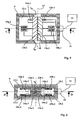
- FIGS. 5 to 7 show a second embodiment of a case 9 of MEMS technology according to the invention.
- each screen 13.1 or 13.2 is divided into two elements that are movable relative to each other.
- the substrate 12.1 carries two screen elements 13a.1 and 13b.1 and the substrate 12.2 carries two screen elements 13a.2 and 13b.2.
- Each screen element is displaceable by motor means 15a.1, 15b.1; 15a.2, 15b.2.
- Lock means 14a.1, 14b.1 or 14a.2, 14b.2 ensures at each pad the immobilization of each element of the screen considered.
- Each plate 12.1, 12.2 is connected to the electronic control means 11 which are designed to ensure the synchronized movement of the elements 13a.1, 13b.1, 13a.2, 13b.2 of the various plates.
- connector 16 which provides the interface between the wafers and the cable from the control means 11.
- the two elements constituting each screen are in contact with each other substantially at the axis 17 of the priming channel.
- the contact surfaces preferably have shape matching profiles 18a, 18b.
- the profiles consist of a succession of teeth defined by inclined planes with respect to the axis 17 of the channel 7.
- the juxtaposition of the teeth thus constitutes baffles which make it possible to improve the tightness to the gases generated by the initiator 6.
- the figure 7 shows the device in its armed position. Each motor means has moved an element in a direction Da or Db. The channel 7 is then released and the initiation of the load 5,5a is allowed.
- Each element 13a, 13b of each screen has thus moved by a distance substantially equal to one half-diameter of the channel.
- the movements are therefore of reduced amplitude which allows a faster arming.
- Figures 1 to 7 are schematic and do not prejudge the dimensions and proportions of the different components that are represented.
- each plate will be connected to the electronic control means that will ensure the synchronized movement of micro machined elements forming the screens carried by the various plates.
Landscapes
- Engineering & Computer Science (AREA)
- General Engineering & Computer Science (AREA)
- Air Bags (AREA)
- Micromachines (AREA)
- Aiming, Guidance, Guns With A Light Source, Armor, Camouflage, And Targets (AREA)
- Feeding, Discharge, Calcimining, Fusing, And Gas-Generation Devices (AREA)
- Motor Or Generator Frames (AREA)
- Vibration Prevention Devices (AREA)
- Burglar Alarm Systems (AREA)
- Toys (AREA)
Claims (8)
- Zünd-Sicherheitsvorrichtung für pyrotechnisches Gerät, wobei die Vorrichtung wenigstens eine Blende (13.1, 13.2) umfasst, die einen einen Initiator (6) und eine pyrotechnische Ladung (5, 5a) verbindenden Übertragungskanal (7, 7a, 7b) derartig verschließt, dass die Blende in der Form von wenigstens einem mikrobearbeiteten oder mikrogeätzten Element (13.1, 13.2) ausgeführt wird, das auf wenigstens einem Plättchen (12.1, 12.2) eines Substrats aufgebracht oder hergestellt ist, wobei die Vorrichtung dadurch gekennzeichnet ist, dass das Plättchen (12.1, 12.2) derartig orientiert ist, dass es sich im wesentlichen parallel zum Übertragungskanal (7, 7a, 7b) befindet, der so vor der Blende (13.1, 13.2) im Bereich dessen Dicke mündet, wobei die pyrotechnische Ladung (5, 5a) und der Initiator (6) sich so an beiden Seiten der Blende (13.1, 13.2) und vor der Dicke der Blende befinden.
- Sicherheitsvorrichtung nach Anspruch 1, dadurch gekennzeichnet, dass der Übertragungskanal (7, 7a, 7b) einen Querschnitt aufweist, dessen Fläche kleiner oder gleich 1 mm2 ist, wobei sie noch größer als die Zündfläche der pyrotechnischen Ladung (5, 5a) gewählt ist.
- Sicherheitsvorrichtung nach einem der Ansprüche 1 oder 2, dadurch gekennzeichnet, dass die Blende (13.1, 13.2) durch die Einwirkung von Motormitteln (15.1, 15.2) zwischen einer Sicherheitsposition, in der sie den Übertragungskanal (7, 7a, 7b) verschließt, und einer scharfen Position, in der sie wenigstens teilweise einen Teil des Übertragungskanals freigibt, beweglich ist, wobei die Motormittel in der Form von mikrobearbeiteten oder mikrogeätzten Teilen auf dem oder den Plättchen ausgeführt sind.
- Sicherheitsvorrichtung nach einem der Ansprüche 1 bis 3, dadurch gekennzeichnet, dass sie wenigstens zwei aufeinander gestapelte mikrobearbeitete oder mikrogeätzte Plättchen (12.1, 12.2) umfasst, wobei Steuermittel (11) eine synchronisierte Verlagerung der Blenden oder Blendenelemente der verschiedenen Plättchen gewährleisten.
- Sicherheitsvorrichtung nach einem der Ansprüche 1 bis 3, dadurch gekennzeichnet, dass die Blende (13.1, 13.2) wenigstens zwei Elemente (13a.1, 13b.1; 13a.2, 13b.2) umfasst, die sich zueinander verlagern können, um den Übertragungskanal (7, 7a, 7b) freizusetzen.
- Sicherheitsvorrichtung nach Anspruch 5, dadurch gekennzeichnet, dass die Elemente (13a.1, 13b.1 ; 13a.2, 13b.2) der Blenden im Bereich ihrer Kontaktzone Profile (18a.1, 18b.1) mit übereinstimmender Gestalt umfassen, deren Aneinanderfügung wenigstens ein Hindernis darstellt, das eine Dichtigkeit gegenüber den durch den Initiator erzeugten Gasen gewährleistet.
- Sicherheitsvorrichtung nach einem der Ansprüche 3 bis 6, dadurch gekennzeichnet, dass die Motormittel (15.1, 15.2; 15a.1, 15a.2; 15b.1, 15b.2) derartig ausgelegt sind, dass eine Reversibilität der Verlagerungen der Blende oder der Blenden gewährleistet wird.
- Sicherheitsvorrichtung nach einem der Ansprüche 1 bis 7, dadurch gekennzeichnet, dass jede Blende oder jedes Blendenelement durch einen mikrobearbeiteten oder mikrogeätzten Riegel (14.1, 14.2; 14a.1, 14a.2; 14b.1, 14b.2) auf dem betreffenden Plättchen (12.1, 12.2) in Sicherheitsposition gehalten wird.
Applications Claiming Priority (1)
| Application Number | Priority Date | Filing Date | Title |
|---|---|---|---|
| FR0511121A FR2892810B1 (fr) | 2005-10-27 | 2005-10-27 | Dispositif de securite pyrotechnique a ecran micro usine |
Publications (2)
| Publication Number | Publication Date |
|---|---|
| EP1780496A1 EP1780496A1 (de) | 2007-05-02 |
| EP1780496B1 true EP1780496B1 (de) | 2009-07-29 |
Family
ID=36609317
Family Applications (1)
| Application Number | Title | Priority Date | Filing Date |
|---|---|---|---|
| EP06291655A Active EP1780496B1 (de) | 2005-10-27 | 2006-10-25 | Pyrotechnische Sicherheitsvorrichtung mit mikrobearbeitetem Schild. |
Country Status (6)
| Country | Link |
|---|---|
| US (1) | US7444937B2 (de) |
| EP (1) | EP1780496B1 (de) |
| AT (1) | ATE438075T1 (de) |
| DE (1) | DE602006008086D1 (de) |
| FR (1) | FR2892810B1 (de) |
| NO (1) | NO338051B1 (de) |
Families Citing this family (18)
| Publication number | Priority date | Publication date | Assignee | Title |
|---|---|---|---|---|
| FR2892810B1 (fr) * | 2005-10-27 | 2010-05-14 | Giat Ind Sa | Dispositif de securite pyrotechnique a ecran micro usine |
| FR2892809B1 (fr) * | 2005-10-27 | 2010-07-30 | Giat Ind Sa | Dispositif de securite pyrotechnique a dimensions reduites |
| FR2926134B1 (fr) | 2008-01-07 | 2010-03-26 | Nexter Munitions | Dispositif de securite et d'armement micro-usine ou micro-grave |
| US9285198B2 (en) * | 2008-02-12 | 2016-03-15 | Pacific Scientific Energetic Materials Company | Arm-fire devices and methods for pyrotechnic systems |
| FR2932561B1 (fr) * | 2008-06-11 | 2010-08-20 | Nexter Munitions | Micro initiateur securise |
| FR2944348A1 (fr) | 2009-04-10 | 2010-10-15 | Nexter Munitions | Dispositif de mise a feu de munition par percussion |
| FR2962210A1 (fr) | 2010-07-02 | 2012-01-06 | Nexter Munitions | Dispositif de securite et d'armement a verrou inertiel de technologie mems |
| FR2962209B1 (fr) | 2010-07-02 | 2012-07-13 | Nexter Munitions | Reliefs anti adherence pour dispositif de securite et d'armement |
| FR2965044B1 (fr) * | 2010-09-22 | 2012-08-24 | Nexter Munitions | Dispositif de securite et d'armement pour projectile explosif gyrostabilise et dispositif d'amorcage mettant en oeuvre un tel dispositif de securite et d'armement |
| FR2971050B1 (fr) | 2011-01-31 | 2013-01-18 | Nexter Munitions | Dispositif de securite et d'armement pour une chaine pyrotechnique d'un projectile |
| FR2971049B1 (fr) | 2011-01-31 | 2013-01-18 | Nexter Munitions | Dispositif de temporisation d'un mouvement d'une masselotte micro-usinee et dispositif de securite et d'armement comprenant un tel dispositif de temporisation |
| FR2971048B1 (fr) | 2011-01-31 | 2013-01-11 | Nexter Munitions | Dispositif de securite et d'armement a verrou cassable |
| IL213830A (en) * | 2011-06-29 | 2017-07-31 | Rafael Advanced Defense Systems Ltd | Controlled pyrotechnic chain |
| FR2981443B1 (fr) * | 2011-10-17 | 2013-11-29 | Sme | Generateur de gaz muni d'un organe de securite pour les cas d'echauffements lents |
| US8971048B2 (en) | 2013-03-06 | 2015-03-03 | Alliant Techsystems Inc. | Self-locating electronics package precursor structure, method for configuring an electronics package, and electronics package |
| CN109141145B (zh) * | 2017-06-27 | 2021-06-29 | 南京理工大学 | 基于低温共烧陶瓷的灵巧起爆器 |
| CN109029138B (zh) * | 2018-09-13 | 2020-02-11 | 北京理工大学 | 一种应用于小口径弹的mems安全系统一体化装置及其方法 |
| FR3110687B1 (fr) | 2020-05-20 | 2022-05-27 | Nexter Munitions | Projectile sous calibré et procédé de neutralisation d'un objectif en mettant en oeuvre un tel projectile. |
Family Cites Families (24)
| Publication number | Priority date | Publication date | Assignee | Title |
|---|---|---|---|---|
| US617650A (en) * | 1899-01-10 | Car-brake | ||
| US3750589A (en) * | 1971-12-13 | 1973-08-07 | Honeywell Inc | Centrifugally driven spin device |
| FR2650662B1 (fr) | 1989-08-01 | 1991-10-11 | France Etat Armement | Dispositif d'amorcage de chaine pyrotechnique pour sous-munition d'obus cargo |
| US6173650B1 (en) | 1999-06-30 | 2001-01-16 | The United States Of America As Represented By The Secretary Of The Navy | MEMS emergetic actuator with integrated safety and arming system for a slapper/EFI detonator |
| FR2801099B1 (fr) | 1999-11-17 | 2002-10-11 | Giat Ind Sa | Systeme d'amorcage de la charge explosive d'une sous- munition |
| US6374739B1 (en) * | 2000-06-16 | 2002-04-23 | The United States Of America As Represented By The Secretary Of The Navy | Lockable electro-optical high voltage apparatus and method for slapper detonators |
| US6431071B1 (en) * | 2000-09-18 | 2002-08-13 | Trw Inc. | Mems arm fire and safe and arm devices |
| US6705231B1 (en) * | 2000-12-04 | 2004-03-16 | The United States Of America As Represented By The Secretary Of The Army | Safing and arming device for artillery submunitions |
| US6622629B2 (en) * | 2001-10-17 | 2003-09-23 | Northrop Grumman Corporation | Submunition fuzing and self-destruct using MEMS arm fire and safe and arm devices |
| US6564716B1 (en) * | 2001-12-05 | 2003-05-20 | Kdi Precision Products, Inc. | Fuzes having centrifugal arming lock for a munition |
| US20040027029A1 (en) | 2002-08-07 | 2004-02-12 | Innovative Techology Licensing, Llc | Lorentz force microelectromechanical system (MEMS) and a method for operating such a MEMS |
| US6691513B1 (en) | 2002-08-16 | 2004-02-17 | Pc Lens Corporation | System and method for providing an improved electrothermal actuator for a micro-electro-mechanical device |
| KR100468853B1 (ko) | 2002-08-30 | 2005-01-29 | 삼성전자주식회사 | 절연 물질에 구현된 mems 콤브 액추에이터와 그제조방법 |
| US6965189B2 (en) | 2002-09-20 | 2005-11-15 | Monodrive Inc. | Bending actuators and sensors constructed from shaped active materials and methods for making the same |
| US6634301B1 (en) * | 2002-09-26 | 2003-10-21 | The United States Of America As Represented By The Secretary Of The Navy | Enclosed ignition flare igniter |
| US6964231B1 (en) * | 2002-11-25 | 2005-11-15 | The United States Of America As Represented By The Secretary Of The Army | Miniature MEMS-based electro-mechanical safety and arming device |
| GB0305414D0 (en) * | 2003-03-08 | 2003-04-16 | Qinetiq Ltd | Electronic safety and arming unit |
| US7069861B1 (en) * | 2003-04-08 | 2006-07-04 | The United States Of America As Represented By The Secretary Of The Army | Micro-scale firetrain for ultra-miniature electro-mechanical safety and arming device |
| US7055437B1 (en) * | 2003-04-08 | 2006-06-06 | The United States Of America As Represented By The Secretary Of The Army | Micro-scale firetrain for ultra-miniature electro-mechanical safety and arming device |
| US7051656B1 (en) * | 2003-08-14 | 2006-05-30 | Sandia Corporation | Microelectromechanical safing and arming apparatus |
| US7597046B1 (en) * | 2003-12-03 | 2009-10-06 | The United States Of America As Represented By The Secretary Of The Navy | Integrated thin film explosive micro-detonator |
| US7216589B2 (en) | 2004-01-27 | 2007-05-15 | Lucent Technologies Inc. | Fuse for projected ordnance |
| FR2892809B1 (fr) * | 2005-10-27 | 2010-07-30 | Giat Ind Sa | Dispositif de securite pyrotechnique a dimensions reduites |
| FR2892810B1 (fr) * | 2005-10-27 | 2010-05-14 | Giat Ind Sa | Dispositif de securite pyrotechnique a ecran micro usine |
-
2005
- 2005-10-27 FR FR0511121A patent/FR2892810B1/fr not_active Expired - Fee Related
-
2006
- 2006-10-23 US US11/584,631 patent/US7444937B2/en active Active
- 2006-10-25 AT AT06291655T patent/ATE438075T1/de not_active IP Right Cessation
- 2006-10-25 DE DE602006008086T patent/DE602006008086D1/de active Active
- 2006-10-25 EP EP06291655A patent/EP1780496B1/de active Active
- 2006-10-26 NO NO20064898A patent/NO338051B1/no unknown
Also Published As
| Publication number | Publication date |
|---|---|
| NO20064898L (no) | 2007-04-30 |
| DE602006008086D1 (de) | 2009-09-10 |
| NO338051B1 (no) | 2016-07-25 |
| ATE438075T1 (de) | 2009-08-15 |
| FR2892810A1 (fr) | 2007-05-04 |
| FR2892810B1 (fr) | 2010-05-14 |
| US20070101888A1 (en) | 2007-05-10 |
| US7444937B2 (en) | 2008-11-04 |
| EP1780496A1 (de) | 2007-05-02 |
Similar Documents
| Publication | Publication Date | Title |
|---|---|---|
| EP1780496B1 (de) | Pyrotechnische Sicherheitsvorrichtung mit mikrobearbeitetem Schild. | |
| EP1780495B1 (de) | Kompakte pyrotechnische Sicherheitsvorrichtung. | |
| EP0048204B1 (de) | Patrone mit pyrotechnisch betätigter Nutzladung und mit Sicherheitseinrichtungen | |
| FR2669725A1 (fr) | Detonateur pyrotechnique a connexions coaxiales. | |
| EP2077431A2 (de) | Feinmechanisch bearbeitete oder mikro-gravierte Sicherheits- und Bewaffnungsvorrichtung | |
| EP0687888B1 (de) | Abfeuervorrichtung für eine pyrotechnische Ladung mit einem Zünderkopf, insbesondere für Handgranateur, mit drei Funktionsweisen | |
| EP2482027B1 (de) | Sicherheits- und Zündvorrichtung für eine pyrotechnische Kette eines Geschosses | |
| EP2304385B1 (de) | Sicherer mikroinitiator | |
| EP0942257B1 (de) | Mine, insbesondere zur Panzer- oder Fahrzeugbekämpfung, mit Mitteln zur Bestätigung des Vorhandenseins eines Ziels | |
| EP2482028B1 (de) | Sicherheits- und Zündvorrichtung mit einem zerbrechlichen Riegel | |
| FR2661725A1 (fr) | Dispositif pour separer deux espaces en cas d'elevation de temperature, procede pour realiser ce dispositif et munition comportant un tel dispositif. | |
| EP2462403B1 (de) | Sicherheitsfüllvorrichtung für munition | |
| FR2934042A1 (fr) | Dispositif de mise a feu pour engins pyrotechniques. | |
| EP1530020B1 (de) | Zündvorrichtung für mindestens zwei pyrotechnische Zusammensetzungen oder antreibende Ladungen eines Projektiles | |
| FR2678724A1 (fr) | Dispositif de securite et de mise a feu pre-programmee pour charge militaire. | |
| EP0233431B1 (de) | Patrone mit einem eine pyrotechnische Ladung tragenden Geschosskörper | |
| EP0559520B1 (de) | Barometrisches Sicherheitsventil und einer eine ähnliche pyrotechnische Vorrichtung enthaltender Gegenstand | |
| EP0320401B1 (de) | Vorrichtung zum Ausrichten mehrerer Elemente entlang einer Linie, insbesondere für eine Zündkette | |
| EP0230196A1 (de) | Geschoss mit pyrotechnischer Ladung | |
| EP0709646A1 (de) | Aufschlagzünder mit doppelter Sicherheit | |
| FR2817955A1 (fr) | Dispositif d'amorcage pour charge explosive et charge formee incorporant un tel dispositif d'amorcage | |
| FR2829662A1 (fr) | Suspension pour module electronique devant fonctionner durant et apres impacts severes | |
| FR2634013A1 (fr) | Dispositif de securite et d'armement pour un sous-projectile dispose a l'interieur d'un conteneur et libere par ce dernier sur trajectoire | |
| FR2526156A1 (fr) | Securite pour allumeur electrique | |
| FR2724451A1 (fr) | Equipement de securite de chaine pyrotechnique |
Legal Events
| Date | Code | Title | Description |
|---|---|---|---|
| PUAI | Public reference made under article 153(3) epc to a published international application that has entered the european phase |
Free format text: ORIGINAL CODE: 0009012 |
|
| AK | Designated contracting states |
Kind code of ref document: A1 Designated state(s): AT BE BG CH CY CZ DE DK EE ES FI FR GB GR HU IE IS IT LI LT LU LV MC NL PL PT RO SE SI SK TR |
|
| AX | Request for extension of the european patent |
Extension state: AL BA HR MK YU |
|
| 17P | Request for examination filed |
Effective date: 20071025 |
|
| 17Q | First examination report despatched |
Effective date: 20071213 |
|
| AKX | Designation fees paid |
Designated state(s): AT BE BG CH CY CZ DE DK EE ES FI FR GB GR HU IE IS IT LI LT LU LV MC NL PL PT RO SE SI SK TR |
|
| GRAP | Despatch of communication of intention to grant a patent |
Free format text: ORIGINAL CODE: EPIDOSNIGR1 |
|
| GRAS | Grant fee paid |
Free format text: ORIGINAL CODE: EPIDOSNIGR3 |
|
| GRAA | (expected) grant |
Free format text: ORIGINAL CODE: 0009210 |
|
| AK | Designated contracting states |
Kind code of ref document: B1 Designated state(s): AT BE BG CH CY CZ DE DK EE ES FI FR GB GR HU IE IS IT LI LT LU LV MC NL PL PT RO SE SI SK TR |
|
| REG | Reference to a national code |
Ref country code: GB Ref legal event code: FG4D Free format text: NOT ENGLISH |
|
| REG | Reference to a national code |
Ref country code: CH Ref legal event code: EP |
|
| REG | Reference to a national code |
Ref country code: CH Ref legal event code: NV Representative=s name: ING. MARCO ZARDI C/O M. ZARDI & CO. S.A. |
|
| REG | Reference to a national code |
Ref country code: IE Ref legal event code: FG4D |
|
| REF | Corresponds to: |
Ref document number: 602006008086 Country of ref document: DE Date of ref document: 20090910 Kind code of ref document: P |
|
| REG | Reference to a national code |
Ref country code: SE Ref legal event code: TRGR |
|
| PG25 | Lapsed in a contracting state [announced via postgrant information from national office to epo] |
Ref country code: LT Free format text: LAPSE BECAUSE OF FAILURE TO SUBMIT A TRANSLATION OF THE DESCRIPTION OR TO PAY THE FEE WITHIN THE PRESCRIBED TIME-LIMIT Effective date: 20090729 Ref country code: AT Free format text: LAPSE BECAUSE OF FAILURE TO SUBMIT A TRANSLATION OF THE DESCRIPTION OR TO PAY THE FEE WITHIN THE PRESCRIBED TIME-LIMIT Effective date: 20090729 Ref country code: FI Free format text: LAPSE BECAUSE OF FAILURE TO SUBMIT A TRANSLATION OF THE DESCRIPTION OR TO PAY THE FEE WITHIN THE PRESCRIBED TIME-LIMIT Effective date: 20090729 Ref country code: IS Free format text: LAPSE BECAUSE OF FAILURE TO SUBMIT A TRANSLATION OF THE DESCRIPTION OR TO PAY THE FEE WITHIN THE PRESCRIBED TIME-LIMIT Effective date: 20091129 Ref country code: ES Free format text: LAPSE BECAUSE OF FAILURE TO SUBMIT A TRANSLATION OF THE DESCRIPTION OR TO PAY THE FEE WITHIN THE PRESCRIBED TIME-LIMIT Effective date: 20091109 |
|
| PG25 | Lapsed in a contracting state [announced via postgrant information from national office to epo] |
Ref country code: SI Free format text: LAPSE BECAUSE OF FAILURE TO SUBMIT A TRANSLATION OF THE DESCRIPTION OR TO PAY THE FEE WITHIN THE PRESCRIBED TIME-LIMIT Effective date: 20090729 Ref country code: PL Free format text: LAPSE BECAUSE OF FAILURE TO SUBMIT A TRANSLATION OF THE DESCRIPTION OR TO PAY THE FEE WITHIN THE PRESCRIBED TIME-LIMIT Effective date: 20090729 Ref country code: LV Free format text: LAPSE BECAUSE OF FAILURE TO SUBMIT A TRANSLATION OF THE DESCRIPTION OR TO PAY THE FEE WITHIN THE PRESCRIBED TIME-LIMIT Effective date: 20090729 |
|
| REG | Reference to a national code |
Ref country code: IE Ref legal event code: FD4D |
|
| PG25 | Lapsed in a contracting state [announced via postgrant information from national office to epo] |
Ref country code: PT Free format text: LAPSE BECAUSE OF FAILURE TO SUBMIT A TRANSLATION OF THE DESCRIPTION OR TO PAY THE FEE WITHIN THE PRESCRIBED TIME-LIMIT Effective date: 20091129 Ref country code: BG Free format text: LAPSE BECAUSE OF FAILURE TO SUBMIT A TRANSLATION OF THE DESCRIPTION OR TO PAY THE FEE WITHIN THE PRESCRIBED TIME-LIMIT Effective date: 20091029 |
|
| BERE | Be: lapsed |
Owner name: NEXTER MUNITIONS Effective date: 20091031 |
|
| PG25 | Lapsed in a contracting state [announced via postgrant information from national office to epo] |
Ref country code: RO Free format text: LAPSE BECAUSE OF FAILURE TO SUBMIT A TRANSLATION OF THE DESCRIPTION OR TO PAY THE FEE WITHIN THE PRESCRIBED TIME-LIMIT Effective date: 20090729 Ref country code: CZ Free format text: LAPSE BECAUSE OF FAILURE TO SUBMIT A TRANSLATION OF THE DESCRIPTION OR TO PAY THE FEE WITHIN THE PRESCRIBED TIME-LIMIT Effective date: 20090729 Ref country code: IE Free format text: LAPSE BECAUSE OF FAILURE TO SUBMIT A TRANSLATION OF THE DESCRIPTION OR TO PAY THE FEE WITHIN THE PRESCRIBED TIME-LIMIT Effective date: 20090729 Ref country code: EE Free format text: LAPSE BECAUSE OF FAILURE TO SUBMIT A TRANSLATION OF THE DESCRIPTION OR TO PAY THE FEE WITHIN THE PRESCRIBED TIME-LIMIT Effective date: 20090729 Ref country code: DK Free format text: LAPSE BECAUSE OF FAILURE TO SUBMIT A TRANSLATION OF THE DESCRIPTION OR TO PAY THE FEE WITHIN THE PRESCRIBED TIME-LIMIT Effective date: 20090729 |
|
| PG25 | Lapsed in a contracting state [announced via postgrant information from national office to epo] |
Ref country code: MC Free format text: LAPSE BECAUSE OF NON-PAYMENT OF DUE FEES Effective date: 20091031 Ref country code: SK Free format text: LAPSE BECAUSE OF FAILURE TO SUBMIT A TRANSLATION OF THE DESCRIPTION OR TO PAY THE FEE WITHIN THE PRESCRIBED TIME-LIMIT Effective date: 20090729 |
|
| PLBE | No opposition filed within time limit |
Free format text: ORIGINAL CODE: 0009261 |
|
| STAA | Information on the status of an ep patent application or granted ep patent |
Free format text: STATUS: NO OPPOSITION FILED WITHIN TIME LIMIT |
|
| 26N | No opposition filed |
Effective date: 20100503 |
|
| PG25 | Lapsed in a contracting state [announced via postgrant information from national office to epo] |
Ref country code: BE Free format text: LAPSE BECAUSE OF NON-PAYMENT OF DUE FEES Effective date: 20091031 Ref country code: GR Free format text: LAPSE BECAUSE OF FAILURE TO SUBMIT A TRANSLATION OF THE DESCRIPTION OR TO PAY THE FEE WITHIN THE PRESCRIBED TIME-LIMIT Effective date: 20091030 |
|
| PG25 | Lapsed in a contracting state [announced via postgrant information from national office to epo] |
Ref country code: LU Free format text: LAPSE BECAUSE OF NON-PAYMENT OF DUE FEES Effective date: 20091025 |
|
| PG25 | Lapsed in a contracting state [announced via postgrant information from national office to epo] |
Ref country code: HU Free format text: LAPSE BECAUSE OF FAILURE TO SUBMIT A TRANSLATION OF THE DESCRIPTION OR TO PAY THE FEE WITHIN THE PRESCRIBED TIME-LIMIT Effective date: 20100130 |
|
| PG25 | Lapsed in a contracting state [announced via postgrant information from national office to epo] |
Ref country code: TR Free format text: LAPSE BECAUSE OF FAILURE TO SUBMIT A TRANSLATION OF THE DESCRIPTION OR TO PAY THE FEE WITHIN THE PRESCRIBED TIME-LIMIT Effective date: 20090729 |
|
| PG25 | Lapsed in a contracting state [announced via postgrant information from national office to epo] |
Ref country code: CY Free format text: LAPSE BECAUSE OF FAILURE TO SUBMIT A TRANSLATION OF THE DESCRIPTION OR TO PAY THE FEE WITHIN THE PRESCRIBED TIME-LIMIT Effective date: 20090729 |
|
| REG | Reference to a national code |
Ref country code: FR Ref legal event code: PLFP Year of fee payment: 10 |
|
| REG | Reference to a national code |
Ref country code: FR Ref legal event code: PLFP Year of fee payment: 11 |
|
| REG | Reference to a national code |
Ref country code: FR Ref legal event code: PLFP Year of fee payment: 12 |
|
| REG | Reference to a national code |
Ref country code: FR Ref legal event code: PLFP Year of fee payment: 13 |
|
| REG | Reference to a national code |
Ref country code: NL Ref legal event code: HC Owner name: KNDS AMMO FRANCE; FR Free format text: DETAILS ASSIGNMENT: CHANGE OF OWNER(S), CHANGE OF OWNER(S) NAME; FORMER OWNER NAME: NEXTER MUNITIONS Effective date: 20250122 |
|
| PGFP | Annual fee paid to national office [announced via postgrant information from national office to epo] |
Ref country code: NL Payment date: 20250923 Year of fee payment: 20 Ref country code: IT Payment date: 20250923 Year of fee payment: 20 |
|
| PGFP | Annual fee paid to national office [announced via postgrant information from national office to epo] |
Ref country code: GB Payment date: 20250923 Year of fee payment: 20 |
|
| PGFP | Annual fee paid to national office [announced via postgrant information from national office to epo] |
Ref country code: FR Payment date: 20250924 Year of fee payment: 20 |
|
| PGFP | Annual fee paid to national office [announced via postgrant information from national office to epo] |
Ref country code: SE Payment date: 20250923 Year of fee payment: 20 |
|
| REG | Reference to a national code |
Ref country code: CH Ref legal event code: U11 Free format text: ST27 STATUS EVENT CODE: U-0-0-U10-U11 (AS PROVIDED BY THE NATIONAL OFFICE) Effective date: 20251101 |
|
| PGFP | Annual fee paid to national office [announced via postgrant information from national office to epo] |
Ref country code: DE Payment date: 20250923 Year of fee payment: 20 |
|
| PGFP | Annual fee paid to national office [announced via postgrant information from national office to epo] |
Ref country code: CH Payment date: 20251101 Year of fee payment: 20 |