EP1781390B1 - Procede de dessalinisation entraine par distillat msf et appareil - Google Patents
Procede de dessalinisation entraine par distillat msf et appareil Download PDFInfo
- Publication number
- EP1781390B1 EP1781390B1 EP05775302A EP05775302A EP1781390B1 EP 1781390 B1 EP1781390 B1 EP 1781390B1 EP 05775302 A EP05775302 A EP 05775302A EP 05775302 A EP05775302 A EP 05775302A EP 1781390 B1 EP1781390 B1 EP 1781390B1
- Authority
- EP
- European Patent Office
- Prior art keywords
- distillate
- msf
- stage
- med
- heat
- Prior art date
- Legal status (The legal status is an assumption and is not a legal conclusion. Google has not performed a legal analysis and makes no representation as to the accuracy of the status listed.)
- Expired - Lifetime
Links
Images



Classifications
-
- B—PERFORMING OPERATIONS; TRANSPORTING
- B01—PHYSICAL OR CHEMICAL PROCESSES OR APPARATUS IN GENERAL
- B01D—SEPARATION
- B01D3/00—Distillation or related exchange processes in which liquids are contacted with gaseous media, e.g. stripping
- B01D3/06—Flash distillation
-
- B—PERFORMING OPERATIONS; TRANSPORTING
- B01—PHYSICAL OR CHEMICAL PROCESSES OR APPARATUS IN GENERAL
- B01D—SEPARATION
- B01D3/00—Distillation or related exchange processes in which liquids are contacted with gaseous media, e.g. stripping
- B01D3/06—Flash distillation
- B01D3/065—Multiple-effect flash distillation (more than two traps)
-
- B—PERFORMING OPERATIONS; TRANSPORTING
- B01—PHYSICAL OR CHEMICAL PROCESSES OR APPARATUS IN GENERAL
- B01D—SEPARATION
- B01D3/00—Distillation or related exchange processes in which liquids are contacted with gaseous media, e.g. stripping
- B01D3/10—Vacuum distillation
-
- C—CHEMISTRY; METALLURGY
- C02—TREATMENT OF WATER, WASTE WATER, SEWAGE, OR SLUDGE
- C02F—TREATMENT OF WATER, WASTE WATER, SEWAGE, OR SLUDGE
- C02F1/00—Treatment of water, waste water, or sewage
- C02F1/02—Treatment of water, waste water, or sewage by heating
- C02F1/04—Treatment of water, waste water, or sewage by heating by distillation or evaporation
- C02F1/06—Flash evaporation
-
- B—PERFORMING OPERATIONS; TRANSPORTING
- B01—PHYSICAL OR CHEMICAL PROCESSES OR APPARATUS IN GENERAL
- B01D—SEPARATION
- B01D19/00—Degasification of liquids
- B01D19/0068—General arrangements, e.g. flowsheets
-
- C—CHEMISTRY; METALLURGY
- C02—TREATMENT OF WATER, WASTE WATER, SEWAGE, OR SLUDGE
- C02F—TREATMENT OF WATER, WASTE WATER, SEWAGE, OR SLUDGE
- C02F1/00—Treatment of water, waste water, or sewage
- C02F1/44—Treatment of water, waste water, or sewage by dialysis, osmosis or reverse osmosis
- C02F1/441—Treatment of water, waste water, or sewage by dialysis, osmosis or reverse osmosis by reverse osmosis
-
- C—CHEMISTRY; METALLURGY
- C02—TREATMENT OF WATER, WASTE WATER, SEWAGE, OR SLUDGE
- C02F—TREATMENT OF WATER, WASTE WATER, SEWAGE, OR SLUDGE
- C02F2103/00—Nature of the water, waste water, sewage or sludge to be treated
- C02F2103/08—Seawater, e.g. for desalination
-
- Y—GENERAL TAGGING OF NEW TECHNOLOGICAL DEVELOPMENTS; GENERAL TAGGING OF CROSS-SECTIONAL TECHNOLOGIES SPANNING OVER SEVERAL SECTIONS OF THE IPC; TECHNICAL SUBJECTS COVERED BY FORMER USPC CROSS-REFERENCE ART COLLECTIONS [XRACs] AND DIGESTS
- Y02—TECHNOLOGIES OR APPLICATIONS FOR MITIGATION OR ADAPTATION AGAINST CLIMATE CHANGE
- Y02A—TECHNOLOGIES FOR ADAPTATION TO CLIMATE CHANGE
- Y02A20/00—Water conservation; Efficient water supply; Efficient water use
- Y02A20/124—Water desalination
-
- Y—GENERAL TAGGING OF NEW TECHNOLOGICAL DEVELOPMENTS; GENERAL TAGGING OF CROSS-SECTIONAL TECHNOLOGIES SPANNING OVER SEVERAL SECTIONS OF THE IPC; TECHNICAL SUBJECTS COVERED BY FORMER USPC CROSS-REFERENCE ART COLLECTIONS [XRACs] AND DIGESTS
- Y02—TECHNOLOGIES OR APPLICATIONS FOR MITIGATION OR ADAPTATION AGAINST CLIMATE CHANGE
- Y02A—TECHNOLOGIES FOR ADAPTATION TO CLIMATE CHANGE
- Y02A20/00—Water conservation; Efficient water supply; Efficient water use
- Y02A20/124—Water desalination
- Y02A20/131—Reverse-osmosis
Definitions
- the invention relates to improvements in processes involving multiple stage flash distillation (MSF) generally and in particular the MSF distillation of seawater i.e. desalination to produce potable water, and relates advantageously to processes including MSF distillation of the kind in which a high top brine temperature is achievable (of the order of 120°C or more).
- MSF multiple stage flash distillation
- the known conventional processes for the desalination of salt water to produce potable water include, for example, multistage flash distillation (MSF), multiple effect distillation (MED), reverse osmosis (RO) and vapour compression (VC) distillation.
- MSF multistage flash distillation
- MED multiple effect distillation
- RO reverse osmosis
- VC vapour compression
- the seawater distillate flow condensed in an MSF tube bundle is forced partly to re-flash when it is transferred to a subsequent stage in an evaporator operating at a lower pressure.
- the vapour generated by the distillate flashing is mixed with the vapour generated by the brine flashing and thus uses part of the installed heat transfer surface that part being therefore unavailable for the condensation of the flashing brine.
- distillate trough collecting and transferring the distillate from the high to the low temperature stage of the MSF becomes increasingly cumbersome and takes space away from demisters and flashing brine release areas.
- the 'heat reject' section of a typical MSF plant uses external seawater cooling to maintain low temperature in the bottom temperature stages.
- this heat reject section the installed heat transfer surface is used both to produce new distillate by condensation of flashing brine and to condense the distillate flashed. Therefore the efficiency of this section of the plant is lower than the heat recovery and typically over 18% of the heat transfer area is used to condense re-flashed distillate.
- Multistage flash distillers are in common use worldwide for large scale desalination projects. Their performance depends on both the maximum brine temperature (top brine temperature or TBT) and the minimum brine temperature (bottom brine temperature or BBT) that can be used in the process. The higher the difference between the TBT and the BBT (the flashing range), the higher the plant productivity becomes.
- Modem conventional MSF plants operate at a top brine temperature ranging between 105 ° C and 112 ° C; and the brine and distillate temperature in the bottom stage of the heat recovery section varies between 65° and 50° and depends on the seawater cooling flow rate and temperature.
- An advanced MSF plant employing a combination of MSF and Nanofiltration technology allowing TBT to exceed 120° C (as disclosed in Awerbuch EP 1206414 ( WO 0114256 )) and this provides an even larger flashing range.
- the proposed invention relates to a modification to the MSF plant design which allows more brine from the MSF plant to flash in the heat rejection section of the evaporator and be condensed in the larger heat transfer surface made available for the condensation of brine.
- MED technology has been used for relatively small applications and operations at relatively lower temperatures.
- the design top temperature adopted for MED processes varies between 60°C and 70°C.
- the optimal membrane feed water ranges between 28 °C and 32 °C . At lower temperatures the membrane recovery ratio is low, therefore less permeate can be obtained from the membrane with higher energy consumption.
- the present invention makes available sensible heat from MSF distillate extracted stream at a sufficiently high temperature to both pre-heat seawater RO feed and/or MED feedwater.
- the present invention is directed to an improved process for desalinating salt water at optimal operating conditions by matching MED, RO or other processes, with MSF.
- the present invention provides a desalination process for the production of potable water comprising the steps of;
- the energy associated with the distillate extracted from the last stages of the MSF heat recovery section is recovered in another power or desalination cycle (e.g. MED or RO) operating at lower temperature.
- MED desalination cycle
- said at least one stage is a stage in which feedwater to the MSF separation process is preheated by the said at least one stream.
- said at least one stage is a stage of a second separation process.
- the second separation process is MED operating at lower temperature, which is, at least in part, thermally driven by heat extracted from said at least one distillate stream derived from MSF.
- Said at least one distillate stream may be flashed in a series of flash evaporation processes to provide heat by direct transfer from the brine to the MED process.
- said at least one distillate stream may be flashed to cool the distillate, and the fluid vapour is thermocompressed by ejectors to a high temperature and then input to a higher effect of the MED process.
- said at least one distillate stream may be subjected to a series of heat exchange steps in which heat is transferred from the distillate stream to the distillate of the MED.
- the second separation process may be a reverse osmosis (RO) process in which the distillate stream from the MSF is used to preheat the seawater feed to the RO process.
- RO reverse osmosis
- the heat extracted from the MSF in the form of distillate can be utilized as an energy source for a lower temperature process such as the MED.
- distillate can be either used in a liquid form to feed the MED or it can be flashed and recompressed and input to the MED first stage.
- the invention makes available energy from the MSF plant with a contemporary improvement of the MSF plant performances.
- the distillate extraction system from the MSF involves other advantages especially in the apparatus/plant, in fact because the distillate trough in the heat rejection section can be substantially smaller, and/or a larger space can be made available to a demister. This space is particularly precious in the heat reject section which is operating under high vacuum, handles large volumes of vapour and this therefore results in high vapour velocities in the demisters.
- the heat flashed in the last stages is not at all beneficial, necessary or required for the MSF distillation process, but could be used to preheat feed to membrane processes, as proposed.
- heat of reflashing distillate is condensing on heat transfer surfaces (HTS) and requires a tube area for condensation which could be used for condensing additional new vapour produced from flashing brine.
- the additional area not occupied by a distillate collector channel, can be used to increase the area of demisters, particularly in lower stages of MSF.
- the heat removed from MSF stages by taking distillate from MSF can be reflashed to lower temperature of MED effects, both to provide sensible heat to preheat feed in direct contact, or through feedwater heaters of MED.
- the result of removal of distillate from all or some strategically located stages of MSF plant will provide additional output of distilled water of existing and future MSF plants.
- the heat contained and the thermal potential of the distillate is recovered by hybridization with MED, VC or RO processes. This allows maximisation of production, both in MSF, as well as increasing efficiency of other desalination processes.
- the preferred process is to remove distillate every few stages and transfer the available heat by flashing in MED flash tanks which provide vapour to preheat the feed in direct contact with spray sub-cooled feed, or provide steam-vapour to feedwater heater.
- the improvement resides with the discovery that the extraction of the MSF distillate can be used to provide energy to another process cycle operating at a lower temperature. It has been discovered furthermore that the extraction brings about substantial improvements in the performance of MSF desalination plant from which the distillate is extracted These improvements are not suggested by the prior art.
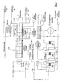
- a MSF shown generally as 100 which comprises heat reject stages 110 and heat recovery stages 120.
- the unflashed brine enters a second chamber, or stage, where it flashes to steam at a lower temperature, thereby producing an additional quantity of product water.
- the distillate from the first stage (101) passes to the distillate tray in the second stage and gives up some of its heat.
- the flash-cooling process is repeated from stage to stage until both the cooled brine and the cooled distillate are finally discharged from the plant as blowdown brine and product water, respectively.
- the recirculating brine (121) stream flowing through the interior of the tubes that condenses the vapour in each stage serves to remove the latent heat of condensation.
- the recirculating brine is pre-heated, simultaneously recovering the energy of the condensing vapour.
- This portion of the multistage flash distillation plant is called the "heat recovery” section.
- the pre-heated brine is finally brought up to the maximum operating temperature in a brine heater (122) supplied with steam from an external source (S).
- S external source
- the cool end of the plant, called the "heat rejection” section has the task to both remove the waste heat by external cooling seawater and produce distillate by condensing part of the remaining part-flashing brine from the heat recovery section.
- a fraction (111) of this cooling stream, branched downstream of the heat reject section, is pre-heated and becomes make-up water.
- MSF production increases without any substantial decrease in the performance ratio and therefore without any increased external steam requirement.
- the energy of the distillate stream is used as an energy source for a distinct MED separator shown generally as 200 comprising a series of effects 201, 202, 203,
- distillate as a heat source for an MED process allows the MED to operate with very low supplied (external) heat consumption and increases the energy efficiency of the system.
- the invention grants some environmental benefits. As indicated in table 1 below, with the same seawater flow rate through the heat reject section both the bottom brine temperature (BBT) and the heat reject outlet temperature is lower. Alternatively the cooling water flow rate through the heat reject section can be reduced, or a combination of the two may be achieved. Both aspects bring about an improvement of the environmental impact.
- Table 1 summarizes the advantages achieved by the present invention in the both the options of retrofitting the concept in an existing site or introducing it as a design feature for a new plant.
- Table 1 summary of invention benefits EXISTING PLANT (retrofit) NEW PLANT Increase in MSF Distillate output without decrease in performance ratio. Increase in MSF Distillate output and increase in plant performance ratio. Extraction of a thermal stream usable in another process Extraction of a thermal stream usable in another process . Modification of the internal distiller layout with possibility to increase demister/release areas and decrease distillate tray. Optimization in internal distiller layout with possibility to increase demister/release areas and decrease distillate tray. Decrease in demisters velocity and increase in distillate purity. Protections of purity of the main distillate stream by removal before reject section.
- the invention is retrofitted in an existing MSF plant there are unavoidable constraints given by the existing design which may prevent the increase of the demisters area. In this case as indicated in table 1 the plant output will increase. The plant percentage increase is indicated in Figure 5 and Table 2. If the invention is applied to a new MSF plant the same may imply a redesign of the evaporator internal arrangement in the last stage of the heat reject section which makes available more space to demisters and therefore allows an increase in the performance ratio.
- Table 2 shows a comparative analysis of a 5 MIGD (million Imperial gallon per day) 17 stages MSF plant operating under the same conditions of top brine temperature, seawater temperature and brine recirculation flow rate with the extraction of the distillate flow (in accordance with the invention) from the 14 th stage.
- the desalination apparatus conceived includes distillate removal from MSF to be flashed in a tank to cool the distillate and the vapour flashed are thermo- compressed through ejectors to higher temperature entering higher stage of MSF
- One of the benefits of the invented apparatus includes distillate removal from MSF to be flashed in a flashing tank to cool the distillate, and distillates and the flashed vapour are condensed in a process operating at lower temperature to obtained a double distilled product of extremely high purity below .01 ppm TDS.
- Figure 1 illustrates a basic flow diagram of an MSF - MED integrated system with an MED first effect heated up by distillate extracted from the MSF instead of condensing steam.
- the MED plant is in all aspects similar to a conventional MED plant with the difference that the first effect is fed by distillate from the MSF instead of steam.
- the distillate is cooled in the first effect by transfer of heat to fresh seawater in the MED effect.
- the desalination apparatus conceived includes the heat transfer in a series of flashing tanks providing flashed vapour by direct contact from the distillate to the MED.
- the desalination apparatus according to the invention provides for the distillate removed from MSF to a flashing tank to cool the distillate and the flashed vapour are thermo- compressed by ejectors to a higher temperature before entering a higher effect of MED
- An alternative desalination apparatus provides for the heat transfer to be conducted in a series of heat exchangers between the MSF distillate and the distillate of MED
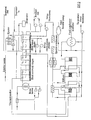
- FIG. 4 illustrates a hybrid MSF/RO plant with RO feed water heated up by MSF distillate extracted as previously indicated.
- the membrane feed water is heated up to 28- 30 degrees by the sensible heat of the distillate with the benefit of maintaining a higher permeate recovery ratio a lower specific power consumption and a more constant working temperature to the membrane inlet which is reflected in a longer membrane life.
- the desalination apparatus provides for the apparatus for the heat transfer is a series of flashing tanks providing flashed vapour by direct contact from the distillate to the RO feed.
- Alternative embodiment of this invention provides for distillate removal from MSF to be flashed in a flashing tank to cool the distillate and the vapour flashed are thermo- compressed by ejectors to higher temperature to heat the RO feed.
- Another alternative provides for desalination apparatus for the heat transfer to be heat exchangers between the MSF distillate and the RO feed.
- the graph shown in Figure 5 is based on a nominal 5 million imperial gallons per day (MIGD) throughput. With throughputs at present exceeding 15 MIGD the increase in output would be proportionally increased.
- MIGD imperial gallons per day
Landscapes
- Chemical & Material Sciences (AREA)
- Chemical Kinetics & Catalysis (AREA)
- Organic Chemistry (AREA)
- Environmental & Geological Engineering (AREA)
- Water Supply & Treatment (AREA)
- Engineering & Computer Science (AREA)
- Life Sciences & Earth Sciences (AREA)
- Hydrology & Water Resources (AREA)
- Heat Treatment Of Water, Waste Water Or Sewage (AREA)
- Vaporization, Distillation, Condensation, Sublimation, And Cold Traps (AREA)
- Saccharide Compounds (AREA)
- Separation Using Semi-Permeable Membranes (AREA)
- Glass Compositions (AREA)
- Transition And Organic Metals Composition Catalysts For Addition Polymerization (AREA)
Claims (11)
- Procédé de dessalage pour la production d'eau potable comprenant les étapes:a) d'extraction d'au moins un courant de distillat (150) provenant d'au moins une phase à température supérieure (109) d'un procédé de séparation MSF (distillation à détentes étagées) (100); etb) d'approvisionnement dudit au moins un courant de distillat vers au moins une phase (201) d'un procédé de séparation (200) fonctionnant à une température inférieure à ladite température supérieure de manière à maximiser l'utilisation de chaleur sensible dans ledit courant de distillat par un transfert de chaleur dans ladite au moins une phase, pour abaisser l'apport de chaleur externe de ladite au moins une phase et du procédé globalement.
- Procédé de dessalage suivant la revendication 1, dans lequel ladite au moins une phase est une phase dans laquelle l'eau d'alimentation du procédé de séparation MSF est préchauffée par ledit au moins un courant.
- Procédé de dessalage suivant la revendication 1 ou la revendication 2, dans lequel ladite au moins une phase (201) est une phase d'un deuxième procédé de séparation (200).
- Procédé de dessalage suivant la revendication 3, dans lequel le deuxième procédé de séparation est un procédé MED (distillation à multiples effets) (200) fonctionnant à une température inférieure, qui est, au moins en partie, thermiquement conduit par la chaleur extraite dudit au moins un courant de distillat dérivé du procédé MSF.
- Procédé de dessalage suivant la revendication 4, dans lequel ledit au moins un courant de distillat est évaporé rapidement dans une série de procédés d'évaporation éclair (Fig. 2) pour donner de la chaleur par un transfert direct de la saumure au procédé MED.
- Procédé de dessalage suivant la revendication 4 ou la revendication 5, dans lequel ledit au moins un courant de distillat est évaporé rapidement pour refroidir le distillat et la vapeur de fluide est comprimée thermiquement par des éjecteurs (Fig. 2) à une température élevée et ensuite apportée en vue d'un effet supérieur du procédé MED.
- Procédé de dessalage suivant la revendication 4 ou la revendication 5, dans lequel ledit au moins un courant de distillat est soumis à une série d'étapes d'échange de chaleur dans lesquelles la chaleur est transférée du courant de distillat au distillat du procédé MED.
- Procédé de dessalage suivant la revendication 3, dans lequel le deuxième procédé de séparation est un procédé d'osmose inverse (RO) dans lequel le courant de distillat provenant du procédé MSF est utilisé pour préchauffer l'alimentation d'eau de mer vers le procédé RO.
- Procédé de dessalage suivant l'une quelconque des revendications précédentes, dans lequel la chaleur extraite du procédé MSF sous la forme d'un distillat est utilisée comme source d'énergie pour un procédé à température inférieure tel que le procédé MED.
- Procédé de dessalage suivant la revendication 9, dans lequel le distillat est utilisé sous une forme liquide pour alimenter le procédé MED.
- Procédé de dessalage suivant la revendication 9, dans lequel le distillat est évaporé rapidement et comprimé à nouveau et apporté à la première phase du procédé MED.
Priority Applications (2)
| Application Number | Priority Date | Filing Date | Title |
|---|---|---|---|
| PL05775302T PL1781390T3 (pl) | 2004-08-27 | 2005-08-26 | Sposób odsalania wykorzystujący destylat MSF oraz aparatura do tego procesu |
| CY20081100441T CY1107404T1 (el) | 2004-08-27 | 2008-04-21 | Οδηγουμενη απο αποσταγμα msf διαδικασια αφαλατωσης και μηχανισμος |
Applications Claiming Priority (2)
| Application Number | Priority Date | Filing Date | Title |
|---|---|---|---|
| GB0419117A GB2417435A (en) | 2004-08-27 | 2004-08-27 | MSF desalination system |
| PCT/GB2005/003329 WO2006021796A1 (fr) | 2004-08-27 | 2005-08-26 | Procede de dessalinisation entraine par distillat msf et appareil |
Publications (2)
| Publication Number | Publication Date |
|---|---|
| EP1781390A1 EP1781390A1 (fr) | 2007-05-09 |
| EP1781390B1 true EP1781390B1 (fr) | 2008-03-05 |
Family
ID=33104719
Family Applications (1)
| Application Number | Title | Priority Date | Filing Date |
|---|---|---|---|
| EP05775302A Expired - Lifetime EP1781390B1 (fr) | 2004-08-27 | 2005-08-26 | Procede de dessalinisation entraine par distillat msf et appareil |
Country Status (12)
| Country | Link |
|---|---|
| EP (1) | EP1781390B1 (fr) |
| JP (1) | JP2008510610A (fr) |
| KR (1) | KR20070050050A (fr) |
| CN (1) | CN100548424C (fr) |
| AT (1) | ATE387944T1 (fr) |
| CY (1) | CY1107404T1 (fr) |
| DE (1) | DE602005005204T2 (fr) |
| DK (1) | DK1781390T3 (fr) |
| ES (1) | ES2302224T3 (fr) |
| GB (1) | GB2417435A (fr) |
| PL (1) | PL1781390T3 (fr) |
| WO (1) | WO2006021796A1 (fr) |
Families Citing this family (15)
| Publication number | Priority date | Publication date | Assignee | Title |
|---|---|---|---|---|
| US7416666B2 (en) | 2002-10-08 | 2008-08-26 | Water Standard Company | Mobile desalination plants and systems, and methods for producing desalinated water |
| KR100781897B1 (ko) * | 2006-12-19 | 2007-12-03 | 두산중공업 주식회사 | 하이브리드 담수화 장치 및 방법 |
| KR100907662B1 (ko) | 2007-09-21 | 2009-07-14 | 두산중공업(주) | 히트파이프열방출기가 구비된 엠에스에프 해수 담수화 장치 |
| CN102502902B (zh) * | 2011-11-10 | 2013-07-03 | 集美大学 | 火电厂多级闪蒸海水淡化系统 |
| CN102849887B (zh) * | 2012-10-07 | 2013-08-07 | 中国海洋大学 | 一种海水淡化方法 |
| ES2473190B1 (es) * | 2014-01-20 | 2015-06-11 | Alex Hanganu Research, S.L. | Dispositivo de Destilación Multi-Efecto |
| WO2015107249A1 (fr) * | 2014-01-20 | 2015-07-23 | Alex Hanganu Research, S.L. | Dispositif de distillation à effets multiples med à efficatité he-med élevée |
| WO2015107250A1 (fr) * | 2014-01-20 | 2015-07-23 | Alex Hanganu Research, S.L. | Disposifif à conductance thermique élevée pour des systèmes à effets multiples de dessalement d'eau |
| AU2015245944B2 (en) * | 2014-04-11 | 2020-01-02 | Murdoch University | System and method for desalination |
| CN104089276A (zh) * | 2014-06-24 | 2014-10-08 | 首钢京唐钢铁联合有限责任公司 | 利用乏汽、循环冷却水的多级闪蒸处理系统 |
| WO2017172348A1 (fr) * | 2016-03-30 | 2017-10-05 | Veolia Water Technologies, Inc. | Système et procédé de préchauffage d'eau d'alimentation d'évaporateur |
| CN106587233B (zh) * | 2016-10-12 | 2019-02-19 | 王文领 | 一种煤化工气化黑水高温闪蒸气的综合利用方法 |
| WO2018132087A1 (fr) * | 2017-01-10 | 2018-07-19 | Kuwait Institute For Scientific Research | Système combiné de distillation à effets multiples et d'évaporation flash à étages multiples |
| PE20221897A1 (es) | 2020-03-10 | 2022-12-15 | Bechtel Energy Tech And Solutions Inc | Sistema de desalinizacion con eyector de baja energia |
| AU2022351167B2 (en) | 2021-09-24 | 2024-10-31 | Bechtel Energy Technologies & Solutions, Inc. | Low energy ejector desalination system |
Family Cites Families (8)
| Publication number | Priority date | Publication date | Assignee | Title |
|---|---|---|---|---|
| GB1165895A (en) * | 1965-07-15 | 1969-10-01 | Weir Westgarth Ltd | Improvements in or relating to the Desalination of Sea Water and other Saline Waters |
| US3489654A (en) * | 1967-01-09 | 1970-01-13 | American Hydrotherm Corp | Evaporation system and process |
| US3839160A (en) * | 1972-06-23 | 1974-10-01 | Hitachi Ltd | Multiple effect evaporator |
| JPS5450483A (en) * | 1977-09-30 | 1979-04-20 | Agency Of Ind Science & Technol | Multistage flash evaporator |
| JPS6186989A (ja) * | 1984-10-02 | 1986-05-02 | Ishikawajima Harima Heavy Ind Co Ltd | 複合海水淡水化設備 |
| DE3938012A1 (de) * | 1989-11-15 | 1991-05-16 | Serck Como Gmbh | Mehrstufige verdampferanlage fuer die wasserentsalzung |
| DE4431546A1 (de) * | 1994-09-05 | 1996-03-07 | Jakob Dr Ing Hois | Verfahren und Vorrichtung zum Entsalzen von Meerwasser |
| US6508936B1 (en) * | 1997-10-01 | 2003-01-21 | Saline Water Conversion Corporation | Process for desalination of saline water, especially water, having increased product yield and quality |
-
2004
- 2004-08-27 GB GB0419117A patent/GB2417435A/en not_active Withdrawn
-
2005
- 2005-08-26 WO PCT/GB2005/003329 patent/WO2006021796A1/fr not_active Ceased
- 2005-08-26 JP JP2007528981A patent/JP2008510610A/ja active Pending
- 2005-08-26 PL PL05775302T patent/PL1781390T3/pl unknown
- 2005-08-26 KR KR1020077004060A patent/KR20070050050A/ko not_active Ceased
- 2005-08-26 ES ES05775302T patent/ES2302224T3/es not_active Expired - Lifetime
- 2005-08-26 DE DE602005005204T patent/DE602005005204T2/de not_active Expired - Lifetime
- 2005-08-26 EP EP05775302A patent/EP1781390B1/fr not_active Expired - Lifetime
- 2005-08-26 AT AT05775302T patent/ATE387944T1/de active
- 2005-08-26 CN CNB2005800286949A patent/CN100548424C/zh not_active Expired - Fee Related
- 2005-08-26 DK DK05775302T patent/DK1781390T3/da active
-
2008
- 2008-04-21 CY CY20081100441T patent/CY1107404T1/el unknown
Also Published As
| Publication number | Publication date |
|---|---|
| GB0419117D0 (en) | 2004-09-29 |
| CN100548424C (zh) | 2009-10-14 |
| WO2006021796A1 (fr) | 2006-03-02 |
| KR20070050050A (ko) | 2007-05-14 |
| CY1107404T1 (el) | 2012-12-19 |
| ATE387944T1 (de) | 2008-03-15 |
| DK1781390T3 (da) | 2008-06-30 |
| DE602005005204T2 (de) | 2009-03-12 |
| CN101107051A (zh) | 2008-01-16 |
| GB2417435A (en) | 2006-03-01 |
| EP1781390A1 (fr) | 2007-05-09 |
| PL1781390T3 (pl) | 2008-08-29 |
| ES2302224T3 (es) | 2008-07-01 |
| DE602005005204D1 (de) | 2008-04-17 |
| JP2008510610A (ja) | 2008-04-10 |
Similar Documents
| Publication | Publication Date | Title |
|---|---|---|
| EP1781390B1 (fr) | Procede de dessalinisation entraine par distillat msf et appareil | |
| US8277614B2 (en) | Multi-stage flash desalination plant with feed cooler | |
| US10661194B2 (en) | Vacuum distillation and desalination | |
| CN101489937B (zh) | 用于渗透性溶质回收的多级塔蒸馏(mscd)方法 | |
| US4018656A (en) | Thermal softening and distillation by regenerative method | |
| US20150232348A1 (en) | Water desalination and brine volume reduction process | |
| US7799178B2 (en) | Distillation process | |
| US9393502B1 (en) | Desalination system | |
| CA2861670C (fr) | Procede et appareil pour le recyclage de l'eau | |
| CN102531256A (zh) | 一种低温海水淡化工艺方法及装置 | |
| CN102630216B (zh) | 热蒸馏系统和工艺 | |
| CN201587871U (zh) | 多级真空蒸馏海水淡化装置 | |
| Awerbuch | Desalination technology: An overview | |
| CN103316588A (zh) | 多效膜蒸馏装置与方法 | |
| Shih et al. | Utilization of waste heat in the desalination process | |
| US11465924B2 (en) | Hybrid process and system for recovering water | |
| WO2017158399A1 (fr) | Système de purification d'eau thermique et procédé de fonctionnement dudit système | |
| CN100395190C (zh) | 水处理的方法和设备 | |
| CN203159264U (zh) | 一种低温多效蒸馏海水淡化系统 | |
| CN102115221B (zh) | 可在线调节产水量的低温多效海水淡化装置 | |
| EP2242553B1 (fr) | Procédé et usine de dessalement de l'eau salée au moyen d'unités de dessalement par détentes sucessives pourvues d'un système amélioré de recyclage de la saumure | |
| CN216629706U (zh) | 一种适用于低浓度有机溶液的分离精制系统装置 | |
| CN111909120B (zh) | 一种含水三元共沸体系的节能分离工艺 | |
| JP4261438B2 (ja) | 発電及び海水淡水化システム | |
| CN210764427U (zh) | 一种膜蒸馏纯净水制备系统 |
Legal Events
| Date | Code | Title | Description |
|---|---|---|---|
| PUAI | Public reference made under article 153(3) epc to a published international application that has entered the european phase |
Free format text: ORIGINAL CODE: 0009012 |
|
| 17P | Request for examination filed |
Effective date: 20070212 |
|
| AK | Designated contracting states |
Kind code of ref document: A1 Designated state(s): AT BE BG CH CY CZ DE DK EE ES FI FR GB GR HU IE IS IT LI LT LU LV MC NL PL PT RO SE SI SK TR |
|
| AX | Request for extension of the european patent |
Extension state: AL BA HR MK YU |
|
| GRAP | Despatch of communication of intention to grant a patent |
Free format text: ORIGINAL CODE: EPIDOSNIGR1 |
|
| GRAS | Grant fee paid |
Free format text: ORIGINAL CODE: EPIDOSNIGR3 |
|
| GRAA | (expected) grant |
Free format text: ORIGINAL CODE: 0009210 |
|
| AK | Designated contracting states |
Kind code of ref document: B1 Designated state(s): AT BE BG CH CY CZ DE DK EE ES FI FR GB GR HU IE IS IT LI LT LU LV MC NL PL PT RO SE SI SK TR |
|
| AX | Request for extension of the european patent |
Extension state: AL BA HR MK YU |
|
| REG | Reference to a national code |
Ref country code: GB Ref legal event code: FG4D |
|
| REG | Reference to a national code |
Ref country code: CH Ref legal event code: EP |
|
| REG | Reference to a national code |
Ref country code: GR Ref legal event code: EP Ref document number: 20080400728 Country of ref document: GR |
|
| REG | Reference to a national code |
Ref country code: IE Ref legal event code: FG4D |
|
| REF | Corresponds to: |
Ref document number: 602005005204 Country of ref document: DE Date of ref document: 20080417 Kind code of ref document: P |
|
| REG | Reference to a national code |
Ref country code: GB Ref legal event code: 732E |
|
| REG | Reference to a national code |
Ref country code: GB Ref legal event code: 732E |
|
| REG | Reference to a national code |
Ref country code: SE Ref legal event code: TRGR |
|
| REG | Reference to a national code |
Ref country code: CH Ref legal event code: NV Representative=s name: RITSCHER & PARTNER AG |
|
| REG | Reference to a national code |
Ref country code: DK Ref legal event code: T3 |
|
| REG | Reference to a national code |
Ref country code: ES Ref legal event code: FG2A Ref document number: 2302224 Country of ref document: ES Kind code of ref document: T3 |
|
| REG | Reference to a national code |
Ref country code: PL Ref legal event code: T3 |
|
| PG25 | Lapsed in a contracting state [announced via postgrant information from national office to epo] |
Ref country code: LV Free format text: LAPSE BECAUSE OF FAILURE TO SUBMIT A TRANSLATION OF THE DESCRIPTION OR TO PAY THE FEE WITHIN THE PRESCRIBED TIME-LIMIT Effective date: 20080305 Ref country code: SI Free format text: LAPSE BECAUSE OF FAILURE TO SUBMIT A TRANSLATION OF THE DESCRIPTION OR TO PAY THE FEE WITHIN THE PRESCRIBED TIME-LIMIT Effective date: 20080305 |
|
| PG25 | Lapsed in a contracting state [announced via postgrant information from national office to epo] |
Ref country code: CZ Free format text: LAPSE BECAUSE OF FAILURE TO SUBMIT A TRANSLATION OF THE DESCRIPTION OR TO PAY THE FEE WITHIN THE PRESCRIBED TIME-LIMIT Effective date: 20080305 Ref country code: PT Free format text: LAPSE BECAUSE OF FAILURE TO SUBMIT A TRANSLATION OF THE DESCRIPTION OR TO PAY THE FEE WITHIN THE PRESCRIBED TIME-LIMIT Effective date: 20080805 Ref country code: SK Free format text: LAPSE BECAUSE OF FAILURE TO SUBMIT A TRANSLATION OF THE DESCRIPTION OR TO PAY THE FEE WITHIN THE PRESCRIBED TIME-LIMIT Effective date: 20080305 |
|
| PG25 | Lapsed in a contracting state [announced via postgrant information from national office to epo] |
Ref country code: RO Free format text: LAPSE BECAUSE OF FAILURE TO SUBMIT A TRANSLATION OF THE DESCRIPTION OR TO PAY THE FEE WITHIN THE PRESCRIBED TIME-LIMIT Effective date: 20080305 |
|
| ET | Fr: translation filed | ||
| PG25 | Lapsed in a contracting state [announced via postgrant information from national office to epo] |
Ref country code: IS Free format text: LAPSE BECAUSE OF FAILURE TO SUBMIT A TRANSLATION OF THE DESCRIPTION OR TO PAY THE FEE WITHIN THE PRESCRIBED TIME-LIMIT Effective date: 20080705 |
|
| PLBE | No opposition filed within time limit |
Free format text: ORIGINAL CODE: 0009261 |
|
| STAA | Information on the status of an ep patent application or granted ep patent |
Free format text: STATUS: NO OPPOSITION FILED WITHIN TIME LIMIT |
|
| PG25 | Lapsed in a contracting state [announced via postgrant information from national office to epo] |
Ref country code: LT Free format text: LAPSE BECAUSE OF FAILURE TO SUBMIT A TRANSLATION OF THE DESCRIPTION OR TO PAY THE FEE WITHIN THE PRESCRIBED TIME-LIMIT Effective date: 20080305 |
|
| 26N | No opposition filed |
Effective date: 20081208 |
|
| PG25 | Lapsed in a contracting state [announced via postgrant information from national office to epo] |
Ref country code: MC Free format text: LAPSE BECAUSE OF NON-PAYMENT OF DUE FEES Effective date: 20080831 |
|
| PG25 | Lapsed in a contracting state [announced via postgrant information from national office to epo] |
Ref country code: BG Free format text: LAPSE BECAUSE OF FAILURE TO SUBMIT A TRANSLATION OF THE DESCRIPTION OR TO PAY THE FEE WITHIN THE PRESCRIBED TIME-LIMIT Effective date: 20080605 Ref country code: EE Free format text: LAPSE BECAUSE OF FAILURE TO SUBMIT A TRANSLATION OF THE DESCRIPTION OR TO PAY THE FEE WITHIN THE PRESCRIBED TIME-LIMIT Effective date: 20080305 |
|
| PG25 | Lapsed in a contracting state [announced via postgrant information from national office to epo] |
Ref country code: IE Free format text: LAPSE BECAUSE OF NON-PAYMENT OF DUE FEES Effective date: 20080826 |
|
| PG25 | Lapsed in a contracting state [announced via postgrant information from national office to epo] |
Ref country code: CY Free format text: LAPSE BECAUSE OF FAILURE TO SUBMIT A TRANSLATION OF THE DESCRIPTION OR TO PAY THE FEE WITHIN THE PRESCRIBED TIME-LIMIT Effective date: 20080305 |
|
| PG25 | Lapsed in a contracting state [announced via postgrant information from national office to epo] |
Ref country code: LU Free format text: LAPSE BECAUSE OF NON-PAYMENT OF DUE FEES Effective date: 20080826 Ref country code: HU Free format text: LAPSE BECAUSE OF FAILURE TO SUBMIT A TRANSLATION OF THE DESCRIPTION OR TO PAY THE FEE WITHIN THE PRESCRIBED TIME-LIMIT Effective date: 20080906 |
|
| PG25 | Lapsed in a contracting state [announced via postgrant information from national office to epo] |
Ref country code: TR Free format text: LAPSE BECAUSE OF FAILURE TO SUBMIT A TRANSLATION OF THE DESCRIPTION OR TO PAY THE FEE WITHIN THE PRESCRIBED TIME-LIMIT Effective date: 20080305 |
|
| PGFP | Annual fee paid to national office [announced via postgrant information from national office to epo] |
Ref country code: CH Payment date: 20100812 Year of fee payment: 6 Ref country code: ES Payment date: 20100915 Year of fee payment: 6 Ref country code: NL Payment date: 20100810 Year of fee payment: 6 |
|
| PGFP | Annual fee paid to national office [announced via postgrant information from national office to epo] |
Ref country code: AT Payment date: 20100812 Year of fee payment: 6 Ref country code: DE Payment date: 20100818 Year of fee payment: 6 Ref country code: FI Payment date: 20100812 Year of fee payment: 6 Ref country code: FR Payment date: 20100824 Year of fee payment: 6 Ref country code: IT Payment date: 20100814 Year of fee payment: 6 Ref country code: SE Payment date: 20100812 Year of fee payment: 6 |
|
| PGFP | Annual fee paid to national office [announced via postgrant information from national office to epo] |
Ref country code: GB Payment date: 20100825 Year of fee payment: 6 Ref country code: GR Payment date: 20100719 Year of fee payment: 6 Ref country code: PL Payment date: 20100802 Year of fee payment: 6 |
|
| PGFP | Annual fee paid to national office [announced via postgrant information from national office to epo] |
Ref country code: DK Payment date: 20100812 Year of fee payment: 6 |
|
| PGFP | Annual fee paid to national office [announced via postgrant information from national office to epo] |
Ref country code: BE Payment date: 20100818 Year of fee payment: 6 Ref country code: CY Payment date: 20100719 Year of fee payment: 6 |
|
| BERE | Be: lapsed |
Owner name: O.H.D.L. OPTIMISED HYBRID DESALINATION LTD Effective date: 20110831 |
|
| REG | Reference to a national code |
Ref country code: NL Ref legal event code: V1 Effective date: 20120301 |
|
| REG | Reference to a national code |
Ref country code: CH Ref legal event code: PL |
|
| REG | Reference to a national code |
Ref country code: SE Ref legal event code: EUG |
|
| GBPC | Gb: european patent ceased through non-payment of renewal fee |
Effective date: 20110826 |
|
| REG | Reference to a national code |
Ref country code: GR Ref legal event code: ML Ref document number: 20080400728 Country of ref document: GR Effective date: 20120302 |
|
| PG25 | Lapsed in a contracting state [announced via postgrant information from national office to epo] |
Ref country code: LI Free format text: LAPSE BECAUSE OF NON-PAYMENT OF DUE FEES Effective date: 20110831 Ref country code: CH Free format text: LAPSE BECAUSE OF NON-PAYMENT OF DUE FEES Effective date: 20110831 |
|
| REG | Reference to a national code |
Ref country code: DK Ref legal event code: EBP |
|
| REG | Reference to a national code |
Ref country code: FR Ref legal event code: ST Effective date: 20120430 |
|
| PG25 | Lapsed in a contracting state [announced via postgrant information from national office to epo] |
Ref country code: NL Free format text: LAPSE BECAUSE OF NON-PAYMENT OF DUE FEES Effective date: 20120301 Ref country code: GR Free format text: LAPSE BECAUSE OF NON-PAYMENT OF DUE FEES Effective date: 20120302 Ref country code: BE Free format text: LAPSE BECAUSE OF NON-PAYMENT OF DUE FEES Effective date: 20110831 Ref country code: IT Free format text: LAPSE BECAUSE OF NON-PAYMENT OF DUE FEES Effective date: 20110826 Ref country code: FI Free format text: LAPSE BECAUSE OF NON-PAYMENT OF DUE FEES Effective date: 20110826 |
|
| REG | Reference to a national code |
Ref country code: DE Ref legal event code: R119 Ref document number: 602005005204 Country of ref document: DE Effective date: 20120301 |
|
| PG25 | Lapsed in a contracting state [announced via postgrant information from national office to epo] |
Ref country code: DK Free format text: LAPSE BECAUSE OF NON-PAYMENT OF DUE FEES Effective date: 20110831 |
|
| PG25 | Lapsed in a contracting state [announced via postgrant information from national office to epo] |
Ref country code: FR Free format text: LAPSE BECAUSE OF NON-PAYMENT OF DUE FEES Effective date: 20110831 Ref country code: GB Free format text: LAPSE BECAUSE OF NON-PAYMENT OF DUE FEES Effective date: 20110826 |
|
| PG25 | Lapsed in a contracting state [announced via postgrant information from national office to epo] |
Ref country code: CY Free format text: LAPSE BECAUSE OF NON-PAYMENT OF DUE FEES Effective date: 20110826 |
|
| PG25 | Lapsed in a contracting state [announced via postgrant information from national office to epo] |
Ref country code: PL Free format text: LAPSE BECAUSE OF NON-PAYMENT OF DUE FEES Effective date: 20110826 |
|
| REG | Reference to a national code |
Ref country code: ES Ref legal event code: FD2A Effective date: 20121207 |
|
| REG | Reference to a national code |
Ref country code: AT Ref legal event code: MM01 Ref document number: 387944 Country of ref document: AT Kind code of ref document: T Effective date: 20110826 |
|
| REG | Reference to a national code |
Ref country code: PL Ref legal event code: LAPE |
|
| PG25 | Lapsed in a contracting state [announced via postgrant information from national office to epo] |
Ref country code: AT Free format text: LAPSE BECAUSE OF NON-PAYMENT OF DUE FEES Effective date: 20110826 |
|
| PG25 | Lapsed in a contracting state [announced via postgrant information from national office to epo] |
Ref country code: ES Free format text: LAPSE BECAUSE OF NON-PAYMENT OF DUE FEES Effective date: 20110827 |
|
| PG25 | Lapsed in a contracting state [announced via postgrant information from national office to epo] |
Ref country code: SE Free format text: LAPSE BECAUSE OF NON-PAYMENT OF DUE FEES Effective date: 20110827 |
|
| PG25 | Lapsed in a contracting state [announced via postgrant information from national office to epo] |
Ref country code: DE Free format text: LAPSE BECAUSE OF NON-PAYMENT OF DUE FEES Effective date: 20120301 |