EP2242553B1 - Procédé et usine de dessalement de l'eau salée au moyen d'unités de dessalement par détentes sucessives pourvues d'un système amélioré de recyclage de la saumure - Google Patents
Procédé et usine de dessalement de l'eau salée au moyen d'unités de dessalement par détentes sucessives pourvues d'un système amélioré de recyclage de la saumure Download PDFInfo
- Publication number
- EP2242553B1 EP2242553B1 EP09701400A EP09701400A EP2242553B1 EP 2242553 B1 EP2242553 B1 EP 2242553B1 EP 09701400 A EP09701400 A EP 09701400A EP 09701400 A EP09701400 A EP 09701400A EP 2242553 B1 EP2242553 B1 EP 2242553B1
- Authority
- EP
- European Patent Office
- Prior art keywords
- brine
- desalination
- flow
- recirculating
- plant according
- Prior art date
- Legal status (The legal status is an assumption and is not a legal conclusion. Google has not performed a legal analysis and makes no representation as to the accuracy of the status listed.)
- Not-in-force
Links
Images



Classifications
-
- C—CHEMISTRY; METALLURGY
- C02—TREATMENT OF WATER, WASTE WATER, SEWAGE, OR SLUDGE
- C02F—TREATMENT OF WATER, WASTE WATER, SEWAGE, OR SLUDGE
- C02F1/00—Treatment of water, waste water, or sewage
- C02F1/02—Treatment of water, waste water, or sewage by heating
- C02F1/04—Treatment of water, waste water, or sewage by heating by distillation or evaporation
- C02F1/06—Flash evaporation
-
- B—PERFORMING OPERATIONS; TRANSPORTING
- B01—PHYSICAL OR CHEMICAL PROCESSES OR APPARATUS IN GENERAL
- B01D—SEPARATION
- B01D3/00—Distillation or related exchange processes in which liquids are contacted with gaseous media, e.g. stripping
- B01D3/06—Flash distillation
- B01D3/065—Multiple-effect flash distillation (more than two traps)
-
- C—CHEMISTRY; METALLURGY
- C02—TREATMENT OF WATER, WASTE WATER, SEWAGE, OR SLUDGE
- C02F—TREATMENT OF WATER, WASTE WATER, SEWAGE, OR SLUDGE
- C02F1/00—Treatment of water, waste water, or sewage
- C02F1/20—Treatment of water, waste water, or sewage by degassing, i.e. liberation of dissolved gases
-
- C—CHEMISTRY; METALLURGY
- C02—TREATMENT OF WATER, WASTE WATER, SEWAGE, OR SLUDGE
- C02F—TREATMENT OF WATER, WASTE WATER, SEWAGE, OR SLUDGE
- C02F2103/00—Nature of the water, waste water, sewage or sludge to be treated
- C02F2103/08—Seawater, e.g. for desalination
-
- Y—GENERAL TAGGING OF NEW TECHNOLOGICAL DEVELOPMENTS; GENERAL TAGGING OF CROSS-SECTIONAL TECHNOLOGIES SPANNING OVER SEVERAL SECTIONS OF THE IPC; TECHNICAL SUBJECTS COVERED BY FORMER USPC CROSS-REFERENCE ART COLLECTIONS [XRACs] AND DIGESTS
- Y02—TECHNOLOGIES OR APPLICATIONS FOR MITIGATION OR ADAPTATION AGAINST CLIMATE CHANGE
- Y02A—TECHNOLOGIES FOR ADAPTATION TO CLIMATE CHANGE
- Y02A20/00—Water conservation; Efficient water supply; Efficient water use
- Y02A20/124—Water desalination
-
- Y—GENERAL TAGGING OF NEW TECHNOLOGICAL DEVELOPMENTS; GENERAL TAGGING OF CROSS-SECTIONAL TECHNOLOGIES SPANNING OVER SEVERAL SECTIONS OF THE IPC; TECHNICAL SUBJECTS COVERED BY FORMER USPC CROSS-REFERENCE ART COLLECTIONS [XRACs] AND DIGESTS
- Y02—TECHNOLOGIES OR APPLICATIONS FOR MITIGATION OR ADAPTATION AGAINST CLIMATE CHANGE
- Y02P—CLIMATE CHANGE MITIGATION TECHNOLOGIES IN THE PRODUCTION OR PROCESSING OF GOODS
- Y02P70/00—Climate change mitigation technologies in the production process for final industrial or consumer products
- Y02P70/10—Greenhouse gas [GHG] capture, material saving, heat recovery or other energy efficient measures, e.g. motor control, characterised by manufacturing processes, e.g. for rolling metal or metal working
Definitions
- the present invention relates to a method for the desalination of salt water using at least a brine heater, a desalination zone of multi-stage flash (MSF) distillation units and at least one deaerator and a plant for the desalination of salt water with at least a brine heater, a desalination zone of multi-stage flash (MSF) distillation units and at least one deaerator.
- MSF multi-stage flash
- the preheated sea-water is pumped as a recirculation brine, into the heat recovery section, where the brine is gradually preheated inside the tube bundle by means of the condensation of the steam produced inside the evaporator shell.
- the condensed steam is collected as a distillate stream and pumped to downstreams plants / consumers.
- US-A-3 734 835 A discloses a multi-stage flash distillation process wherein at least some of the preheated feed liquid is diverted from the primary flow path to and along a bypass flow-path directly to an associated liquid zone.
- a secondary flow path serves as a bypass and communicates with the primary flow path and with the liquid zone of another chamber.
- a valve is associated with the secondary flow path for regulating the flow but the flow that runs through the secondary flow path does not enter the external heater but directly runs into the liquid zone of another chamber.
- a multi-stage evaporator is shown and described in US-A-3 431 179 A .
- the evaporator has a bypass passage between two stages, said passage being provided with adjustable means for controlling the flow through the bypass passage. Since the bypass passage connects the lower portions instead of the upper portions, the bypassing brine does not necessarily enter the heater but may evaporate and be discharged before re-entering the brine heater.
- US-A-3 312 601 relates to multistage flash distillation comprising high temperature and low temperature stages. While the low temperature stages use brine as a condenser coolant, the high temperature stages use a water immiscible liquid like oil as a condenser.
- it is shown to bypass at least one stage via a pipe.
- the brine that bypasses the first stage differs from the brine that enters the heat exchangers because of the fact that fresh cool brine is admitted through another pipe that merges with the first pipe after the bypassed stage.
- the brine bypassing the first stage differs from the brine that enters the heat exchangers in terms of brine concentration, purity, air content, temperature, etc.
- Claim 1 defines that the heat recovery section is at least partially bypassed by a part of the recirculating brine, wherein said part of the recirculating brine enters the brine heater. In other words, the bypass line is put in parallel to the other line.
- the present invention is oriented to increase the desalination plant production through improvements in the brine recirculation circuit.
- the present invention is therefore based on the object of developing and refining the method cited at the beginning and described in greater detail above in such a way that the " Brine recirculation flow " - and, consequently, the MSF performances of the existing desalination units - are increased.
- Another object is to minimize the economical impacts coming from the already known methods with an alternative method.
- a further object is to avoid increased velocity of the brine inside the heat exchanger tubes of the flash chambers.
- a plant being suitable for such a method has to be shown using only slight variations and without major intervention of the existing equipment. Moreover, retrofitting of existing plants should be possible.
- this object is solved by a method having the features specified in the preamble of claim 1 by that the heat recovery section is at least partially bypassed by a part of the recirculating brine wherein said part of the recirculating brine enters the brine heater.
- the invention has recognized that the increase of distillate output is obtained by only an additional flow of recirculating brine.
- bypass flow is being varied to control the flow rate of the bypassed brine.
- the object is solved by a plant with at least a brine heater, a desalination zone of multi-stage flash (MSF) distillation units, and at least one elevator wherein the a desalination zone comprises a heat recovery section for condensing the steam (evaporated brine) and winning the distillate, characterized by providing at least one bypass line bypassing at least a part of the heat recovery section and entering the brine heater.
- MSF multi-stage flash
- bypass line for each single distillation unit.
- These bypass lines are not only functioning as a bypass line but are simultaneously reducing the temperature of cooling brine entering in the distillation units and, consequently, permit to recover additional heat in each heat recovery stage.
- Another embodiment of the present invention can include an additional pump for the recirculating brine.
- At least one bypass line consists of a pipe, the inner diameter of which is variable for alterating the flow of the recirculating brine. This could be achieved by e.g. at least a valve, a perforated plate or the like located in each modified bypass pipe.
- the present invention includes any variations and combinations of the described or illustrated embodiments.
- the present invention covers also, but is not limited to, all existing MSF desalination which can include or not a separated deaerator.
- the scope of this invention covers also the new desalination plants for which it is possible to find a lot of different additional benefits.
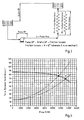
- Fig. 2 shows a typical hydraulic circuit, in which can be seen that the ⁇ p of the circuit is equal to the sum of two components:
- the new step is the application of the above theory to the MSF desalination plants minimizing the negative impact on both their efficiency and their G.O.R. (Gained Output Ratio in kg of distillate / kg of steam).
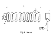
- Fig. 5 the schematic diagram of a MSF desalination unit according to the state of the art is shown. It comprises a brine heater 1, a desalination zone of multi-stage flash (MSF) distillation stages 2 being referred to as a heat recovery section 3, a heat rejection section 4 and (as an option) a deaerator 5, wherein the a desalination zone comprises for condensing the steam and winning the distillate.
- MSF multi-stage flash
- Sea water is pumped through a line 6 by a pump 7 into the heat rejection section 4, and further fed as 'make-up' via line 8 into the deaerator 5.
- the concentrated brine is discharged via line 9.
- the stream of brine and fresh sea-water is racked via line 10 by the brine recirculating pump 11 into the heat recovery section 3, cooling the different MSF distillation heat recovery stages 2.
- the brine is heated in the brine heater 1 and fed via line 12 back into the (most left) unit 2 of heat recovery section 3, and therefrom, in a reverse direction flow, into all other distillation stages 2.
- the brine heater 1 is heated by means of steam coming via a line 13 from a (non-illustrated) heat source.
- the condensate in the brine heater 1 is drawn off via line 14 by the pump 15.
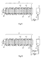
- the basic scope of the present invention is to provide a bypass line 22 bypassing the heat recovery section 3 as shown in Fig. 7 .
- an additional smaller pump 23 can be installed in parallel to the existing one, as illustrated in Fig. 8 .
- Fig. 11 shows another embodiment of the present invention, referring to the bypass line 22" of each single 'water box', wherein each bypass line 22' is arranged between the inlet and the outlet of the respective box.
- Another preferred embodiment of the present invention shows that such a circuit can include an additional brine re-circulating pump 23", as can be seen in Fig. 12 .
- the present invention is not limited to the thermodynamic optimization of the plant.
Landscapes
- Chemical & Material Sciences (AREA)
- Chemical Kinetics & Catalysis (AREA)
- Life Sciences & Earth Sciences (AREA)
- Hydrology & Water Resources (AREA)
- Engineering & Computer Science (AREA)
- Environmental & Geological Engineering (AREA)
- Water Supply & Treatment (AREA)
- Organic Chemistry (AREA)
- Heat Treatment Of Water, Waste Water Or Sewage (AREA)
- Vaporization, Distillation, Condensation, Sublimation, And Cold Traps (AREA)
Claims (10)
- Procédé de désalinisation de l'eau salée à l'aide d'au moins un réchauffeur de saumure, une zone de désalinisation d'unités de distillation à système flash (MSF) et au moins un désaérateur séparé, où l'eau de mer est désaérée et est pompée comme saumure de recirculation dans une partie de récupération de chaleur, où la saumure évaporée est condensée et le distillat est récupéré, caractérisé en ce que la partie de récupération de chaleur est au moins partiellement contournée par une partie de la saumure en recirculation, où ladite partie de la saumure en recirculation entre dans le réchauffeur de saumure.
- Procédé selon la revendication 1, caractérisé en ce que l'écoulement du contournement est varié pour contrôler le débit de la saumure contournée.
- Installation de désalinisation de l'eau salée avec au moins un réchauffeur de saumure (1), une zone de désalinisation d'unités de distillation à système flash (MSF) (2) et au moins un désaérateur (5), où la zone de désalinisation comprend une partie de récupération de chaleur (3) pour condenser la saumure évaporée et obtenir le distillat, caractérisée par au moins une conduite de contournement (22), évitant au moins une partie de la partie de récupération de chaleur (3) et entrant dans le réchauffeur de saumure (1).
- Installation selon la revendication 3, caractérisée par plusieurs conduites de contournement entre les différentes unités de distillation (2).
- Installation selon la revendication 4, caractérisée en ce que les différentes conduites de contournement (22') sont disposées entre les étapes adjacentes de distillation (2).
- Installation selon la revendication 4, caractérisée par une conduite de contournement (22") pour chaque étape de distillation (2).
- Installation selon l'une quelconque des revendications 3 à 6, caractérisée par une pompe supplémentaire (23, 23', 23" ) pour le saumure en recirculation.
- Installation selon l'une quelconque des revendications 3 à 7, caractérisée en ce qu'au moins une conduite de contournement consiste en un tube, dont le diamètre interne est variable pour modifier l'écoulement de la saumure en recirculation.
- Installation selon la revendication 8, caractérisée par au moins une vanne pour modifier l'écoulement de la saumure en recirculation.
- Installation selon la revendication 8, caractérisée par au moins une plaque perforée pour modifier l'écoulement de la saumure en recirculation.
Applications Claiming Priority (2)
| Application Number | Priority Date | Filing Date | Title |
|---|---|---|---|
| DE102008004106A DE102008004106A1 (de) | 2008-01-11 | 2008-01-11 | Verfahren und Anlage zur Entsalzung von Salzwasser unter Verwendung von MSF-Entsalzungseinheiten mit einem verbesserten Soleumlaufsystem |
| PCT/EP2009/050256 WO2009087234A1 (fr) | 2008-01-11 | 2009-01-12 | Procédé et usine de dessalement de l'eau salée au moyen d'unités de dessalement par détentes sucessives pourvues d'un système amélioré de recyclage de la saumure |
Publications (3)
| Publication Number | Publication Date |
|---|---|
| EP2242553A1 EP2242553A1 (fr) | 2010-10-27 |
| EP2242553B1 true EP2242553B1 (fr) | 2013-03-13 |
| EP2242553B9 EP2242553B9 (fr) | 2013-06-12 |
Family
ID=40456693
Family Applications (1)
| Application Number | Title | Priority Date | Filing Date |
|---|---|---|---|
| EP09701400.5A Not-in-force EP2242553B9 (fr) | 2008-01-11 | 2009-01-12 | Procédé et usine de dessalement de l'eau salée au moyen d'unités de dessalement par détentes sucessives pourvues d'un système amélioré de recyclage de la saumure |
Country Status (8)
| Country | Link |
|---|---|
| EP (1) | EP2242553B9 (fr) |
| JP (1) | JP5497663B2 (fr) |
| KR (1) | KR20100109551A (fr) |
| DE (1) | DE102008004106A1 (fr) |
| EG (1) | EG26735A (fr) |
| MA (1) | MA32068B1 (fr) |
| TN (1) | TN2010000281A1 (fr) |
| WO (1) | WO2009087234A1 (fr) |
Cited By (1)
| Publication number | Priority date | Publication date | Assignee | Title |
|---|---|---|---|---|
| WO2021223067A1 (fr) * | 2020-05-05 | 2021-11-11 | 鹏辰新材料科技股份有限公司 | Bouilloire réacteur de séparation de durène |
Families Citing this family (2)
| Publication number | Priority date | Publication date | Assignee | Title |
|---|---|---|---|---|
| CN101948148B (zh) * | 2010-10-22 | 2012-06-27 | 河北宏润重工股份有限公司 | 一种节能低温多效海水淡化装置 |
| CN103288157B (zh) * | 2012-02-24 | 2014-11-26 | 珠海格力电器股份有限公司 | 海水淡化装置 |
Family Cites Families (19)
| Publication number | Priority date | Publication date | Assignee | Title |
|---|---|---|---|---|
| US3312601A (en) | 1964-07-21 | 1967-04-04 | Allis Chalmers Mfg Co | Water immiscible liquid condenser in multistage flash distillation |
| US3431179A (en) | 1965-12-21 | 1969-03-04 | Applied Research & Eng Ltd | Distilland by-pass means multi-stage evaporators having |
| US3489652A (en) | 1966-04-18 | 1970-01-13 | American Mach & Foundry | Desalination process by multi-effect,multi-stage flash distillation combined with power generation |
| US3476654A (en) * | 1967-09-29 | 1969-11-04 | Us Interior | Multistage flash distillation with scale removal |
| FR1557110A (fr) * | 1967-12-22 | 1969-02-14 | ||
| US3692634A (en) * | 1970-05-07 | 1972-09-19 | Donald F Othmer | Method for producing pure water from sea water and other solutions by flash vaporization and condensation |
| US3734835A (en) | 1971-07-29 | 1973-05-22 | A Spicacci | Multi-stage flash distillation process |
| GB1434010A (en) * | 1972-04-21 | 1976-04-28 | Atomic Energy Authority Uk | Multistage evaporators |
| DE2850104A1 (de) * | 1978-11-18 | 1980-05-22 | Goldschmidt Ag Th | Verfahren zur direkten erwaermung eines fluessigen mediums unter ausnutzung der kondensationswaerme sowie vorrichtung zur durchfuehrung des verfahrens |
| JPS55111889A (en) * | 1979-02-21 | 1980-08-28 | Babcock Hitachi Kk | Multistage flash type water making apparatus |
| JPS57180478A (en) * | 1981-04-28 | 1982-11-06 | Ishikawajima Harima Heavy Ind Co Ltd | Method for converting sea water to fresh water |
| JPS59169591A (ja) * | 1983-03-17 | 1984-09-25 | Mitsubishi Heavy Ind Ltd | 多段フラツシユ型造水装置 |
| JPS6227089A (ja) * | 1985-07-25 | 1987-02-05 | Mitsubishi Heavy Ind Ltd | 多段フラツシユ型造水装置 |
| JPS6279593U (fr) * | 1985-11-05 | 1987-05-21 | ||
| JPS62262791A (ja) * | 1986-05-09 | 1987-11-14 | Hitachi Ltd | 多段蒸発式海水淡水化装置で生成する淡水の飲料水化方法 |
| JPS62187695U (fr) * | 1986-05-16 | 1987-11-28 | ||
| DZ3474A1 (fr) | 2000-10-21 | 2002-04-25 | Pb Power Ltd | Procede et materiel pour le dessalement de l eau base sur la methode de plateau de fractionnement. |
| US7255012B2 (en) * | 2004-12-01 | 2007-08-14 | Rosemount Inc. | Process fluid flow device with variable orifice |
| WO2006095397A1 (fr) * | 2005-03-07 | 2006-09-14 | Hitachi Zosen Corporation | Systeme de dessalement multi-etage de type encastre |
-
2008
- 2008-01-11 DE DE102008004106A patent/DE102008004106A1/de not_active Ceased
-
2009
- 2009-01-12 KR KR1020107015440A patent/KR20100109551A/ko not_active Abandoned
- 2009-01-12 WO PCT/EP2009/050256 patent/WO2009087234A1/fr not_active Ceased
- 2009-01-12 JP JP2010541798A patent/JP5497663B2/ja not_active Expired - Fee Related
- 2009-01-12 EP EP09701400.5A patent/EP2242553B9/fr not_active Not-in-force
-
2010
- 2010-06-17 TN TN2010000281A patent/TN2010000281A1/fr unknown
- 2010-07-11 EG EG2010071174A patent/EG26735A/en active
- 2010-08-09 MA MA33071A patent/MA32068B1/fr unknown
Cited By (1)
| Publication number | Priority date | Publication date | Assignee | Title |
|---|---|---|---|---|
| WO2021223067A1 (fr) * | 2020-05-05 | 2021-11-11 | 鹏辰新材料科技股份有限公司 | Bouilloire réacteur de séparation de durène |
Also Published As
| Publication number | Publication date |
|---|---|
| JP5497663B2 (ja) | 2014-05-21 |
| MA32068B1 (fr) | 2011-02-01 |
| EP2242553A1 (fr) | 2010-10-27 |
| EP2242553B9 (fr) | 2013-06-12 |
| EG26735A (en) | 2014-07-06 |
| KR20100109551A (ko) | 2010-10-08 |
| DE102008004106A9 (de) | 2009-12-17 |
| DE102008004106A1 (de) | 2009-09-10 |
| WO2009087234A1 (fr) | 2009-07-16 |
| TN2010000281A1 (en) | 2011-11-11 |
| JP2011509181A (ja) | 2011-03-24 |
Similar Documents
| Publication | Publication Date | Title |
|---|---|---|
| US8277614B2 (en) | Multi-stage flash desalination plant with feed cooler | |
| US20120067046A1 (en) | Power plant with co2 capture and water treatment plant | |
| US10850210B2 (en) | Production water desalinization via a reciprocal heat transfer and recovery | |
| US9393502B1 (en) | Desalination system | |
| CA2861670C (fr) | Procede et appareil pour le recyclage de l'eau | |
| EA004968B1 (ru) | Способ и устройство для опреснения воды путем многоступенчатого мгновенного испарения | |
| US20130264185A1 (en) | Method and Means of Production Water Desalination | |
| EP1781390B1 (fr) | Procede de dessalinisation entraine par distillat msf et appareil | |
| EP2242553B1 (fr) | Procédé et usine de dessalement de l'eau salée au moyen d'unités de dessalement par détentes sucessives pourvues d'un système amélioré de recyclage de la saumure | |
| FI122534B (fi) | Järjestely mustalipeän haihduttamiseksi | |
| Alotaibi et al. | Energy and exergy analysis of three major recirculating multi-stage flashing desalination plants in Kuwait | |
| Helal et al. | Enhancement of existing MSF plant productivity through design modification and change of operating conditions | |
| US3433717A (en) | Multistage flash still with vapor compression plant | |
| WO2017158399A1 (fr) | Système de purification d'eau thermique et procédé de fonctionnement dudit système | |
| EP2229229B1 (fr) | Procédé et usine de dessalement de l'eau de mer utilisant des unités de dessalement par détentes successives pourvues d'un système de recyclage de la vapeur | |
| Darwish | Thermal desalination in GCC and possible development | |
| CN1791556B (zh) | 水处理的方法和设备 | |
| GB2413321A (en) | Process and plant for multi-stage flash desalination of water | |
| JP4261438B2 (ja) | 発電及び海水淡水化システム | |
| WO2014194350A1 (fr) | Système de tour de refroidissement | |
| KR101567655B1 (ko) | Tvc-med의 비응축가스 벤팅구조 | |
| JP2025160825A (ja) | 海水淡水化・塩分製造プラント | |
| CN85104354A (zh) | 从含盐的原水制造蒸汽的蒸汽动力设备 | |
| Asgari et al. | The simulation of a multistage brine concentration process with vertical falling film evaporation | |
| JPS62110702A (ja) | 2段圧縮式ヒ−トポンプ |
Legal Events
| Date | Code | Title | Description |
|---|---|---|---|
| PUAI | Public reference made under article 153(3) epc to a published international application that has entered the european phase |
Free format text: ORIGINAL CODE: 0009012 |
|
| 17P | Request for examination filed |
Effective date: 20100608 |
|
| AK | Designated contracting states |
Kind code of ref document: A1 Designated state(s): AT BE BG CH CY CZ DE DK EE ES FI FR GB GR HR HU IE IS IT LI LT LU LV MC MK MT NL NO PL PT RO SE SI SK TR |
|
| AX | Request for extension of the european patent |
Extension state: AL BA RS |
|
| DAX | Request for extension of the european patent (deleted) | ||
| 17Q | First examination report despatched |
Effective date: 20110818 |
|
| GRAP | Despatch of communication of intention to grant a patent |
Free format text: ORIGINAL CODE: EPIDOSNIGR1 |
|
| GRAC | Information related to communication of intention to grant a patent modified |
Free format text: ORIGINAL CODE: EPIDOSCIGR1 |
|
| GRAC | Information related to communication of intention to grant a patent modified |
Free format text: ORIGINAL CODE: EPIDOSCIGR1 |
|
| GRAS | Grant fee paid |
Free format text: ORIGINAL CODE: EPIDOSNIGR3 |
|
| GRAP | Despatch of communication of intention to grant a patent |
Free format text: ORIGINAL CODE: EPIDOSNIGR1 |
|
| GRAA | (expected) grant |
Free format text: ORIGINAL CODE: 0009210 |
|
| AK | Designated contracting states |
Kind code of ref document: B1 Designated state(s): AT BE BG CH CY CZ DE DK EE ES FI FR GB GR HR HU IE IS IT LI LT LU LV MC MK MT NL NO PL PT RO SE SI SK TR |
|
| REG | Reference to a national code |
Ref country code: GB Ref legal event code: FG4D |
|
| REG | Reference to a national code |
Ref country code: CH Ref legal event code: EP Ref country code: AT Ref legal event code: REF Ref document number: 600434 Country of ref document: AT Kind code of ref document: T Effective date: 20130315 |
|
| REG | Reference to a national code |
Ref country code: IE Ref legal event code: FG4D |
|
| REG | Reference to a national code |
Ref country code: DE Ref legal event code: R096 Ref document number: 602009013871 Country of ref document: DE Effective date: 20130508 |
|
| REG | Reference to a national code |
Ref country code: DE Ref legal event code: R081 Ref document number: 602009013871 Country of ref document: DE Owner name: BABCOCK BORSIG STEINMUELLER GMBH, DE Free format text: FORMER OWNER: BABCOCK BORSIG SERVICE GMBH, 46049 OBERHAUSEN, DE Effective date: 20130419 |
|
| RAP2 | Party data changed (patent owner data changed or rights of a patent transferred) |
Owner name: BABCOCK BORSIG STEINMUELLER GMBH |
|
| PG25 | Lapsed in a contracting state [announced via postgrant information from national office to epo] |
Ref country code: LT Free format text: LAPSE BECAUSE OF FAILURE TO SUBMIT A TRANSLATION OF THE DESCRIPTION OR TO PAY THE FEE WITHIN THE PRESCRIBED TIME-LIMIT Effective date: 20130313 Ref country code: NO Free format text: LAPSE BECAUSE OF FAILURE TO SUBMIT A TRANSLATION OF THE DESCRIPTION OR TO PAY THE FEE WITHIN THE PRESCRIBED TIME-LIMIT Effective date: 20130613 Ref country code: BG Free format text: LAPSE BECAUSE OF FAILURE TO SUBMIT A TRANSLATION OF THE DESCRIPTION OR TO PAY THE FEE WITHIN THE PRESCRIBED TIME-LIMIT Effective date: 20130613 Ref country code: SE Free format text: LAPSE BECAUSE OF FAILURE TO SUBMIT A TRANSLATION OF THE DESCRIPTION OR TO PAY THE FEE WITHIN THE PRESCRIBED TIME-LIMIT Effective date: 20130313 Ref country code: ES Free format text: LAPSE BECAUSE OF FAILURE TO SUBMIT A TRANSLATION OF THE DESCRIPTION OR TO PAY THE FEE WITHIN THE PRESCRIBED TIME-LIMIT Effective date: 20130624 |
|
| REG | Reference to a national code |
Ref country code: AT Ref legal event code: MK05 Ref document number: 600434 Country of ref document: AT Kind code of ref document: T Effective date: 20130313 |
|
| REG | Reference to a national code |
Ref country code: NL Ref legal event code: VDEP Effective date: 20130313 |
|
| REG | Reference to a national code |
Ref country code: LT Ref legal event code: MG4D |
|
| PG25 | Lapsed in a contracting state [announced via postgrant information from national office to epo] |
Ref country code: GR Free format text: LAPSE BECAUSE OF FAILURE TO SUBMIT A TRANSLATION OF THE DESCRIPTION OR TO PAY THE FEE WITHIN THE PRESCRIBED TIME-LIMIT Effective date: 20130614 Ref country code: SI Free format text: LAPSE BECAUSE OF FAILURE TO SUBMIT A TRANSLATION OF THE DESCRIPTION OR TO PAY THE FEE WITHIN THE PRESCRIBED TIME-LIMIT Effective date: 20130313 Ref country code: LV Free format text: LAPSE BECAUSE OF FAILURE TO SUBMIT A TRANSLATION OF THE DESCRIPTION OR TO PAY THE FEE WITHIN THE PRESCRIBED TIME-LIMIT Effective date: 20130313 Ref country code: FI Free format text: LAPSE BECAUSE OF FAILURE TO SUBMIT A TRANSLATION OF THE DESCRIPTION OR TO PAY THE FEE WITHIN THE PRESCRIBED TIME-LIMIT Effective date: 20130313 |
|
| PG25 | Lapsed in a contracting state [announced via postgrant information from national office to epo] |
Ref country code: HR Free format text: LAPSE BECAUSE OF FAILURE TO SUBMIT A TRANSLATION OF THE DESCRIPTION OR TO PAY THE FEE WITHIN THE PRESCRIBED TIME-LIMIT Effective date: 20130313 Ref country code: BE Free format text: LAPSE BECAUSE OF FAILURE TO SUBMIT A TRANSLATION OF THE DESCRIPTION OR TO PAY THE FEE WITHIN THE PRESCRIBED TIME-LIMIT Effective date: 20130313 |
|
| PG25 | Lapsed in a contracting state [announced via postgrant information from national office to epo] |
Ref country code: EE Free format text: LAPSE BECAUSE OF FAILURE TO SUBMIT A TRANSLATION OF THE DESCRIPTION OR TO PAY THE FEE WITHIN THE PRESCRIBED TIME-LIMIT Effective date: 20130313 Ref country code: IS Free format text: LAPSE BECAUSE OF FAILURE TO SUBMIT A TRANSLATION OF THE DESCRIPTION OR TO PAY THE FEE WITHIN THE PRESCRIBED TIME-LIMIT Effective date: 20130713 Ref country code: SK Free format text: LAPSE BECAUSE OF FAILURE TO SUBMIT A TRANSLATION OF THE DESCRIPTION OR TO PAY THE FEE WITHIN THE PRESCRIBED TIME-LIMIT Effective date: 20130313 Ref country code: CZ Free format text: LAPSE BECAUSE OF FAILURE TO SUBMIT A TRANSLATION OF THE DESCRIPTION OR TO PAY THE FEE WITHIN THE PRESCRIBED TIME-LIMIT Effective date: 20130313 Ref country code: NL Free format text: LAPSE BECAUSE OF FAILURE TO SUBMIT A TRANSLATION OF THE DESCRIPTION OR TO PAY THE FEE WITHIN THE PRESCRIBED TIME-LIMIT Effective date: 20130313 Ref country code: PT Free format text: LAPSE BECAUSE OF FAILURE TO SUBMIT A TRANSLATION OF THE DESCRIPTION OR TO PAY THE FEE WITHIN THE PRESCRIBED TIME-LIMIT Effective date: 20130715 Ref country code: RO Free format text: LAPSE BECAUSE OF FAILURE TO SUBMIT A TRANSLATION OF THE DESCRIPTION OR TO PAY THE FEE WITHIN THE PRESCRIBED TIME-LIMIT Effective date: 20130313 Ref country code: AT Free format text: LAPSE BECAUSE OF FAILURE TO SUBMIT A TRANSLATION OF THE DESCRIPTION OR TO PAY THE FEE WITHIN THE PRESCRIBED TIME-LIMIT Effective date: 20130313 |
|
| PG25 | Lapsed in a contracting state [announced via postgrant information from national office to epo] |
Ref country code: PL Free format text: LAPSE BECAUSE OF FAILURE TO SUBMIT A TRANSLATION OF THE DESCRIPTION OR TO PAY THE FEE WITHIN THE PRESCRIBED TIME-LIMIT Effective date: 20130313 Ref country code: CY Free format text: LAPSE BECAUSE OF FAILURE TO SUBMIT A TRANSLATION OF THE DESCRIPTION OR TO PAY THE FEE WITHIN THE PRESCRIBED TIME-LIMIT Effective date: 20130313 |
|
| PG25 | Lapsed in a contracting state [announced via postgrant information from national office to epo] |
Ref country code: IT Free format text: LAPSE BECAUSE OF NON-PAYMENT OF DUE FEES Effective date: 20130112 |
|
| PLBE | No opposition filed within time limit |
Free format text: ORIGINAL CODE: 0009261 |
|
| STAA | Information on the status of an ep patent application or granted ep patent |
Free format text: STATUS: NO OPPOSITION FILED WITHIN TIME LIMIT |
|
| PG25 | Lapsed in a contracting state [announced via postgrant information from national office to epo] |
Ref country code: DK Free format text: LAPSE BECAUSE OF FAILURE TO SUBMIT A TRANSLATION OF THE DESCRIPTION OR TO PAY THE FEE WITHIN THE PRESCRIBED TIME-LIMIT Effective date: 20130313 |
|
| 26N | No opposition filed |
Effective date: 20131216 |
|
| REG | Reference to a national code |
Ref country code: DE Ref legal event code: R097 Ref document number: 602009013871 Country of ref document: DE Effective date: 20131216 |
|
| PGFP | Annual fee paid to national office [announced via postgrant information from national office to epo] |
Ref country code: DE Payment date: 20140122 Year of fee payment: 6 |
|
| PGFP | Annual fee paid to national office [announced via postgrant information from national office to epo] |
Ref country code: IT Payment date: 20140124 Year of fee payment: 6 Ref country code: FR Payment date: 20140122 Year of fee payment: 6 |
|
| PG25 | Lapsed in a contracting state [announced via postgrant information from national office to epo] |
Ref country code: LU Free format text: LAPSE BECAUSE OF FAILURE TO SUBMIT A TRANSLATION OF THE DESCRIPTION OR TO PAY THE FEE WITHIN THE PRESCRIBED TIME-LIMIT Effective date: 20140112 Ref country code: MC Free format text: LAPSE BECAUSE OF FAILURE TO SUBMIT A TRANSLATION OF THE DESCRIPTION OR TO PAY THE FEE WITHIN THE PRESCRIBED TIME-LIMIT Effective date: 20130313 |
|
| REG | Reference to a national code |
Ref country code: CH Ref legal event code: PL |
|
| GBPC | Gb: european patent ceased through non-payment of renewal fee |
Effective date: 20140112 |
|
| PG25 | Lapsed in a contracting state [announced via postgrant information from national office to epo] |
Ref country code: CH Free format text: LAPSE BECAUSE OF NON-PAYMENT OF DUE FEES Effective date: 20140131 Ref country code: LI Free format text: LAPSE BECAUSE OF NON-PAYMENT OF DUE FEES Effective date: 20140131 |
|
| REG | Reference to a national code |
Ref country code: IE Ref legal event code: MM4A |
|
| PG25 | Lapsed in a contracting state [announced via postgrant information from national office to epo] |
Ref country code: GB Free format text: LAPSE BECAUSE OF NON-PAYMENT OF DUE FEES Effective date: 20140112 |
|
| PG25 | Lapsed in a contracting state [announced via postgrant information from national office to epo] |
Ref country code: IE Free format text: LAPSE BECAUSE OF NON-PAYMENT OF DUE FEES Effective date: 20140112 |
|
| REG | Reference to a national code |
Ref country code: DE Ref legal event code: R119 Ref document number: 602009013871 Country of ref document: DE |
|
| PG25 | Lapsed in a contracting state [announced via postgrant information from national office to epo] |
Ref country code: DE Free format text: LAPSE BECAUSE OF NON-PAYMENT OF DUE FEES Effective date: 20150801 |
|
| REG | Reference to a national code |
Ref country code: FR Ref legal event code: ST Effective date: 20150930 |
|
| PG25 | Lapsed in a contracting state [announced via postgrant information from national office to epo] |
Ref country code: FR Free format text: LAPSE BECAUSE OF NON-PAYMENT OF DUE FEES Effective date: 20150202 |
|
| PG25 | Lapsed in a contracting state [announced via postgrant information from national office to epo] |
Ref country code: IT Free format text: LAPSE BECAUSE OF NON-PAYMENT OF DUE FEES Effective date: 20150112 |
|
| PG25 | Lapsed in a contracting state [announced via postgrant information from national office to epo] |
Ref country code: MT Free format text: LAPSE BECAUSE OF FAILURE TO SUBMIT A TRANSLATION OF THE DESCRIPTION OR TO PAY THE FEE WITHIN THE PRESCRIBED TIME-LIMIT Effective date: 20130313 |
|
| PG25 | Lapsed in a contracting state [announced via postgrant information from national office to epo] |
Ref country code: TR Free format text: LAPSE BECAUSE OF FAILURE TO SUBMIT A TRANSLATION OF THE DESCRIPTION OR TO PAY THE FEE WITHIN THE PRESCRIBED TIME-LIMIT Effective date: 20130313 Ref country code: HU Free format text: LAPSE BECAUSE OF FAILURE TO SUBMIT A TRANSLATION OF THE DESCRIPTION OR TO PAY THE FEE WITHIN THE PRESCRIBED TIME-LIMIT; INVALID AB INITIO Effective date: 20090112 |
|
| PG25 | Lapsed in a contracting state [announced via postgrant information from national office to epo] |
Ref country code: MK Free format text: LAPSE BECAUSE OF FAILURE TO SUBMIT A TRANSLATION OF THE DESCRIPTION OR TO PAY THE FEE WITHIN THE PRESCRIBED TIME-LIMIT Effective date: 20130313 |