EP1782526B1 - DISPOSITIF D'ALIMENTATION DE GROUPES AUXILIAIRES DESTINES A UN VEHICULE PROPULSÉ PAR COMBUSTIBLE OU ÉLECTRICITÉ& xA; - Google Patents
DISPOSITIF D'ALIMENTATION DE GROUPES AUXILIAIRES DESTINES A UN VEHICULE PROPULSÉ PAR COMBUSTIBLE OU ÉLECTRICITÉ& xA; Download PDFInfo
- Publication number
- EP1782526B1 EP1782526B1 EP05771357A EP05771357A EP1782526B1 EP 1782526 B1 EP1782526 B1 EP 1782526B1 EP 05771357 A EP05771357 A EP 05771357A EP 05771357 A EP05771357 A EP 05771357A EP 1782526 B1 EP1782526 B1 EP 1782526B1
- Authority
- EP
- European Patent Office
- Prior art keywords
- voltage
- rectifier
- connection
- circuit
- direct voltage
- Prior art date
- Legal status (The legal status is an assumption and is not a legal conclusion. Google has not performed a legal analysis and makes no representation as to the accuracy of the status listed.)
- Expired - Lifetime
Links
Images


Classifications
-
- H—ELECTRICITY
- H02—GENERATION; CONVERSION OR DISTRIBUTION OF ELECTRIC POWER
- H02M—APPARATUS FOR CONVERSION BETWEEN AC AND AC, BETWEEN AC AND DC, OR BETWEEN DC AND DC, AND FOR USE WITH MAINS OR SIMILAR POWER SUPPLY SYSTEMS; CONVERSION OF DC OR AC INPUT POWER INTO SURGE OUTPUT POWER; CONTROL OR REGULATION THEREOF
- H02M3/00—Conversion of DC power input into DC power output
- H02M3/02—Conversion of DC power input into DC power output without intermediate conversion into AC
- H02M3/04—Conversion of DC power input into DC power output without intermediate conversion into AC by static converters
- H02M3/10—Conversion of DC power input into DC power output without intermediate conversion into AC by static converters using discharge tubes with control electrode or semiconductor devices with control electrode
- H02M3/145—Conversion of DC power input into DC power output without intermediate conversion into AC by static converters using discharge tubes with control electrode or semiconductor devices with control electrode using devices of a triode or transistor type requiring continuous application of a control signal
- H02M3/155—Conversion of DC power input into DC power output without intermediate conversion into AC by static converters using discharge tubes with control electrode or semiconductor devices with control electrode using devices of a triode or transistor type requiring continuous application of a control signal using semiconductor devices only
- H02M3/156—Conversion of DC power input into DC power output without intermediate conversion into AC by static converters using discharge tubes with control electrode or semiconductor devices with control electrode using devices of a triode or transistor type requiring continuous application of a control signal using semiconductor devices only with automatic control of output voltage or current, e.g. switching regulators
- H02M3/158—Conversion of DC power input into DC power output without intermediate conversion into AC by static converters using discharge tubes with control electrode or semiconductor devices with control electrode using devices of a triode or transistor type requiring continuous application of a control signal using semiconductor devices only with automatic control of output voltage or current, e.g. switching regulators including plural semiconductor devices as final control devices for a single load
- H02M3/1584—Conversion of DC power input into DC power output without intermediate conversion into AC by static converters using discharge tubes with control electrode or semiconductor devices with control electrode using devices of a triode or transistor type requiring continuous application of a control signal using semiconductor devices only with automatic control of output voltage or current, e.g. switching regulators including plural semiconductor devices as final control devices for a single load with a plurality of power processing stages connected in parallel
-
- B—PERFORMING OPERATIONS; TRANSPORTING
- B60—VEHICLES IN GENERAL
- B60L—PROPULSION OF ELECTRICALLY-PROPELLED VEHICLES; SUPPLYING ELECTRIC POWER FOR AUXILIARY EQUIPMENT OF ELECTRICALLY-PROPELLED VEHICLES; ELECTRODYNAMIC BRAKE SYSTEMS FOR VEHICLES IN GENERAL; MAGNETIC SUSPENSION OR LEVITATION FOR VEHICLES; MONITORING OPERATING VARIABLES OF ELECTRICALLY-PROPELLED VEHICLES; ELECTRIC SAFETY DEVICES FOR ELECTRICALLY-PROPELLED VEHICLES
- B60L50/00—Electric propulsion with power supplied within the vehicle
- B60L50/10—Electric propulsion with power supplied within the vehicle using propulsion power supplied by engine-driven generators, e.g. generators driven by combustion engines
- B60L50/15—Electric propulsion with power supplied within the vehicle using propulsion power supplied by engine-driven generators, e.g. generators driven by combustion engines with additional electric power supply
-
- H—ELECTRICITY
- H02—GENERATION; CONVERSION OR DISTRIBUTION OF ELECTRIC POWER
- H02M—APPARATUS FOR CONVERSION BETWEEN AC AND AC, BETWEEN AC AND DC, OR BETWEEN DC AND DC, AND FOR USE WITH MAINS OR SIMILAR POWER SUPPLY SYSTEMS; CONVERSION OF DC OR AC INPUT POWER INTO SURGE OUTPUT POWER; CONTROL OR REGULATION THEREOF
- H02M3/00—Conversion of DC power input into DC power output
- H02M3/02—Conversion of DC power input into DC power output without intermediate conversion into AC
- H02M3/04—Conversion of DC power input into DC power output without intermediate conversion into AC by static converters
- H02M3/10—Conversion of DC power input into DC power output without intermediate conversion into AC by static converters using discharge tubes with control electrode or semiconductor devices with control electrode
- H02M3/145—Conversion of DC power input into DC power output without intermediate conversion into AC by static converters using discharge tubes with control electrode or semiconductor devices with control electrode using devices of a triode or transistor type requiring continuous application of a control signal
- H02M3/155—Conversion of DC power input into DC power output without intermediate conversion into AC by static converters using discharge tubes with control electrode or semiconductor devices with control electrode using devices of a triode or transistor type requiring continuous application of a control signal using semiconductor devices only
- H02M3/156—Conversion of DC power input into DC power output without intermediate conversion into AC by static converters using discharge tubes with control electrode or semiconductor devices with control electrode using devices of a triode or transistor type requiring continuous application of a control signal using semiconductor devices only with automatic control of output voltage or current, e.g. switching regulators
- H02M3/158—Conversion of DC power input into DC power output without intermediate conversion into AC by static converters using discharge tubes with control electrode or semiconductor devices with control electrode using devices of a triode or transistor type requiring continuous application of a control signal using semiconductor devices only with automatic control of output voltage or current, e.g. switching regulators including plural semiconductor devices as final control devices for a single load
-
- B—PERFORMING OPERATIONS; TRANSPORTING
- B60—VEHICLES IN GENERAL
- B60L—PROPULSION OF ELECTRICALLY-PROPELLED VEHICLES; SUPPLYING ELECTRIC POWER FOR AUXILIARY EQUIPMENT OF ELECTRICALLY-PROPELLED VEHICLES; ELECTRODYNAMIC BRAKE SYSTEMS FOR VEHICLES IN GENERAL; MAGNETIC SUSPENSION OR LEVITATION FOR VEHICLES; MONITORING OPERATING VARIABLES OF ELECTRICALLY-PROPELLED VEHICLES; ELECTRIC SAFETY DEVICES FOR ELECTRICALLY-PROPELLED VEHICLES
- B60L2200/00—Type of vehicles
- B60L2200/26—Rail vehicles
-
- B—PERFORMING OPERATIONS; TRANSPORTING
- B60—VEHICLES IN GENERAL
- B60L—PROPULSION OF ELECTRICALLY-PROPELLED VEHICLES; SUPPLYING ELECTRIC POWER FOR AUXILIARY EQUIPMENT OF ELECTRICALLY-PROPELLED VEHICLES; ELECTRODYNAMIC BRAKE SYSTEMS FOR VEHICLES IN GENERAL; MAGNETIC SUSPENSION OR LEVITATION FOR VEHICLES; MONITORING OPERATING VARIABLES OF ELECTRICALLY-PROPELLED VEHICLES; ELECTRIC SAFETY DEVICES FOR ELECTRICALLY-PROPELLED VEHICLES
- B60L2210/00—Converter types
- B60L2210/10—DC to DC converters
- B60L2210/12—Buck converters
-
- Y—GENERAL TAGGING OF NEW TECHNOLOGICAL DEVELOPMENTS; GENERAL TAGGING OF CROSS-SECTIONAL TECHNOLOGIES SPANNING OVER SEVERAL SECTIONS OF THE IPC; TECHNICAL SUBJECTS COVERED BY FORMER USPC CROSS-REFERENCE ART COLLECTIONS [XRACs] AND DIGESTS
- Y02—TECHNOLOGIES OR APPLICATIONS FOR MITIGATION OR ADAPTATION AGAINST CLIMATE CHANGE
- Y02T—CLIMATE CHANGE MITIGATION TECHNOLOGIES RELATED TO TRANSPORTATION
- Y02T10/00—Road transport of goods or passengers
- Y02T10/60—Other road transportation technologies with climate change mitigation effect
- Y02T10/70—Energy storage systems for electromobility, e.g. batteries
-
- Y—GENERAL TAGGING OF NEW TECHNOLOGICAL DEVELOPMENTS; GENERAL TAGGING OF CROSS-SECTIONAL TECHNOLOGIES SPANNING OVER SEVERAL SECTIONS OF THE IPC; TECHNICAL SUBJECTS COVERED BY FORMER USPC CROSS-REFERENCE ART COLLECTIONS [XRACs] AND DIGESTS
- Y02—TECHNOLOGIES OR APPLICATIONS FOR MITIGATION OR ADAPTATION AGAINST CLIMATE CHANGE
- Y02T—CLIMATE CHANGE MITIGATION TECHNOLOGIES RELATED TO TRANSPORTATION
- Y02T10/00—Road transport of goods or passengers
- Y02T10/60—Other road transportation technologies with climate change mitigation effect
- Y02T10/7072—Electromobility specific charging systems or methods for batteries, ultracapacitors, supercapacitors or double-layer capacitors
-
- Y—GENERAL TAGGING OF NEW TECHNOLOGICAL DEVELOPMENTS; GENERAL TAGGING OF CROSS-SECTIONAL TECHNOLOGIES SPANNING OVER SEVERAL SECTIONS OF THE IPC; TECHNICAL SUBJECTS COVERED BY FORMER USPC CROSS-REFERENCE ART COLLECTIONS [XRACs] AND DIGESTS
- Y02—TECHNOLOGIES OR APPLICATIONS FOR MITIGATION OR ADAPTATION AGAINST CLIMATE CHANGE
- Y02T—CLIMATE CHANGE MITIGATION TECHNOLOGIES RELATED TO TRANSPORTATION
- Y02T10/00—Road transport of goods or passengers
- Y02T10/60—Other road transportation technologies with climate change mitigation effect
- Y02T10/72—Electric energy management in electromobility
Definitions
- the invention relates to the field of auxiliary equipment for fuel-electrically driven vehicles. It is based on a device for feeding auxiliary equipment for a fuel-electrically driven vehicle according to the preamble of the independent claims.
- auxiliary equipment for fuel-electrically driven vehicles are used today mainly in diesel-electric locomotives or large diesel-electric mining vehicles, the auxiliary equipment, as a fan, air conditioners, servomotors, auxiliary power converters, etc., are formed. Such auxiliary equipment is commonly fed by a suitable device.
- a suitable device for feeding auxiliary equipment for a fuel-electric vehicle is for example in the US 6,087,791 and in the DE 200 01 113 U1 specified.
- the device comprises an internal combustion engine, a generator driven by the internal combustion engine, and a rectifier connected to the generator on the alternating voltage side.
- the rectifier is connected on the DC voltage side to a first and a second terminal of a DC voltage circuit.
- a plurality of inverters are connected to the first and second terminals of the DC voltage circuit, which inverters each supply the corresponding auxiliary equipment device, such as fans, air conditioning, servo motor, auxiliary power converters, etc., with electrical energy.
- auxiliary equipment device such as fans, air conditioning, servo motor, auxiliary power converters, etc.
- drive inverter is also connected to the first and second terminals of the DC voltage circuit, which drive inverter feeds one or more traction motors of the vehicle on the AC voltage side.
- a second AC side connected to the generator rectifier is provided.
- the second rectifier is then connected on the DC voltage side to a first and a second terminal of a second DC voltage circuit, wherein a second drive inverter is connected to the first and second terminals of the second DC voltage circuit, which second drive inverter feeds one or more traction motors of the vehicle on the AC voltage side.
- the problem with the device for feeding auxiliary equipment for a fuel-electric vehicle of the US 6,087,791 and the DE 200 01 113 U1 is that the connected to the first and second terminal of the DC voltage circuit inverter must be designed for the above high DC voltage, ie that the power semiconductor switches of the respective inverter must have a high blocking capability and appropriate protection devices and specially adapted operating procedures.
- the structure of the inverter is thus very complicated, prone to failure and requires a lot of space.
- a device for supplying auxiliary equipment for a fuel-electrically driven vehicle comprises a first internal combustion engine and a first generator driven by the first internal combustion engine.
- a first rectifier associated with the first generator is connected, wherein the first rectifier, a first buck converter is connected downstream.
- An associated first DC voltage circuit is connected downstream of the first buck converter, to which first DC voltage circuit a first inverter is connected for supplying auxiliary equipment.
- the device of the DE 94 13 638 U1 a second internal combustion engine and a second generator driven by the second internal combustion engine.
- a second generator associated with the second rectifier On the AC side with the second generator, a second generator associated with the second rectifier is connected, wherein the second rectifier, a second buck converter is connected downstream.
- the second buck converter is followed by an associated second DC voltage circuit, with which second DC voltage circuit, a second inverter for feeding auxiliary equipment is connected.
- the object of the invention is therefore to provide a device for feeding auxiliary equipment for a fuel-electrically driven vehicle, which has a small footprint and is also robust and insensitive to interference. This object is solved by the features of claim 1 or claim 2. In the dependent claims advantageous developments of the invention are given.
- the inventive device for feeding auxiliary equipment for a fuel-electrically driven vehicle comprises an internal combustion engine, a single generator driven by the internal combustion engine and an alternating voltage side connected to the generator and the generator associated with the single rectifier, wherein the rectifier is connected on the DC side with a first and a second terminal of a rectifier associated and the rectifier downstream single DC voltage circuit.
- a first and a second buck converter is provided, wherein the first and second buck converter is connected to the first and second terminal of the DC circuit and the first and second buck converter is further connected to the first and second buck converter downstream common DC bus for feeding the auxiliary equipment , To the common DC voltage bus inverter of the auxiliary equipment and / or DC voltage controller of the auxiliary equipment are connected to the power supply.
- the voltage at the DC busbar can be set with advantage. This setting is made such that the voltage at the DC busbar is lower than the voltage between the first and second terminals of the DC voltage circuit.
- the insulation distance of the DC busbar i. the busbars of the DC busbar, be reduced, so that advantageously can be saved space and also the assembly and maintenance costs can be kept low.
- a redundant supply of DC voltage busbar is possible by the two connected to the common DC voltage buck converter bucking, i.
- the DC voltage supply is fed via the other step-down converter, so that the auxiliary device devices can continue to be supplied via their inverters and / or DC voltage controllers.
- the inventive device is characterized very robust, insensitive to interference and is characterized by a high availability.
- the inverters and / or DC voltage adjusters of the auxiliary operating devices ie the power semiconductor switches of the inverters and / or DC voltage adjusters with associated protective devices and operating methods, do not have to withstand the high voltage as known from the prior art of the DC circuit be designed, but only to the lower voltage of the DC busbar.
- the inverter and / or DC voltage controller are less sensitive to interference and require correspondingly little space.
- the simple and space-saving design of the inverter and / or DC voltage controller causes low installation and maintenance costs.
- a further AC voltage side connected to the single generator and the generator associated rectifier is provided, wherein the first buck converter and the further rectifier is connected to a the first buck converter and the other rectifier downstream common DC bus for feeding the auxiliary equipment.
- the voltage at the DC voltage busbar can also be set with advantage, as has already been explained in the solution with two buck converters.
- the isolation distance of the DC busbar i. the busbars of the DC busbar, be reduced, so that advantageously can be saved space and also the assembly and maintenance costs can be kept low.
- the first step-down converter and the other rectifier which are both connected to the common DC voltage busbar, a redundant supply of DC busbars possible, i.
- the DC voltage supply is fed via the rectifier, so that the auxiliary equipment can continue to be supplied via its inverters and / or DC voltage controllers.
- the inventive device is characterized very robust, insensitive to interference and is characterized by a high availability.
- the inverters and / or DC voltage adjusters of the auxiliary operating devices do not have to be, as known from the prior art, due to the lower voltage of the DC busbar compared to the DC voltage circuit. be designed for the high voltage of the DC circuit, but only to the lower voltage of the DC busbar.
- the inverter and / or DC voltage controller are less sensitive to interference and require correspondingly little space.
- the simple and space-saving design of the inverter and / or DC voltage controller causes low installation and maintenance costs.
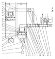
- Fig. 1 a first embodiment of the inventive device for feeding auxiliary equipment for a fuel-electric vehicle is shown.
- the device according to the invention Fig. 1 includes an internal combustion engine 1, a driven by the internal combustion engine 1 generator 2 and a voltage side connected to the generator 2 and the generator 2 associated rectifier 3, the rectifier 3 on the DC side with a first and a second terminal 5, 6 of the rectifier 3 and the rectifier 3 downstream DC voltage circuit 4 is connected.
- a first and a second buck converter 7, 8 are provided, the first and the second buck converter 7, 8 being respectively connected to the first and second terminals 5, 6 of the DC voltage circuit 4.
- Fig. 1 includes an internal combustion engine 1, a driven by the internal combustion engine 1 generator 2 and a voltage side connected to the generator 2 and the generator 2 associated rectifier 3, the rectifier 3 on the DC side with a first and a second terminal 5, 6 of the rectifier 3 and the rectifier 3 downstream DC voltage circuit 4 is connected.
- a first and a second buck converter 7, 8 are provided, the first and
- FIG. 1 represents the DC voltage circuit 4 with respect to the first and second buck converter 7, 8 in particular a common DC voltage circuit 4, wherein in particular the first and second buck converter 7, 8 is connected downstream of the DC voltage circuit 4. Furthermore, the first and second buck converters 7, 8 are connected to a common DC voltage bus 9 downstream of the first and second buck converters 7, 8 for supplying the auxiliary power equipment 10.
- Fig. 1 Inverter of auxiliary equipment 10 and / or DC voltage adjuster of the auxiliary operating devices 10 connected to the power supply.
- the voltage at the DC busbar 9 can be set with advantage. This setting is made such that the voltage at the DC voltage busbar 9 is lower than the voltage between the first and second terminals of the 5, 6 DC voltage circuit 4. Due to the lower compared to the DC voltage circuit 4 voltage of the DC busbar 9, the isolation distance of the busbars of the DC busbar 9, can be reduced, so that advantageously space can be saved and also the assembly and maintenance costs can be kept low or minimized. Furthermore, a redundant supply of DC voltage busbar 9 is possible by the two connected to the common DC voltage bus 9 buck converter 7, 8.
- the inventive device is characterized very robust, insensitive to interference and is characterized by a high availability.
- Fig. 1 is the respective buck converter 7, 8 formed by a series circuit of a drivable power semiconductor switch 11 with a diode 12 and by a parallel to the series circuit of the drivable power semiconductor switch 11 connected to the diode 12 capacitance 13.
- the controllable power semiconductor switch 11 is formed as a bipolar transistor with insulated gate electrode (IGBT).
- IGBT turn-off thyristor
- IGCT - Integrated Gate Commutated Thyristor an integrated thyristor with commutated drive electrode
- the controllable power semiconductor switch 11 is furthermore connected to the first terminal 5 of the DC voltage circuit 4 and the diode 12 is connected to the second terminal 6 of the DC voltage circuit 4.
- the diode 12 through a first connection 14 and the connection point of the diode 12 with the drivable power semiconductor switch 11 through a second connection 15 with the common DC busbar 9 connected.
- the respective buck converter 7, 8 thus comes with a minimum number of components and is thus very simple and space-saving feasible. Due to the small number of components of the first and second buck converter 7, 8 is particularly robust and resistant to interference and therefore has a high availability.
- a filter circuit 16 advantageously effects that unwanted voltage oscillations and current oscillations generated by switching operations of the respective buck converter 7, 8 are filtered out, so that the voltage of the DC busbar 9, ie the voltage present between the busbars, is almost a DC voltage.
- a second embodiment of the inventive device according to Fig. 2 is in contrast to the first embodiment according to Fig. 1 in the respective buck converter 7, 8 in the first connection 14 and in the second connection 15 each have a current direction limiting element 17 is turned on.
- the respective current-direction limiting element 17 serves to ensure that only one current flows in a defined current direction from the respective buck converter 7, 8 back to the DC voltage bus 9 and back again. This advantageously prevents a fault current, for example caused by faults in the DC busbar 9 and / or a fault in one or more auxiliary operating devices 10, from flowing back to the respective buck converter 7, 8 and causing damage or even destruction to the respective buck converter 7, 8.
- the respective current direction limiting element 17 is according to Fig. 2 preferably designed as a diode and thus advantageously very simple and space-saving feasible.
- a third embodiment of the inventive device according to Fig. 3 is different from the first and second embodiments Fig. 1 and Fig. 2 the respective buck converter 7, 8 by a first and a second series circuit 7a, 7b, 8a, 8b each of a controllable power semiconductor switch 11 a, 11 b formed with a diode 12a, 12b and by a parallel connected to each series circuit capacitance 13, wherein the Diode 12a of the first series circuit 7a, 8a is connected to the diode 12b of the second series circuit 7b, 8b.
- the controllable power semiconductor switch 11 a, 11 b as a bipolar transistor with insulated gate electrode (IGBT) is formed.
- IGBT insulated gate electrode
- controllable power semiconductor switch is designed as a power MOSFET, as a turn-off thyristor (GTO) or as an integrated thyristor with commutated drive electrode (IGCT - Integrated Gate Commutated Thyristor).
- GTO turn-off thyristor
- IGCT - Integrated Gate Commutated Thyristor an integrated thyristor with commutated drive electrode
- connection point of the diode 12a of the first series circuit 7a, 8a to the drivable power semiconductor switch 11a of the first series circuit 7a, 8a is connected to the common DC voltage bus 9 through a first connection 14.
- connection point of the diode 12b of the second series circuit 7b, 8b with the drivable power semiconductor switch 11b of the second series circuit 7b, 8b connected by a second connection 15 to the common DC busbar 9.
- the respective buck converter 7, 8 according to Fig. 3 also comes with a minimum number of components and is thus very simple and space-saving feasible. Due to the small number of components of the first and second buck converter 7, 8 is particularly robust and resistant to interference and therefore has a high availability.
- Fig. 3 is connected to the respective buck converter 7, 8 between the first connection 14 and the common DC voltage bus 9 and between the second connection 15 and the common DC voltage bus 9, a filter circuit 16.
- the filter circuit 16 advantageously effects that unwanted voltage oscillations and current oscillations generated by switching operations of the respective buck converter 7, 8 are filtered out, so that the voltage of the DC busbar 9, ie the voltage present between the busbars, is almost a DC voltage.
- a fourth embodiment of the inventive device according to Fig. 4 is different from the third embodiment according to Fig. 3 in the respective buck converter 7, 8 in the first connection 14 and in the second connection 15 each have a current direction limiting element 17 is turned on.
- the respective current-direction limiting element 17 serves to ensure that only one current flows in a defined current direction from the respective buck converter 7, 8 back to the DC voltage bus 9 and back again. This advantageously prevents a fault current, for example caused by a fault of the DC voltage bus 9 and / or an error in one or more auxiliary operation devices 10, from flowing back to the respective buck converter 7, 8 and damaging or even destroying the respective buck converter 7, 8 ,
- the respective current direction limiting element 17 is according to Fig. 4 preferably designed as a diode and thus advantageously very simple and space-saving feasible.
- a fifth and sixth embodiment of the inventive device according to Fig. 5 and Fig. 6 is alternative to the first, second, third and fourth embodiment according to Fig. 1 . Fig. 2 . Fig. 3 and Fig. 4 instead of the second buck converter 8, a further AC voltage side connected to the generator 2 rectifier 21 is provided, wherein the first buck converter 7 and another AC voltage side connected to the generator 2 and the generator 2 associated rectifier 21 with a first buck converter 7 and the other rectifier 21 downstream common DC voltage bus 9 is connected to the supply of auxiliary equipment 10.
- the first buck converter 7 in particular the DC voltage circuit 4 downstream.
- the first buck converter 7 is after Fig. 5 corresponding the first buck converter after Fig.
- the voltage at the DC voltage busbar 9 can be set with advantage. This setting is made such that the voltage at the DC voltage busbar 9 is lower than the voltage between the first and second terminals of the 5, 6 DC voltage circuit 4. Due to the lower compared to the DC voltage circuit 4 voltage of the DC busbar 9, the isolation distance of the busbars of the DC busbar 9, can be reduced, so that advantageously space can be saved and also the assembly and maintenance costs can be kept low or minimized. Furthermore, by the first buck converter 7 and the other rectifier 21, which are both connected to the common DC voltage bus 9, a redundant power supply of the DC busbar 9 possible.
- the power supply of the DC voltage bus 9 is effected via the further rectifier 21, so that the auxiliary power devices 10 can continue to be supplied via their inverters and / or DC voltage actuators.
- the inventive device is characterized very robust, insensitive to interference and is characterized by a high availability.
- Fig. 5 and Fig. 6 is in the further rectifier 21, as well as the first buck converter 7, in the first connection 14 and in the second connection 15 each have a current direction limiting element 17 is turned on.
- the respective current-direction limiting element 17 serves to ensure that only one current flows in a defined current direction from the first buck converter 7 or from the further rectifier 21 to the DC voltage bus 9 and back again. This advantageously prevents a fault current, for example caused by a fault of the DC voltage bus 9 and / or an error in one or more auxiliary operation devices 10, from flowing back to the first buck converter 7 or to the further rectifier 21 and the first buck converter 7 or the other Rectifier 21 damaged or even destroyed.
- the respective current direction limiting element 17 is according to Fig. 5 and Fig. 6 preferably designed as a diode and thus advantageously very simple and space-saving feasible.
- the separating element 20 is preferably designed as a low-inductance switch, for example as a mechanical or as a controllable power semiconductor switch, or as a fuse.
- the common DC voltage bus 9 has an overvoltage limiting network 18.
- the overvoltage limiting network 18 is formed by a resistor and a controllable switch, preferably a controllable power semiconductor switch, wherein the overvoltage limiting network 18 is actuated by closing the switch at an occurring overvoltage of the voltage of the DC busbar 9.
- the overvoltage limiting network 18 is actuated for a predetermined period of time. This period of time is preferably predetermined as a function of the thermal capacity of the resistor. The operation is carried out according to known to the expert criteria, which will not be discussed in detail at this point.
- a separator 20 is turned on. This advantageously ensures that the disturbed or failed buck converter 7, 8, the associated first and second connection 14, 15, for example, does not short-circuit.
- the separating element 20 is preferably low inductive Switch, designed for example as a mechanical or as a controllable power semiconductor switch, or as a backup.
- Fig. 7 . Fig. 8 . Fig. 9 and Fig. 10 are alternative to the first, second, third, fourth, fifth and sixth embodiments according to Fig. 1 . Fig. 2 . Fig. 3 . Fig. 4 . Fig. 5 and Fig.
- first and second rectifiers 3a, 3b are connected to the generator 2 on the alternating voltage side, the first rectifier 3a having a first and a second terminal 5a, 6a of the first rectifier 3a and the first rectifier circuit 3a connected downstream of the first rectifier 3a and the second rectifier 3b on the DC side with a first and a second terminal 5b, 6b of the second rectifier 3b associated and the second rectifier 3b downstream second DC voltage circuit 4b is connected.
- a first and a second buck converter 7, 8 is provided, wherein the first buck converter 7 to the first and second terminals 5a, 6a of the first DC voltage circuit 4a and the second buck converter 8 to the first and second terminals 5b, 6b of the second DC voltage circuit 4b connected is. Furthermore, the first and second buck converters 7, 8 are connected to a common DC voltage bus 9 downstream of the first and second buck converters 7, 8 for supplying the auxiliary power equipment 10. According to FIGS. 7 to 10 the first buck converter 7 is followed in particular by the first DC voltage circuit 4a and the second buck converter 8 in particular is connected downstream of the second DC voltage circuit 4b. According to Fig. 7 . Fig. 8 . Fig. 9 and Fig.
- Fig. 10 has the common DC voltage busbar 9 two of the busbars.
- To the common DC voltage busbar 9 are according to Fig. 7 . Fig. 8 .
- Fig. 9 and Fig. 10 Inverter of the auxiliary equipment 10 and / or DC voltage adjuster of the auxiliary equipment 10 connected to the power supply.
- the voltage at the DC busbar 9 can be set with advantage. This setting is made such that the voltage at the DC voltage busbar 9 is lower than the voltage between the first and second terminals 5a, 5b, 6a, 6b of the respective DC voltage circuit 4a, 4b.
- the isolation distance of the busbar strands of the DC busbar 9 can be reduced, so that advantageously space can be saved and also the assembly and maintenance costs can be kept low or minimized.
- a redundant supply of DC voltage busbar 9 is possible by the two connected to the common DC voltage bus 9 buck converter 7, 8.
- the DC voltage busbar 9 is fed via the second buck converter 8, so that the auxiliary power equipment 10 can continue to be supplied via its inverters and / or DC voltage actuators.
- the device is therefore very robust, insensitive to interference and characterized by a high availability.
- Fig. 7 . Fig. 8 . Fig. 9 and Fig. 10 is the respective buck converter 7, 8 formed by a series circuit of a drivable power semiconductor switch 11 with a diode 12 and by a parallel to the series circuit of the drivable power semiconductor switch 11 connected to the diode 12 capacitance 13.
- the controllable power semiconductor switch 11 is formed as a bipolar transistor with insulated gate electrode (IGBT).
- controllable power semiconductor switch is designed as a power MOSFET, as a turn-off thyristor (GTO) or as an integrated thyristor with commutated drive electrode (IGCT - Integrated Gate Commutated Thyristor).
- GTO turn-off thyristor
- IGCT - Integrated Gate Commutated Thyristor IGCT - Integrated Gate Commutated Thyristor
- the diode 12 is connected by a first connection 14 and the connection point of the diode 12 to the controllable power semiconductor switch 11 by a second connection 15 to the common DC voltage busbar 9.
- the respective buck converter 7, 8 thus comes with a minimum number of components and is thus very simple and space-saving feasible. Due to the small number of components of the first and second buck converter 7, 8 is particularly robust and resistant to interference and therefore has a high availability.
- the filter circuit 16 advantageously effects that unwanted voltage oscillations and current oscillations generated by switching operations of the respective buck converter 7, 8 are filtered out, so that the voltage of the DC busbar 9, ie the voltage present between the busbars, is almost a DC voltage.
- the eighth embodiment of the device according to Fig. 8 is in contrast to the seventh embodiment according to Fig. 7 in the respective buck converter 7, 8 in the first connection 14 and in the second connection 15 each have a current direction limiting element 17 is turned on.
- the respective current-direction limiting element 17 serves to ensure that only one current flows in a defined current direction from the respective buck converter 7, 8 back to the DC voltage bus 9 and back again. This advantageously prevents a fault current, for example caused by faults in the DC busbar 9 and / or a fault in one or more auxiliary operating devices 10, from flowing back to the respective buck converter 7, 8 and causing damage or even destruction to the respective buck converter 7, 8.
- the respective current direction limiting element 17 is according to Fig. 8 preferably designed as a diode and thus advantageously very simple and space-saving feasible.
- the respective step-down converter 7, 8 by a first and a second series circuit 7a, 7b, 8a, 8b each of a controllable power semiconductor switch 11a, 11b formed with a diode 12a, 12b and by a respective parallel connected to each series circuit capacitance 13, wherein the diode 12a of the first series circuit 7a, 8a is connected to the diode 12b of the second series circuit 7b, 8b.
- the controllable power semiconductor switch 11a, 11b is formed as a bipolar transistor with insulated gate electrode (IGBT).
- controllable power semiconductor switch is designed as a power MOSFET, as a turn-off thyristor (GTO) or as an integrated thyristor with commutated drive electrode (IGCT - Integrated Gate Commutated Thyristor).
- GTO turn-off thyristor
- IGCT - Integrated Gate Commutated Thyristor an integrated thyristor with commutated drive electrode
- the respective buck converter 7, 8 according to Fig. 9 also comes with a minimum number of components and is thus very simple and space-saving feasible. Due to the small number of components of the first and second buck converter 7, 8 is particularly robust and resistant to interference and therefore has a high availability.
- Fig. 9 is connected to the respective buck converter 7, 8 between the first connection 14 and the common DC voltage bus 9 and between the second connection 15 and the common DC voltage bus 9, a filter circuit 16.
- the filter circuit 16 advantageously causes by switching operations of the respective Tiefsetzstellers 7, 8 generated unwanted voltage oscillations and current oscillations are filtered out, so that the voltage of the DC busbar 9, ie, the voltage applied between the busbars, voltage is almost a DC voltage.
- the tenth embodiment of the device according to Fig. 10 is in contrast to the ninth embodiment according to Fig. 9 in the respective buck converter 7, 8 in the first connection 14 and in the second connection 15 each have a current direction limiting element 17 is turned on.
- the respective current-direction limiting element 17 serves to ensure that only one current flows in a defined current direction from the respective buck converter 7, 8 back to the DC voltage bus 9 and back again. This advantageously prevents a fault current, for example caused by a fault of the DC voltage bus 9 and / or an error in one or more auxiliary operation devices 10, from flowing back to the respective buck converter 7, 8 and damaging or even destroying the respective buck converter 7, 8 ,
- the respective current direction limiting element 17 is according to Fig. 10 preferably designed as a diode and thus advantageously very simple and space-saving feasible.
- the common DC voltage bus 9 has an overvoltage limiting network 18.
- the overvoltage limiting network 18 is formed by a resistor and a controllable switch, preferably a controllable power semiconductor switch, wherein the overvoltage limiting network 18 is actuated by closing the switch at an occurring overvoltage of the voltage of the DC busbar 9.
- the overvoltage limiting network 18 is actuated for a predetermined period of time. This period of time is preferably predetermined as a function of the thermal capacity of the resistor. The operation is carried out according to known to the expert criteria, which will not be discussed in detail at this point.
- a separator 20 is turned on. This advantageously ensures that the disturbed or failed buck converter 7, 8, the associated first and second connection 14, 15, for example, does not short-circuit.
- the separating element 20 is preferably designed as a low-inductance switch, for example as a mechanical or as a controllable power semiconductor switch, or as a fuse.
Landscapes
- Engineering & Computer Science (AREA)
- Power Engineering (AREA)
- Transportation (AREA)
- Mechanical Engineering (AREA)
- Dc-Dc Converters (AREA)
- Direct Current Feeding And Distribution (AREA)
Claims (14)
- Dispositif d'alimentation de systèmes auxiliaires d'un véhicule à motorisation par carburant et par électricité, qui présente un moteur à combustion interne (1), un unique générateur (2) entraîné par le moteur à combustion interne (1), un unique redresseur (3) associé au générateur (2) et relié par son côté tension alternative du générateur (2), le côté tension continue du redresseur (3) étant relié à une première et une deuxième borne de raccordement (5, 6) d'un unique circuit (4) sous tension continue associé au redresseur (3) et raccordé en aval du redresseur (3),
caractérisé en ce que
un premier et un deuxième abaisseur de tension (7, 8) sont reliés respectivement à la première et à la deuxième borne de raccordement (5, 6) du circuit (4) sous tension continue, et
en ce que le premier et le deuxième abaisseur de tension (7, 8) sont reliés à un rail collecteur commun (9) sous tension continue raccordé en aval du premier et du deuxième abaisseur de tension (7, 8) pour alimenter des systèmes auxiliaires (10). - Dispositif d'alimentation de systèmes auxiliaires dans un véhicule à motorisation par carburant et par électricité qui présente un moteur à combustion interne (1), un unique générateur (2) entraîné par le moteur à combustion interne (1), un redresseur (3) associé au générateur (2) et relié par son côté tension alternative au générateur (2), le côté tension continue du redresseur (3) étant relié à une première et à une deuxième borne de raccordement (5, 6) d'un circuit (4) sous tension continue associé au redresseur (3) et raccordé en aval du redresseur (3),
caractérisé en ce que
un premier abaisseur de tension (7) est relié à la première et à la deuxième borne de raccordement (5, 6) du circuit (4) sous tension continue, et
en ce que le premier abaisseur de tension (7) et un autre redresseur (21) associé au générateur (2) et relié au générateur (2) par son côté tension alternative sont reliés à un rail collecteur commun (9) sous tension continue raccordé en aval du premier abaisseur de tension (7) et de l'autre redresseur (21) pour alimenter des systèmes auxiliaires (10). - Dispositif selon la revendication 2, caractérisé en ce que l'autre redresseur (21) est relié au rail collecteur commun (9) sous tension continue par un premier raccordement (14) et par un deuxième raccordement (15).
- Dispositif selon l'une des revendications 1 à 3, caractérisé en ce que chaque abaisseur de tension (7, 8) est formé par le raccordement en série d'un commutateur de puissance asservi (11) à semi-conducteur et d'une diode (12) et par une capacité (13) raccordée en parallèle au circuit série formé du commutateur de puissance asservi (11) à semi-conducteur et de la diode (12).
- Dispositif selon la revendication 4, caractérisé en ce que dans chaque abaisseur de tension (7, 8), le commutateur de puissance asservi (11) à semi-conducteur est relié à la première borne de raccordement (5) du circuit (4) sous tension continue et la diode (12) est reliée à la deuxième borne de raccordement (6) du circuit (4) sous tension continue et en ce que dans chaque abaisseur de tension (7, 8), la diode (12) est reliée au rail collecteur commun (9) sous tension continue par un premier raccordement (14) et le point de raccordement de la diode (12) au commutateur de puissance asservi (11) à semi-conducteur est relié au rail collecteur commun (9) sous tension continue par un deuxième raccordement (15).
- Dispositif selon la revendication 5, caractérisé en ce que dans chaque abaisseur de tension (7, 8), un circuit de filtrage (16) est raccordé au deuxième raccordement (15) entre le premier raccordement (14) et le rail collecteur commun (9) sous tension continue.
- Dispositif selon l'une des revendications 1 à 3, caractérisé en ce que chaque abaisseur de tension (7, 8) est constitué d'un premier et d'un deuxième circuit série (7a, 7b, 8a, 8b) formé par un commutateur de puissance asservi (11a, 11b) à semi-conducteur respectif et d'une diode (12a, 12b) et par une capacité respective (13) raccordée en parallèle à chaque circuit série, la diode (12a) du premier circuit série (7a, 8a) étant reliée à la diode (12b) du deuxième circuit série (7b, 8b).
- Dispositif selon la revendication 7, caractérisé en ce que dans chaque abaisseur de tension (7, 8), le commutateur de puissance asservi (11a) à semi-conducteur du premier circuit série (7a, 8a) est relié à la première borne de raccordement (5) du circuit (4) sous tension continue et le commutateur de puissance asservi (11b) à semi-conducteur du deuxième circuit série (7b, 8b) est raccordé à la deuxième borne de raccordement (6) du circuit (4) sous tension continue, en ce que dans chaque abaisseur de tension (7, 8), le point de raccordement de la diode (12a) du premier circuit série (7a, 8a) au commutateur de puissance asservi (11a) à semi-conducteur du premier circuit série (7a, 8a) est relié par un premier raccordement (14) au rail collecteur commun (9) sous tension continue et en ce que dans chaque abaisseur de courant (7, 8), le point de raccordement de la diode (12b) du deuxième circuit série (7b, 8b) est relié au commutateur de puissance asservi (11b) à semi-conducteur du deuxième circuit série (7b, 8b) par un deuxième raccordement (15) au rail collecteur commun (9) sous tension continue.
- Dispositif selon la revendication 8, caractérisé en ce que dans chaque abaisseur de tension (7, 8), un circuit de filtrage (16) est raccordé entre le premier raccordement (14) et le rail collecteur commun (9) sous tension continue et entre le deuxième raccordement (15) et le rail collecteur commun (9) sous tension continue.
- Dispositif selon l'une des revendications 5, 6, 8 ou 9, caractérisé en ce que dans chaque abaisseur de tension (7, 8), un élément (17) de limitation de la direction du courant est raccordé dans le premier raccordement (14) et dans le deuxième raccordement (15).
- Dispositif selon l'une des revendications 5, 6, 8, 9 ou 10, caractérisé en ce que dans chaque abaisseur de tension (7, 8), un élément de séparation (21) est raccordé dans le premier et le deuxième raccordement (14, 15).
- Dispositif selon la revendication 3, caractérisé en ce que dans l'autre redresseur (21), un élément respectif (17) de limitation du sens du courant est raccordé dans le premier raccordement (14) et dans le deuxième raccordement (15).
- Dispositif selon les revendications 3 ou 12, caractérisé en ce que dans l'autre redresseur (21), un élément de séparation (21) respectif est raccordé dans le premier et dans le deuxième raccordement (14, 15).
- Dispositif selon l'une des revendications précédentes, caractérisé en ce que le rail collecteur commun (9) sous tension continue présente un réseau (18) de limitation des surtensions.
Priority Applications (1)
| Application Number | Priority Date | Filing Date | Title |
|---|---|---|---|
| EP05771357A EP1782526B1 (fr) | 2004-08-26 | 2005-08-19 | DISPOSITIF D'ALIMENTATION DE GROUPES AUXILIAIRES DESTINES A UN VEHICULE PROPULSÉ PAR COMBUSTIBLE OU ÉLECTRICITÉ& xA; |
Applications Claiming Priority (3)
| Application Number | Priority Date | Filing Date | Title |
|---|---|---|---|
| EP04405531 | 2004-08-26 | ||
| PCT/CH2005/000485 WO2006021115A1 (fr) | 2004-08-26 | 2005-08-19 | Dispositif d'alimentation de groupes auxiliaires destines a un vehicule a entrainement electrothermique |
| EP05771357A EP1782526B1 (fr) | 2004-08-26 | 2005-08-19 | DISPOSITIF D'ALIMENTATION DE GROUPES AUXILIAIRES DESTINES A UN VEHICULE PROPULSÉ PAR COMBUSTIBLE OU ÉLECTRICITÉ& xA; |
Publications (2)
| Publication Number | Publication Date |
|---|---|
| EP1782526A1 EP1782526A1 (fr) | 2007-05-09 |
| EP1782526B1 true EP1782526B1 (fr) | 2009-09-30 |
Family
ID=34932251
Family Applications (1)
| Application Number | Title | Priority Date | Filing Date |
|---|---|---|---|
| EP05771357A Expired - Lifetime EP1782526B1 (fr) | 2004-08-26 | 2005-08-19 | DISPOSITIF D'ALIMENTATION DE GROUPES AUXILIAIRES DESTINES A UN VEHICULE PROPULSÉ PAR COMBUSTIBLE OU ÉLECTRICITÉ& xA; |
Country Status (5)
| Country | Link |
|---|---|
| US (1) | US7547982B2 (fr) |
| EP (1) | EP1782526B1 (fr) |
| CN (1) | CN100505501C (fr) |
| DE (1) | DE502005008245D1 (fr) |
| WO (1) | WO2006021115A1 (fr) |
Families Citing this family (6)
| Publication number | Priority date | Publication date | Assignee | Title |
|---|---|---|---|---|
| EP1782527B1 (fr) * | 2004-08-26 | 2009-09-30 | ABB Schweiz AG | Dispositif d'alimentation de groupes auxiliaires destines a un vehicule propulsé par combustible ou électricité |
| JP4886487B2 (ja) * | 2006-12-01 | 2012-02-29 | 本田技研工業株式会社 | 多入出力電力変換器及び燃料電池車 |
| US8626368B2 (en) * | 2010-09-07 | 2014-01-07 | Caterpillar Inc. | Electric drive power response management system and method |
| JP2012210126A (ja) * | 2011-03-30 | 2012-10-25 | Denso Corp | 電力供給装置 |
| CN103856075A (zh) * | 2012-12-03 | 2014-06-11 | 永济新时速电机电器有限责任公司 | 基于列车辅助电气系统的转换模块及列车辅助电气系统 |
| CN109687709A (zh) * | 2018-12-19 | 2019-04-26 | 武汉船用电力推进装置研究所(中国船舶重工集团公司第七一二研究所) | 一种非隔离改进型双向斩波电路拓扑 |
Family Cites Families (46)
| Publication number | Priority date | Publication date | Assignee | Title |
|---|---|---|---|---|
| US4047088A (en) * | 1976-06-09 | 1977-09-06 | General Motors Corporation | Dual voltage charging system |
| US4604528A (en) * | 1984-01-10 | 1986-08-05 | Peter Norton | Dual voltage power supply system for vehicles |
| US4694238A (en) * | 1984-01-10 | 1987-09-15 | Peter Norton | Dual voltage power supply system for vehicles |
| US4678982A (en) * | 1986-04-16 | 1987-07-07 | Offiler Stephen B | Supplemental automotive vehicular heater system and method of providing same |
| US4780619A (en) * | 1986-08-15 | 1988-10-25 | General Motors Corporation | High DC voltage power supply for motor vehicle electrical system |
| US5166538A (en) * | 1986-12-15 | 1992-11-24 | Peter Norton | Dual or single voltage vehicular power supply with improved switch driver and load dump |
| US4992672A (en) * | 1988-06-09 | 1991-02-12 | Peter Norton | Dual or single voltage vehicular power supply with improved switch driver and load pump |
| DE3844607C3 (de) * | 1988-01-20 | 1997-03-13 | Ver Glaswerke Gmbh | Stromversorgungsschaltung für ein Kraftfahrzeug mit zwei unterschiedlichen Verbraucherspannungen |
| US4967096A (en) * | 1989-01-26 | 1990-10-30 | Sundstrand Corporation | Cross-start bus configuration for a variable speed constant frequency electric power system |
| US5187350A (en) * | 1989-06-06 | 1993-02-16 | Isuzu Motors Limited | Vehicle windshield heater utilizing regulator output current control with a voltage divider |
| DE4017670A1 (de) * | 1990-06-01 | 1991-12-05 | Telefunken Systemtechnik | Verfahren zur direkten leistungsoptimalen anpassung zwischen einem solargenerator und dem motor eines serienfahrzeugluefters |
| US6933627B2 (en) * | 1991-01-08 | 2005-08-23 | Nextek Power Systems Inc. | High efficiency lighting system |
| JPH0522858A (ja) * | 1991-07-08 | 1993-01-29 | Japan Atom Energy Res Inst | 過電圧抑制装置 |
| JPH06225599A (ja) * | 1992-10-14 | 1994-08-12 | Ford Motor Co | 自動車用発電機の出力電力制御装置 |
| US5483152A (en) * | 1993-01-12 | 1996-01-09 | United Memories, Inc. | Wide range power supply for integrated circuits |
| DE9413638U1 (de) * | 1994-08-24 | 1995-12-21 | Siemens AG, 80333 München | Energieversorgungs- und Antriebsanlage für ein Unterseeboot |
| DE9415770U1 (de) * | 1994-09-30 | 1994-12-15 | ABB Henschel AG, 13509 Berlin | Schienengebundenes Dieseltriebfahrzeug |
| DE19638620A1 (de) * | 1996-09-20 | 1998-04-02 | Siemens Ag | Speicherladungsarme, selbstgeführte Stromrichterschaltung |
| SE521290C2 (sv) * | 1997-03-24 | 2003-10-21 | Abb Ab | Anläggning för överföring av elektrisk effekt mellan ett växelspänningsnät och en likspänningssida |
| US6037752A (en) * | 1997-06-30 | 2000-03-14 | Hamilton Sundstrand Corporation | Fault tolerant starting/generating system |
| DE19733221A1 (de) * | 1997-08-01 | 1999-02-04 | Bosch Gmbh Robert | Verfahren zur Regelung eines Generators |
| US6784565B2 (en) * | 1997-09-08 | 2004-08-31 | Capstone Turbine Corporation | Turbogenerator with electrical brake |
| US6487096B1 (en) * | 1997-09-08 | 2002-11-26 | Capstone Turbine Corporation | Power controller |
| US6870279B2 (en) * | 1998-01-05 | 2005-03-22 | Capstone Turbine Corporation | Method and system for control of turbogenerator power and temperature |
| JP2000115907A (ja) * | 1998-10-09 | 2000-04-21 | Mitsubishi Electric Corp | 内燃機関型電気機関車用制御装置 |
| DE19848728B4 (de) * | 1998-10-22 | 2005-05-04 | Abb Patent Gmbh | Stromrichtergerät für eine Gleichstrommaschine |
| DE20001113U1 (de) | 2000-01-24 | 2000-03-30 | Siemens Ag | Antriebsvorrichtung für ein kraftstoffelektrisch angetriebenes Fahrzeug |
| US6243277B1 (en) * | 2000-05-05 | 2001-06-05 | Rockwell Collins, Inc. | Bi-directional dc to dc converter for energy storage applications |
| DE10044096A1 (de) * | 2000-09-07 | 2002-04-04 | Aloys Wobben | Inselnetz und Verfahren zum Betrieb eines Inselnetzes |
| US6787933B2 (en) * | 2001-01-10 | 2004-09-07 | Capstone Turbine Corporation | Power generation system having transient ride-through/load-leveling capabilities |
| DE10116463A1 (de) * | 2001-04-03 | 2002-10-10 | Isad Electronic Sys Gmbh & Co | System zur Speicherung von elektrischer Energie, sowie Verfahren zum Betreiben eines solchen Energiespeichersystems |
| US6919711B2 (en) * | 2001-09-19 | 2005-07-19 | Newage International Limited | Electrical machine and an electrical power generating system |
| US7309928B2 (en) * | 2002-06-06 | 2007-12-18 | Black & Decker Inc. | Starter system for portable internal combustion engine electric generators using a portable universal battery pack |
| US6778414B2 (en) * | 2002-12-20 | 2004-08-17 | The Boeing Company | Distributed system and methodology of electrical power regulation, conditioning and distribution on an aircraft |
| US6894455B2 (en) * | 2003-04-30 | 2005-05-17 | Remy Inc. | Performance improvement of integrated starter alternator by changing stator winding connection |
| DE102004031216A1 (de) * | 2004-06-28 | 2006-01-19 | Siemens Ag | Vorrichtung und Verfahren zum Ladungsausgleich in Reihe geschalteter Energiespeicher |
| US7084588B2 (en) * | 2004-07-30 | 2006-08-01 | Ballard Power Systems Corporation | Method, apparatus and article for motor control voltage dropout detection |
| EP1782527B1 (fr) * | 2004-08-26 | 2009-09-30 | ABB Schweiz AG | Dispositif d'alimentation de groupes auxiliaires destines a un vehicule propulsé par combustible ou électricité |
| US7880326B2 (en) * | 2005-01-10 | 2011-02-01 | Lear Corporation | Integrated power module for hybrid and fuel cell vehicles |
| EP1749690A1 (fr) * | 2005-08-03 | 2007-02-07 | ABB Technology AG | Ensemble transformateurs et convertisseur à plusieurs niveaux |
| US7392143B2 (en) * | 2006-03-14 | 2008-06-24 | The University Of Texas System Board Of Regents | Monitoring and fault diagnosis of single-and multi-converter power systems |
| GB2436647A (en) * | 2006-03-29 | 2007-10-03 | Champion Aerospace Inc | Multi-phase AC-DC aircraft power converter |
| JP4783195B2 (ja) * | 2006-04-18 | 2011-09-28 | パナソニック株式会社 | 降圧コンバータ |
| JP2009027887A (ja) * | 2007-07-23 | 2009-02-05 | Sanken Electric Co Ltd | Ac−dcコンバータ |
| JP2009027886A (ja) * | 2007-07-23 | 2009-02-05 | Sanken Electric Co Ltd | Ac−dcコンバータ |
| EP2023475B1 (fr) * | 2007-08-04 | 2016-10-12 | SMA Solar Technology AG | Inversion pour une source de tension continue reliée à la terre, en particulier un générateur photovoltaïque |
-
2005
- 2005-08-19 WO PCT/CH2005/000485 patent/WO2006021115A1/fr not_active Ceased
- 2005-08-19 CN CNB2005800283974A patent/CN100505501C/zh not_active Expired - Lifetime
- 2005-08-19 EP EP05771357A patent/EP1782526B1/fr not_active Expired - Lifetime
- 2005-08-19 DE DE502005008245T patent/DE502005008245D1/de not_active Expired - Lifetime
-
2007
- 2007-02-23 US US11/709,842 patent/US7547982B2/en not_active Expired - Lifetime
Also Published As
| Publication number | Publication date |
|---|---|
| WO2006021115A1 (fr) | 2006-03-02 |
| CN101006636A (zh) | 2007-07-25 |
| EP1782526A1 (fr) | 2007-05-09 |
| US7547982B2 (en) | 2009-06-16 |
| DE502005008245D1 (de) | 2009-11-12 |
| CN100505501C (zh) | 2009-06-24 |
| US20070170780A1 (en) | 2007-07-26 |
Similar Documents
| Publication | Publication Date | Title |
|---|---|---|
| EP1318589B1 (fr) | Système à énergie éolienne et procédé de fonctionnement d'un tel système | |
| EP1917706B1 (fr) | Montage convertisseur comprenant des accumulateurs d'energie repartis | |
| EP2711248B1 (fr) | Réseau de bord bitension avec protection contre les surtensions | |
| DE102015206627A1 (de) | Selbstsichernder Umrichter | |
| DE112012006696T5 (de) | Steuerplatine für leiterplattenintegrierten Motortreiber | |
| DE112012004015T5 (de) | Steuervorrichtung für einen Kraftfahrzeug-Wechselrichter | |
| EP3915127B1 (fr) | Disjoncteur à courant continu | |
| EP1782527B1 (fr) | Dispositif d'alimentation de groupes auxiliaires destines a un vehicule propulsé par combustible ou électricité | |
| DE4435255A1 (de) | Verfahren zur Fehlerbehebung in einer Stromrichterschaltungsanordnung | |
| EP1453192B1 (fr) | Circuit convertisseur avec protection de courant de court circuit | |
| EP1782526B1 (fr) | DISPOSITIF D'ALIMENTATION DE GROUPES AUXILIAIRES DESTINES A UN VEHICULE PROPULSÉ PAR COMBUSTIBLE OU ÉLECTRICITÉ& xA; | |
| EP2499730A2 (fr) | Onduleur avec circuit de calage de tension | |
| WO2011057901A2 (fr) | Onduleur | |
| DE102024000327B3 (de) | Elektrisches Antriebssystem und Verfahren zu dessen Betrieb | |
| EP2994984B1 (fr) | Convertisseur de trois points | |
| DE102013213045A1 (de) | Vermeidung von Bremsmomenten bei permanenterregten Synchronmaschinen | |
| DE102019107112B3 (de) | Schaltvorrichtung, Spannungsversorgungssystem, Verfahren zum Betreiben einer Schaltvorrichtung und Herstellverfahren | |
| DE102013218799A1 (de) | Modularer Stromrichter | |
| DE102022118619A1 (de) | Kraftfahrzeug mit einer fremderregten Synchronmaschine | |
| DE60037571T2 (de) | Verfahren und vorrichtung zum schutz von umrichtern | |
| DE102020207689A1 (de) | Leistungsmodul zum Betreiben eines Elektrofahrzeugantriebs | |
| EP3019367B1 (fr) | Agencement de circuits pour l'alimentation d'un entraînement d'un véhicule | |
| EP0450126B1 (fr) | Dispositif pour protéger et surveiller une résistance à impulsion pour un circuit intermédiaire de convertisseur de tension | |
| DE69708741T2 (de) | Vorrichtung mit gestapelten Thyristoren und Freilaufdioden | |
| WO2025132070A1 (fr) | Réseau de bord haute tension et dispositif de commutation |
Legal Events
| Date | Code | Title | Description |
|---|---|---|---|
| PUAI | Public reference made under article 153(3) epc to a published international application that has entered the european phase |
Free format text: ORIGINAL CODE: 0009012 |
|
| 17P | Request for examination filed |
Effective date: 20061211 |
|
| AK | Designated contracting states |
Kind code of ref document: A1 Designated state(s): CH DE FR LI |
|
| DAX | Request for extension of the european patent (deleted) | ||
| RBV | Designated contracting states (corrected) |
Designated state(s): CH DE FR LI |
|
| 17Q | First examination report despatched |
Effective date: 20080822 |
|
| GRAP | Despatch of communication of intention to grant a patent |
Free format text: ORIGINAL CODE: EPIDOSNIGR1 |
|
| GRAS | Grant fee paid |
Free format text: ORIGINAL CODE: EPIDOSNIGR3 |
|
| GRAA | (expected) grant |
Free format text: ORIGINAL CODE: 0009210 |
|
| AK | Designated contracting states |
Kind code of ref document: B1 Designated state(s): CH DE FR LI |
|
| REG | Reference to a national code |
Ref country code: CH Ref legal event code: EP |
|
| REF | Corresponds to: |
Ref document number: 502005008245 Country of ref document: DE Date of ref document: 20091112 Kind code of ref document: P |
|
| PLBE | No opposition filed within time limit |
Free format text: ORIGINAL CODE: 0009261 |
|
| STAA | Information on the status of an ep patent application or granted ep patent |
Free format text: STATUS: NO OPPOSITION FILED WITHIN TIME LIMIT |
|
| 26N | No opposition filed |
Effective date: 20100701 |
|
| REG | Reference to a national code |
Ref country code: FR Ref legal event code: PLFP Year of fee payment: 12 |
|
| REG | Reference to a national code |
Ref country code: FR Ref legal event code: PLFP Year of fee payment: 13 |
|
| REG | Reference to a national code |
Ref country code: FR Ref legal event code: PLFP Year of fee payment: 14 |
|
| PGFP | Annual fee paid to national office [announced via postgrant information from national office to epo] |
Ref country code: DE Payment date: 20240821 Year of fee payment: 20 |
|
| PGFP | Annual fee paid to national office [announced via postgrant information from national office to epo] |
Ref country code: FR Payment date: 20240828 Year of fee payment: 20 |
|
| PGFP | Annual fee paid to national office [announced via postgrant information from national office to epo] |
Ref country code: CH Payment date: 20240901 Year of fee payment: 20 |
|
| REG | Reference to a national code |
Ref country code: DE Ref legal event code: R071 Ref document number: 502005008245 Country of ref document: DE |
|
| REG | Reference to a national code |
Ref country code: CH Ref legal event code: PL |