EP1782876A1 - Ensemble filtre et échangeur de chaleur pour liquides, notamment pour lubrifiant d'un moteur à combustion interne d'un véhicule - Google Patents
Ensemble filtre et échangeur de chaleur pour liquides, notamment pour lubrifiant d'un moteur à combustion interne d'un véhicule Download PDFInfo
- Publication number
- EP1782876A1 EP1782876A1 EP06119977A EP06119977A EP1782876A1 EP 1782876 A1 EP1782876 A1 EP 1782876A1 EP 06119977 A EP06119977 A EP 06119977A EP 06119977 A EP06119977 A EP 06119977A EP 1782876 A1 EP1782876 A1 EP 1782876A1
- Authority
- EP
- European Patent Office
- Prior art keywords
- filter
- heat exchanger
- lower shell
- shell
- upper shell
- Prior art date
- Legal status (The legal status is an assumption and is not a legal conclusion. Google has not performed a legal analysis and makes no representation as to the accuracy of the status listed.)
- Granted
Links
- 238000002485 combustion reaction Methods 0.000 title claims description 9
- 239000007788 liquid Substances 0.000 title claims description 6
- 239000000314 lubricant Substances 0.000 title 1
- 239000002184 metal Substances 0.000 claims abstract description 8
- 238000001746 injection moulding Methods 0.000 claims description 5
- 239000010687 lubricating oil Substances 0.000 claims description 3
- 238000004519 manufacturing process Methods 0.000 description 3
- 239000000243 solution Substances 0.000 description 3
- 230000008878 coupling Effects 0.000 description 2
- 238000010168 coupling process Methods 0.000 description 2
- 238000005859 coupling reaction Methods 0.000 description 2
- 230000001419 dependent effect Effects 0.000 description 2
- 238000003466 welding Methods 0.000 description 2
- 238000010521 absorption reaction Methods 0.000 description 1
- 239000000853 adhesive Substances 0.000 description 1
- 230000001070 adhesive effect Effects 0.000 description 1
- 238000004873 anchoring Methods 0.000 description 1
- 230000015572 biosynthetic process Effects 0.000 description 1
- 239000000470 constituent Substances 0.000 description 1
- 238000009826 distribution Methods 0.000 description 1
- 238000005516 engineering process Methods 0.000 description 1
- 230000002349 favourable effect Effects 0.000 description 1
- 238000009434 installation Methods 0.000 description 1
- 238000005304 joining Methods 0.000 description 1
- 238000000034 method Methods 0.000 description 1
- 239000012778 molding material Substances 0.000 description 1
- 230000002093 peripheral effect Effects 0.000 description 1
- 238000007789 sealing Methods 0.000 description 1
- 238000005476 soldering Methods 0.000 description 1
- 239000007921 spray Substances 0.000 description 1
Images

Classifications
-
- F—MECHANICAL ENGINEERING; LIGHTING; HEATING; WEAPONS; BLASTING
- F01—MACHINES OR ENGINES IN GENERAL; ENGINE PLANTS IN GENERAL; STEAM ENGINES
- F01M—LUBRICATING OF MACHINES OR ENGINES IN GENERAL; LUBRICATING INTERNAL COMBUSTION ENGINES; CRANKCASE VENTILATING
- F01M11/00—Component parts, details or accessories, not provided for in, or of interest apart from, groups F01M1/00 - F01M9/00
- F01M11/03—Mounting or connecting of lubricant purifying means relative to the machine or engine; Details of lubricant purifying means
-
- B—PERFORMING OPERATIONS; TRANSPORTING
- B01—PHYSICAL OR CHEMICAL PROCESSES OR APPARATUS IN GENERAL
- B01D—SEPARATION
- B01D35/00—Filtering devices having features not specifically covered by groups B01D24/00 - B01D33/00, or for applications not specifically covered by groups B01D24/00 - B01D33/00; Auxiliary devices for filtration; Filter housing constructions
- B01D35/18—Heating or cooling the filters
-
- B—PERFORMING OPERATIONS; TRANSPORTING
- B01—PHYSICAL OR CHEMICAL PROCESSES OR APPARATUS IN GENERAL
- B01D—SEPARATION
- B01D35/00—Filtering devices having features not specifically covered by groups B01D24/00 - B01D33/00, or for applications not specifically covered by groups B01D24/00 - B01D33/00; Auxiliary devices for filtration; Filter housing constructions
- B01D35/30—Filter housing constructions
-
- F—MECHANICAL ENGINEERING; LIGHTING; HEATING; WEAPONS; BLASTING
- F01—MACHINES OR ENGINES IN GENERAL; ENGINE PLANTS IN GENERAL; STEAM ENGINES
- F01M—LUBRICATING OF MACHINES OR ENGINES IN GENERAL; LUBRICATING INTERNAL COMBUSTION ENGINES; CRANKCASE VENTILATING
- F01M11/00—Component parts, details or accessories, not provided for in, or of interest apart from, groups F01M1/00 - F01M9/00
- F01M11/03—Mounting or connecting of lubricant purifying means relative to the machine or engine; Details of lubricant purifying means
- F01M2011/031—Mounting or connecting of lubricant purifying means relative to the machine or engine; Details of lubricant purifying means characterised by mounting means
- F01M2011/033—Mounting or connecting of lubricant purifying means relative to the machine or engine; Details of lubricant purifying means characterised by mounting means comprising coolers or heat exchangers
Definitions
- the invention relates to a filter-heat exchanger combination for liquids, in particular lubricating oil of a motor vehicle internal combustion engine, according to the preamble of patent claim 1.
- a filter-heat exchanger combination for liquids which, inter alia, has a connecting element comprising the heat exchanger, which is assembled from two parts, namely an upper and a lower part. Since both the upper part and the lower part are made of metal, a connection of the individual parts with one another or with the heat exchanger, for example, in a common soldering process, whereby the filter-heat exchanger combination can be produced economically.
- the invention addresses the problem of making such a filter-heat exchanger combination more cost-effective to design.
- a combination is to be created, which meets high dimensional requirements and at the same time allows a high degree of constructive freedom.
- the invention is based on the general idea to provide a filter-heat exchanger combination for liquids, in which essential parts are constructed of plastic and are connected to the pressure absorption via tie rods with each other or with a base plate.
- the filter-heat exchanger combination has a filter device and a heat transfer device connected thereto via channels, wherein an upper shell and a lower shell are arranged between the filter device and the heat transfer device.
- the upper shell is facing the filter device and the lower shell of the heat exchanger device. Since according to the inventive solution, the upper and lower shell are made of plastic, between the lower shell and the heat transfer device, a constituent of the heat transfer device forming base plate made of metal, on which the lower shell rests directly.
- This base plate made of metal serves to load distribution and at the same time supports the lower shell preferably flat.
- the upper shell, the lower shell and the base plate are braced against each other via tie rods according to the invention.
- the tie rods cause by the tension of the upper shell against the lower shell, a sealing of these two shells continuous channels.
- the upper shell and the lower shell are welded or glued together while forming and / or while maintaining tight channels.
- Such welding or bonding makes gaskets between the two components unnecessary.
- the welding or adhesive seam is preferably designed such that it can absorb the usual pressures occurring during operation of the filter-heat-transformer combination and only pulsating peak loads must be absorbed by the tie rods.
- the filter-heat exchanger combination can be produced when the upper shell and / or the lower shell are made by injection molding.
- a preferably directly ready-to-use molded part is produced very economically, wherein a surface of the molded parts produced corresponds to the tool inner surface.
- the high dimensional accuracy of molded parts produced by injection molding so that further reworking for the installation of other parts can be omitted.
- attachments or functional parts are molded onto the upper shell and / or to the lower shell.
- Conceivable for example, holders or couplings. Due to the injection molding technology, a high degree of design freedom can be achieved here as well, at the same time as low unit costs, provided that the number of pieces reaches a certain level.
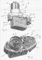
- the heat transfer device 3 may be formed according to a preferred embodiment as a stacked heat exchanger, which consists of stacked and interconnected, for example, soldered, metal discs 4 formed is.
- the filter device 2 consists essentially of a divisible filter housing 5, which is composed of an upper part 6 and a preferably screwed lower part 7 and a non-visible, internal and interchangeable filter element. To replace the filter element, the upper part 6 is unscrewed from the lower part 7 and then withdrawn, thereby exposing the inner filter element.
- the lower part 7 is a one-piece, that is, made in one piece, part of an upper shell 8, which are arranged as a lower shell 9 between the filter device 2 and the heat exchanger device 3.
- the upper shell 8 of the filter device 2 and the lower shell 9 of the heat transfer device 3 are assigned.
- Both the upper shell 8 and the lower shell 9 are formed according to the invention of plastic and at least partially or partially traversed by channels.
- the design of the upper shell 8 on the lower shell 9 made of plastic offer the advantage of a high constructive freedom, a high dimensional accuracy of the two shells 8, 9 and low production costs.
- both shells 8 and 9 are welded or glued together in such a way that the pressures occurring during normal operation of the filter heat exchanger combination 1 can be easily absorbed.
- tie rods 11 which extend for example through aligned openings 15 of the upper shell 8, the lower shell 9 and the base plate 10 therethrough and each outside the openings 15 of the upper and lower shell 8, 9 are supported. Also conceivable are tie rods 11, which are formed either in one piece with the base plate 10 or the upper shell 8 and are accordingly supported either outside the upper shell 8 or outside the base plate 10.
- tie rods 11 are also conceivable, which are supported at one end on an outer side of the upper shell 8 and the other end on an outer side of the base plate 10 and both the upper shell 8, the lower shell 9 and the base plate 10 outside a peripheral edge in the manner of a U- encompass shaped bracket or a screw clamp.
- the base plate 10 of the heat exchanger 3 prevents the operation of the filter-heat exchanger combination 1 dodging or buckling of the lower shell 9, thereby ensuring the tightness between the two Trays 8 and 9 running channels at very high pressures and temperatures.
- the base plate 10 serves as anchoring the tie rods 11, which bias the upper shell 8 against the lower shell 9, wherein the heat exchanger 3 is connected via this base plate 10 with the upper and lower shell 8, 9.
- the tie rods 11 are included for fastening screw means or connected to such.
- both multi-part screwing such as screws with associated nuts, as well as one-piece screwing, which engage for example in an inserted into the base plate 10 internal thread.
- the screw can be formed, for example, as screws with a collar head or as screws with associated collar sleeves, in which a on the filter housing 5 facing surface of the upper shell 8 adjacent support surface is formed as a covenant.
- collar sleeves can be provided that they are inserted on the lower shell 9 side facing away from the upper shell 8, whereas a fastening means 12 in the form of a screw from the upper shell 8 opposite side of the lower shell 9 in the aligned openings 15 of the base plate 10 is inserted and screwed to the collar sleeve.
- tie rods 11 When tightening the tie rods 11 is to ensure that a biasing force of the same is below a creep of the upper shell for the 8 and / or the lower shell 9 related plastic. This is particularly important in terms of tightness the extending between the upper shell 8 and the lower shell 9 channels.
- the tie rods 11 act basically like "rivets" with each outside of the surfaces of the riveted together parts heads.
- the upper shell 8 and the lower shell 9 according to FIGS. 1 to 3 further aligned openings 15a, which are designed to hold not shown fastening means, such as screws, with which the filter-Wärmeübertrager- Kombinaton 1 can be fixed to an internal combustion engine, also not shown.
- the internal combustion engine such as an engine block
- the heat exchanger device 3 protrudes into this opening and thus can be arranged to save space on the internal combustion engine ,
- the fastening means 12 are guided through the openings 15a in the direction of arrow 13 and brought into engagement with an internal thread attached to the internal combustion engine.
- the fasteners 12 At the top or possibly also on the lower shell 8; 9 are the fasteners 12 each zugankerartig from the outside.
- both the upper shell 8 and the lower shell 9 made of plastic also opens up the possibility to spray on these attachment or functional parts 14.
- Such cultivation or functional parts 14 can For example, be holder or coupling elements, which allow, for example, a connection with other parts not shown within an engine compartment.
Landscapes
- Chemical & Material Sciences (AREA)
- Chemical Kinetics & Catalysis (AREA)
- Engineering & Computer Science (AREA)
- Mechanical Engineering (AREA)
- General Engineering & Computer Science (AREA)
- Heat-Exchange Devices With Radiators And Conduit Assemblies (AREA)
- Lubrication Details And Ventilation Of Internal Combustion Engines (AREA)
Applications Claiming Priority (1)
| Application Number | Priority Date | Filing Date | Title |
|---|---|---|---|
| DE200510052163 DE102005052163A1 (de) | 2005-11-02 | 2005-11-02 | Filter-Wärmeübertrager-Kombination für Flüssigkeiten, insbesondere Schmieröl eines Kraftfahrzeug-Verbrennungsmotors |
Publications (2)
| Publication Number | Publication Date |
|---|---|
| EP1782876A1 true EP1782876A1 (fr) | 2007-05-09 |
| EP1782876B1 EP1782876B1 (fr) | 2008-01-02 |
Family
ID=37651070
Family Applications (1)
| Application Number | Title | Priority Date | Filing Date |
|---|---|---|---|
| EP20060119977 Ceased EP1782876B1 (fr) | 2005-11-02 | 2006-09-01 | Ensemble filtre et échangeur de chaleur pour liquides, notamment pour lubrifiant d'un moteur à combustion interne d'un véhicule |
Country Status (2)
| Country | Link |
|---|---|
| EP (1) | EP1782876B1 (fr) |
| DE (2) | DE102005052163A1 (fr) |
Cited By (3)
| Publication number | Priority date | Publication date | Assignee | Title |
|---|---|---|---|---|
| WO2017076766A1 (fr) * | 2015-11-03 | 2017-05-11 | Mahle International Gmbh | Module échangeur thermique |
| CN110821597A (zh) * | 2018-08-13 | 2020-02-21 | 曼·胡默尔有限公司 | 具有热交换器的油过滤器模块 |
| CN111841132A (zh) * | 2020-07-04 | 2020-10-30 | 怀宁县群力汽车配件有限公司 | 一种便于拆装的滤清器外壳 |
Families Citing this family (1)
| Publication number | Priority date | Publication date | Assignee | Title |
|---|---|---|---|---|
| DE102008031684B4 (de) | 2008-07-04 | 2020-02-06 | Mahle International Gmbh | Kühleinrichtung |
Citations (6)
| Publication number | Priority date | Publication date | Assignee | Title |
|---|---|---|---|---|
| GB2163967A (en) * | 1984-08-07 | 1986-03-12 | Nippon Denso Co | Oil filter and cooler |
| EP0551545A1 (fr) * | 1990-07-30 | 1993-07-21 | Calsonic Corporation | Refroidisseur d'huile sans carter |
| US5575329A (en) * | 1994-01-14 | 1996-11-19 | Long Manufacturing Ltd. | Passive by-pass for heat exchangers |
| DE19701066A1 (de) * | 1997-01-15 | 1998-07-16 | Mann & Hummel Filter | Vorrichtung zum Filtrieren von Öl |
| EP1001144A1 (fr) * | 1998-11-13 | 2000-05-17 | Denso Corporation | Dispositif pour le montage d'un refroidisseur d'huile |
| EP1403475A1 (fr) * | 2002-09-26 | 2004-03-31 | Mann+Hummel Gmbh | Unité d' un filtre à liquide et d'un échangeur de chaleur |
Family Cites Families (5)
| Publication number | Priority date | Publication date | Assignee | Title |
|---|---|---|---|---|
| DE19544088A1 (de) * | 1995-11-27 | 1997-05-28 | Knecht Filterwerke Gmbh | Flüssigkeitsfilter mit einem Stapelscheiben-Wärmetauscher |
| FR2757261B1 (fr) * | 1996-12-18 | 1999-02-12 | Valeo Thermique Moteur Sa | Echangeur de chaleur a lames avec filtre integre pour le refroidissement d'huile |
| DE10012461A1 (de) * | 2000-03-15 | 2001-09-20 | Mahle Filtersysteme Gmbh | Flüssigkeitsfilter, insbesondere Ölfilter |
| DE10351112A1 (de) * | 2003-11-03 | 2005-05-25 | Mahle Filtersysteme Gmbh | Wärmetauscher-Einrichtung mit einem Wärmetauscher-Funktionsteil |
| DE102004040892A1 (de) * | 2004-08-24 | 2006-03-02 | Bayerische Motoren Werke Ag | Schmiermittelfilter für eine Brennkraftmaschine |
-
2005
- 2005-11-02 DE DE200510052163 patent/DE102005052163A1/de not_active Withdrawn
-
2006
- 2006-09-01 EP EP20060119977 patent/EP1782876B1/fr not_active Ceased
- 2006-09-01 DE DE200650000263 patent/DE502006000263D1/de active Active
Patent Citations (6)
| Publication number | Priority date | Publication date | Assignee | Title |
|---|---|---|---|---|
| GB2163967A (en) * | 1984-08-07 | 1986-03-12 | Nippon Denso Co | Oil filter and cooler |
| EP0551545A1 (fr) * | 1990-07-30 | 1993-07-21 | Calsonic Corporation | Refroidisseur d'huile sans carter |
| US5575329A (en) * | 1994-01-14 | 1996-11-19 | Long Manufacturing Ltd. | Passive by-pass for heat exchangers |
| DE19701066A1 (de) * | 1997-01-15 | 1998-07-16 | Mann & Hummel Filter | Vorrichtung zum Filtrieren von Öl |
| EP1001144A1 (fr) * | 1998-11-13 | 2000-05-17 | Denso Corporation | Dispositif pour le montage d'un refroidisseur d'huile |
| EP1403475A1 (fr) * | 2002-09-26 | 2004-03-31 | Mann+Hummel Gmbh | Unité d' un filtre à liquide et d'un échangeur de chaleur |
Cited By (7)
| Publication number | Priority date | Publication date | Assignee | Title |
|---|---|---|---|---|
| WO2017076766A1 (fr) * | 2015-11-03 | 2017-05-11 | Mahle International Gmbh | Module échangeur thermique |
| CN108351186A (zh) * | 2015-11-03 | 2018-07-31 | 马勒国际有限公司 | 热交换器模块 |
| JP2018534482A (ja) * | 2015-11-03 | 2018-11-22 | マーレ インターナショナル ゲゼルシャフト ミット ベシュレンクテル ハフツングMAHLE International GmbH | 熱交換器モジュール |
| US10473402B2 (en) | 2015-11-03 | 2019-11-12 | Mahle International Gmbh | Heat exchanger module |
| CN110821597A (zh) * | 2018-08-13 | 2020-02-21 | 曼·胡默尔有限公司 | 具有热交换器的油过滤器模块 |
| CN110821597B (zh) * | 2018-08-13 | 2023-08-04 | 曼·胡默尔有限公司 | 具有热交换器的油过滤器模块 |
| CN111841132A (zh) * | 2020-07-04 | 2020-10-30 | 怀宁县群力汽车配件有限公司 | 一种便于拆装的滤清器外壳 |
Also Published As
| Publication number | Publication date |
|---|---|
| EP1782876B1 (fr) | 2008-01-02 |
| DE502006000263D1 (de) | 2008-02-14 |
| DE102005052163A1 (de) | 2007-05-03 |
Similar Documents
| Publication | Publication Date | Title |
|---|---|---|
| EP2929210B1 (fr) | Amortisseur pour véhicule muni d'une bride de raccordement à un tube de module externe | |
| EP0928405A2 (fr) | Echangeur thermique a plaques, notamment refroidisseur d'huile/refrigerant pour vehicules | |
| EP3163242A1 (fr) | Indirekter ladeluftkühler | |
| DE4309925C2 (de) | Airbag-Einheit | |
| DE69605455T2 (de) | Endkammer für Zusammenbau mit einem Wärmetauscher und Verfahren zu seiner Herstellung | |
| DE4108741C2 (fr) | ||
| DE102005007591A1 (de) | Wärmetauscher | |
| EP2730456B1 (fr) | Entraînement d'un dispositif de réglage de siège pour véhicules automobiles | |
| EP2177725B2 (fr) | Dispositif de filtre | |
| DE19511479C2 (de) | Verbindungsvorrichtung | |
| EP2154465B1 (fr) | Echangeur thermique à plaques | |
| DE10301018B4 (de) | Anordnung zum Verbinden eines rohrförmigen ersten Bauteils mit einem zweiten Bauteil sowie Verfahren zur Herstellung einer solchen Anordnung | |
| EP3037150B1 (fr) | Dispositif de filtre | |
| EP1782876B1 (fr) | Ensemble filtre et échangeur de chaleur pour liquides, notamment pour lubrifiant d'un moteur à combustion interne d'un véhicule | |
| EP2308710B1 (fr) | Réservoir de véhicule utilitaire | |
| EP2698295A2 (fr) | Tube télescopique réglable en longueur, béquille télescopique et procédé de montage | |
| EP3179060A1 (fr) | Capot de culasse | |
| DE102009010296A1 (de) | Verbindungsanordnung eines Anbauteils an einem Karosseriebauteil | |
| EP2331805A1 (fr) | Dispositif de filtration pour moteurs à combustion interne | |
| DE102008049990B4 (de) | Speichervorrichtung und Verfahren zur Herstellung einer Speichervorrichtung | |
| EP1936141A2 (fr) | Soupape de réglage d'un milieu s'écoulant | |
| DE102005029842A1 (de) | Kraftstoffspeicher eines Kraftstoff-Einspritzsystems eines Kraftfahrzeugs | |
| DE102008045749A1 (de) | Aus Kunststoff und Metall bestehender Hybrid-Plattenwärmetauscher | |
| DE19642672A1 (de) | Rohrplatine | |
| EP1712419A1 (fr) | Rail de toit et son procédé de fabrication |
Legal Events
| Date | Code | Title | Description |
|---|---|---|---|
| PUAI | Public reference made under article 153(3) epc to a published international application that has entered the european phase |
Free format text: ORIGINAL CODE: 0009012 |
|
| AK | Designated contracting states |
Kind code of ref document: A1 Designated state(s): AT BE BG CH CY CZ DE DK EE ES FI FR GB GR HU IE IS IT LI LT LU LV MC NL PL PT RO SE SI SK TR |
|
| AX | Request for extension of the european patent |
Extension state: AL BA HR MK YU |
|
| 17P | Request for examination filed |
Effective date: 20070717 |
|
| GRAP | Despatch of communication of intention to grant a patent |
Free format text: ORIGINAL CODE: EPIDOSNIGR1 |
|
| GRAS | Grant fee paid |
Free format text: ORIGINAL CODE: EPIDOSNIGR3 |
|
| GRAA | (expected) grant |
Free format text: ORIGINAL CODE: 0009210 |
|
| AK | Designated contracting states |
Kind code of ref document: B1 Designated state(s): DE FR GB |
|
| REG | Reference to a national code |
Ref country code: GB Ref legal event code: FG4D Free format text: NOT ENGLISH |
|
| AKX | Designation fees paid |
Designated state(s): DE FR GB |
|
| REF | Corresponds to: |
Ref document number: 502006000263 Country of ref document: DE Date of ref document: 20080214 Kind code of ref document: P |
|
| GBT | Gb: translation of ep patent filed (gb section 77(6)(a)/1977) |
Effective date: 20080213 |
|
| ET | Fr: translation filed | ||
| PLBE | No opposition filed within time limit |
Free format text: ORIGINAL CODE: 0009261 |
|
| STAA | Information on the status of an ep patent application or granted ep patent |
Free format text: STATUS: NO OPPOSITION FILED WITHIN TIME LIMIT |
|
| 26N | No opposition filed |
Effective date: 20081003 |
|
| REG | Reference to a national code |
Ref country code: FR Ref legal event code: PLFP Year of fee payment: 10 |
|
| REG | Reference to a national code |
Ref country code: FR Ref legal event code: PLFP Year of fee payment: 11 |
|
| REG | Reference to a national code |
Ref country code: FR Ref legal event code: PLFP Year of fee payment: 12 |
|
| REG | Reference to a national code |
Ref country code: FR Ref legal event code: PLFP Year of fee payment: 13 |
|
| PGFP | Annual fee paid to national office [announced via postgrant information from national office to epo] |
Ref country code: FR Payment date: 20180928 Year of fee payment: 13 |
|
| PGFP | Annual fee paid to national office [announced via postgrant information from national office to epo] |
Ref country code: GB Payment date: 20180928 Year of fee payment: 13 |
|
| PGFP | Annual fee paid to national office [announced via postgrant information from national office to epo] |
Ref country code: DE Payment date: 20181130 Year of fee payment: 13 |
|
| REG | Reference to a national code |
Ref country code: DE Ref legal event code: R119 Ref document number: 502006000263 Country of ref document: DE |
|
| PG25 | Lapsed in a contracting state [announced via postgrant information from national office to epo] |
Ref country code: DE Free format text: LAPSE BECAUSE OF NON-PAYMENT OF DUE FEES Effective date: 20200401 |
|
| GBPC | Gb: european patent ceased through non-payment of renewal fee |
Effective date: 20190901 |
|
| PG25 | Lapsed in a contracting state [announced via postgrant information from national office to epo] |
Ref country code: FR Free format text: LAPSE BECAUSE OF NON-PAYMENT OF DUE FEES Effective date: 20190930 Ref country code: GB Free format text: LAPSE BECAUSE OF NON-PAYMENT OF DUE FEES Effective date: 20190901 |