EP1782887A1 - Düse eines Ringes und Verfahren zu deren Verwendung - Google Patents
Düse eines Ringes und Verfahren zu deren Verwendung Download PDFInfo
- Publication number
- EP1782887A1 EP1782887A1 EP06023260A EP06023260A EP1782887A1 EP 1782887 A1 EP1782887 A1 EP 1782887A1 EP 06023260 A EP06023260 A EP 06023260A EP 06023260 A EP06023260 A EP 06023260A EP 1782887 A1 EP1782887 A1 EP 1782887A1
- Authority
- EP
- European Patent Office
- Prior art keywords
- fluid
- ring
- cylindrical member
- nozzle plug
- energy mill
- Prior art date
- Legal status (The legal status is an assumption and is not a legal conclusion. Google has not performed a legal analysis and makes no representation as to the accuracy of the status listed.)
- Withdrawn
Links
- 238000000034 method Methods 0.000 title claims description 7
- 239000012530 fluid Substances 0.000 claims abstract description 194
- 238000000227 grinding Methods 0.000 claims abstract description 97
- 230000006835 compression Effects 0.000 claims abstract description 50
- 238000007906 compression Methods 0.000 claims abstract description 50
- 239000013618 particulate matter Substances 0.000 claims abstract description 41
- 238000011144 upstream manufacturing Methods 0.000 claims description 13
- 230000001133 acceleration Effects 0.000 claims description 11
- IJGRMHOSHXDMSA-UHFFFAOYSA-N Atomic nitrogen Chemical compound N#N IJGRMHOSHXDMSA-UHFFFAOYSA-N 0.000 claims description 6
- GWEVSGVZZGPLCZ-UHFFFAOYSA-N Titan oxide Chemical compound O=[Ti]=O GWEVSGVZZGPLCZ-UHFFFAOYSA-N 0.000 claims description 6
- 239000000049 pigment Substances 0.000 claims description 4
- 239000003905 agrochemical Substances 0.000 claims description 3
- 239000006229 carbon black Substances 0.000 claims description 3
- 239000000919 ceramic Substances 0.000 claims description 3
- 239000002537 cosmetic Substances 0.000 claims description 3
- 239000003814 drug Substances 0.000 claims description 3
- 229910052500 inorganic mineral Inorganic materials 0.000 claims description 3
- 239000002184 metal Substances 0.000 claims description 3
- 229910052751 metal Inorganic materials 0.000 claims description 3
- 150000002739 metals Chemical class 0.000 claims description 3
- 239000011707 mineral Substances 0.000 claims description 3
- 229910052757 nitrogen Inorganic materials 0.000 claims description 3
- 239000010970 precious metal Substances 0.000 claims description 3
- 239000003380 propellant Substances 0.000 claims description 3
- 239000011347 resin Substances 0.000 claims description 3
- 229920005989 resin Polymers 0.000 claims description 3
- 239000004408 titanium dioxide Substances 0.000 claims description 3
- 239000002245 particle Substances 0.000 abstract description 30
- 239000007789 gas Substances 0.000 description 17
- 239000000463 material Substances 0.000 description 4
- 238000010951 particle size reduction Methods 0.000 description 4
- 239000002131 composite material Substances 0.000 description 2
- -1 for example Substances 0.000 description 2
- 238000005549 size reduction Methods 0.000 description 2
- 238000005299 abrasion Methods 0.000 description 1
- 238000005054 agglomeration Methods 0.000 description 1
- 230000002776 aggregation Effects 0.000 description 1
- 229910010293 ceramic material Inorganic materials 0.000 description 1
- 239000011248 coating agent Substances 0.000 description 1
- 238000000576 coating method Methods 0.000 description 1
- 238000005520 cutting process Methods 0.000 description 1
- 230000007423 decrease Effects 0.000 description 1
- 230000003247 decreasing effect Effects 0.000 description 1
- QDOXWKRWXJOMAK-UHFFFAOYSA-N dichromium trioxide Chemical compound O=[Cr]O[Cr]=O QDOXWKRWXJOMAK-UHFFFAOYSA-N 0.000 description 1
- 230000000694 effects Effects 0.000 description 1
- 238000005265 energy consumption Methods 0.000 description 1
- 239000010419 fine particle Substances 0.000 description 1
- 238000003780 insertion Methods 0.000 description 1
- 230000037431 insertion Effects 0.000 description 1
- JEIPFZHSYJVQDO-UHFFFAOYSA-N iron(III) oxide Inorganic materials O=[Fe]O[Fe]=O JEIPFZHSYJVQDO-UHFFFAOYSA-N 0.000 description 1
- 238000004519 manufacturing process Methods 0.000 description 1
- 239000007769 metal material Substances 0.000 description 1
- TWNQGVIAIRXVLR-UHFFFAOYSA-N oxo(oxoalumanyloxy)alumane Chemical compound O=[Al]O[Al]=O TWNQGVIAIRXVLR-UHFFFAOYSA-N 0.000 description 1
- 238000007493 shaping process Methods 0.000 description 1
- 239000007787 solid Substances 0.000 description 1
- 229910001220 stainless steel Inorganic materials 0.000 description 1
- 239000010935 stainless steel Substances 0.000 description 1
- 239000011882 ultra-fine particle Substances 0.000 description 1
Images


Classifications
-
- B—PERFORMING OPERATIONS; TRANSPORTING
- B02—CRUSHING, PULVERISING, OR DISINTEGRATING; PREPARATORY TREATMENT OF GRAIN FOR MILLING
- B02C—CRUSHING, PULVERISING, OR DISINTEGRATING IN GENERAL; MILLING GRAIN
- B02C19/00—Other disintegrating devices or methods
- B02C19/06—Jet mills
- B02C19/061—Jet mills of the cylindrical type
Definitions
- the embodiments of the present invention relate to a ring jet, particularly for use in fluid energy mills.
- the embodiments relate to a spiked nozzle containing a nozzle plug forming a fluid compression orifice in form of a partial annulus, to accelerate a grinding fluid used in reducing the particle size of particulate matter.
- Fluid energy mills are used to reduce the particle size of a variety of materials such as pigments, agricultural chemicals, carbon black, ceramics, minerals and metals, pharmaceuticals, cosmetics, precious metals, propellants, resins, toner and titanium dioxide.
- the particle size reduction typically occurs as a result of particle-to-particle collisions because generally, a fluid energy mill contains no moving parts.
- the fluid energy mill typically comprises a hollow interior that acts as a grinding chamber where the particle collisions occur.
- a vortex is formed via the introduction of a compressed gas or grinding fluid through fluid nozzles positioned in an annular configuration around the periphery of the grinding chamber.
- the compressed gas e.g., air, steam, nitrogen, etc.
- the gas circles within the grinding chamber at a decreased radii until released from the grinding chamber through a gas outlet.
- the particles to be ground are deposited within the grinding chamber and swept up into the high-speed vortex, thereby resulting in high speed particle-to-particle collisions as well as collisions with the interior portion of the grinding chamber walls.
- fluid energy mills are capable of producing fine (less than 10 microns) and ultra fine (less than 5 microns) particles.
- Typical nozzles that have been used include DeLaval nozzles (converging-diverging nozzles) through which the grinding fluid (also known as compression gas) is injected into the grinding chamber.
- the grinding fluid also known as compression gas
- the shear zone the high-velocity grinding fluid
- such nozzles are disadvantageous because the pattern of the gas exiting the nozzle results in a substantial core of the gas-stream flow that is unavailable for grinding as the particles cannot penetrate the core of the fluid flow. Therefore, a greater amount of energy is necessary and a greater volume of compression gas is required to grind the particulate matter to the desired particle size.
- the present invention proposes placing ring jets in an annular configuration around the fluid energy mill.
- These ring jets have a spiked nozzle with a 'C' shaped compression orifice and opening.
- the spiked nozzle is shaped such that its surface is flush with the inside wall of the fluid energy mill. Grinding fluid emanating from the ring jets attrites the larger particles that are found closer to the wall of the fluid energy mill. Once the larger particles are ground to finer particles of desired size, such smaller particles leave the chamber through an outlet.
- This invention relates to a ring jet, comprising:
- This invention also relates to a nozzle plug, comprising:
- This invention further relates to a fluid energy mill comprising at least one ring jet at an angle, in a ring configuration, along the outer wall of said fluid energy mill, wherein said ring jet comprises:
- This invention also relates to a method of reducing the size of particulate matter comprising:
- grinding of particulate matter is meant a possible “size reduction” of particulate matter.
- size reduction of particulate matter.
- the term “grinding” and the term “size reduction” may be used interchangeably in this application. Both the terms are equivalent in their meaning.
- ring jet and the term “spiked nozzle” may be used interchangeably in this application. Both the terms are equivalent in their meaning.
- the present invention relates to spiked nozzles and their use in grinding of particulates in a fluid energy mill.
- particulate matter for example pigment particulates
- a grinding fluid is entrained with a grinding fluid and injected into the chamber of a fluid energy mill by a large feed jet and a feed tube.
- the particulates and the grinding fluid then enter a circular ring situated around the main body of the fluid energy mill. This ring is surrounded by small supersonic jets with the spiked nozzles, referred to as ring jets.
- This invention relates to such ring jets.
- large particles of the particulate matter in the grinding stream moving in circular direction along the circular wall of the fluid energy mill, are classified out of the main flow of the grinding stream and end up closer, and against the inner surface of the outer wall of the fluid energy mill, where these particles are eventually caught by a ring jet.
- the small, but high-velocity gas streams (grinding fluid) emanating from the ring jets entrain the large particles and cause their attrition (among other things) through high-speed shear, particle-to-particle collisions, and/or particle-to-wall collisions. Eventually, the attrited particles join the main grinding stream flow out of the body of the fluid energy mill.
- Embodiments of the present invention relate to such spiked nozzles.
- Such spiked nozzles comprise a nozzle plug to form a fluid acceleration region that can increase the velocity of a grinding fluid to allow for particle-size reduction.
- the nozzle plug is shaped such that it allows for the exit point of the ring jet to be placed more closely to the inner surface of the outer wall of the fluid energy mill. Therefore circulating particulate matter can encounter the ring jet closer to the nozzle exit where the shear force from the grinding stream is the highest.
- This is accomplished by truncating the conical nozzle plug and shaping it such that it plugs a portion of the compression orifice of the ring jet, to form a C-shaped, partially-annular, compression orifice (for comparison purposes, if the nozzle plug were symmetrical, the compression orifice would be an 'O' shaped annular orifice).
- the nozzle plug is truncated at an angle that will allow the ring jet exit point to be essentially flush with the inner surface of the outer wall.
- the truncated nozzle plug is cut in such a way as to create the C-shaped cone of high-energy grinding fluid (steam, for example) with over twice the surface area of a standard DeLaval nozzle. Consequently, not only is the nozzle sized for a smaller gas flow but is also made more efficient at converting the shear force to grinding energy due to the extended surface area and the 'C' shape.
- the ring jet embodiments provide a fluid velocity (or fluid acceleration) that is greater than that found with other types of nozzles (e.g., DeLaval nozzles).
- the embodiments of the present invention result in a high velocity fluid flow (e.g., supersonic velocities) having a reduced core portion of the fluid flow, thereby subjecting the particulate matter to a shear zone.
- the spiked nozzle is capable of providing an increased fluid velocity, a greater fluid surface area having the higher velocity, and a reduction in the energy consumption of a fluid energy mill.
- the embodiments of the present invention may be utilized in the particle-size reduction of a wide variety of particulate matter.
- suitable types of particulate matter include pigments, agricultural chemicals, carbon black, ceramics, minerals and metals, pharmaceuticals, cosmetics, precious metals, propellants, resins, toner and titanium dioxide. Grinding combinations of a variety of particulate matter may also be performed.
- the particulate matter is entrained in a grinding fluid feed stream, which may be compressed air or other gas or a combination of gases.
- the operation of a fluid energy mill includes the use of a first grinding fluid (101) and a second grinding fluid (600).
- the first grinding fluid (101) or the second grinding fluid (600) may comprise a single fluid or a combination of fluids thereby forming a composite fluid stream.
- the combinations of fluids and the proportions of each fluid therein may be varied to meet the necessary parameters for the particular grinding application.
- Non-limiting examples of grinding fluids include air, nitrogen, steam and combinations thereof, wherein steam is preferred.
- Composite fluid streams may comprise steam and a second gas or other combination of gases.
- the first or the second grinding fluid is delivered at a particular temperature and pressure.
- a temperature and pressure are known to those skilled in the art.
- steam is often heated to a temperature ranging from about 220°C to about 340°C, preferably ranging from about 260°C to about 305°C prior to delivery into the spiked nozzle.
- it is supplied at a pressure of about 375 psi (2.580 MPa) to about 500 psi (3.450 MPa), more preferably ranging from about 390 psi (2.688 MPa) to about 440 psi (3.032 MPa).
- an embodiment of a spiked nozzle operated at the above-described parameters would result in the grinding fluid having a velocity (when measured at the point of discharge from the spiked nozzle) of up to about Mach 6.8 (A speed of Mach 1 corresponds to the speed of sound, which is about 340 m/s. A speed of Mach 6.8 is 6.8 times the speed of sound, i.e., about 2312 m/s).
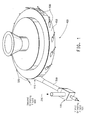
- particulate matter (200) is supplied to the fluid energy mill (400) through a feed jet (100), wherein the first grinding fluid (101) entrains the particulate matter (200) fed to the feed jet (100).
- the particulate matter (200) is then carried through a feed tube (300) into a fluid energy mill (400) through an inlet (440) to the fluid energy mill (400).
- the fluid energy mill (400) has spiked-nozzle shaped ring jets (500) situated in a circular orientation, or a ring (450), about the fluid energy mill.
- the fluid energy mill (400) has at least one ring jet (500). In another embodiment, the fluid energy mill (400) can have as many as 50 ring jets (500) placed about the fluid energy mill (400) in the circular orientation.
- a ring jet may be placed equidistant from its two neighboring ring jets. In another embodiment, a ring jet may not be placed equidistant from its two neighboring ring jets. In another embodiment, some ring jets may be placed equidistant from their neighbors and other ring jets may not be placed equidistant from their neighbors.
- the range of the number of ring jets is selected from the group consisting of 1 to 5, 1 to 10, 1 to 15, 1 to 20, 1 to 25, 1 to 30, 1 to 35, 1 to 40, 1 to 45, 1 to 50, 1 to 3, 4 to 6, 7 to 9, 10 to 12, 13 to 15, 16 to 18, 19 to 21, 22 to 24, 25 to 27, 28 to 30, 31 to 33, 34 to 36, 37 to 39, 40 to 42, 43 to 45, 46 to 48, and 49 to 50.
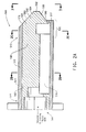
- FIG 2A the cross-sectional side view of the ring jet is shown.
- a ring jet in the configuration of a spiked nozzle (500) comprising:
- the components (e.g., the cylindrical member, nozzle plug, etc.) of the present invention may be constructed of any material capable of withstanding the temperatures, forces, and pressures generated and encountered during normal operation of a fluid energy mill (400).
- the cylindrical member (510) may be machined or constructed of materials such as, for example, solid bar stock or heavy walled pipe (e.g., Schedule 40, 80 or 160 pipe, which are known to those skilled in the art).
- the nozzle plug (530) is typically constructed of any metallic material or cast from ceramic materials.
- the nozzle plug (530) is constructed of a rust resistant material such as, for example, stainless steel.
- the cylindrical member (510) acts as a conduit to introduce the grinding fluid (600) into the grinding chamber of the fluid energy mill (400) such that the grinding fluid (600) flows past the nozzle plug (530).
- the cylindrical member (510) may be of any size known in the art to be suitable for use with fluid energy mills.
- the surface area of the grinding fluid jet area available for grinding
- a better shear zone a greater grinding surface area
- the cylindrical member (510) comprises an outer face (511) and an inner face (512) as well as a first end (514) and a second end (515) thereby defining a hollow interior (516) through which the second grinding fluid (600) travels.
- the first end (514) is upstream of the second end (515) such that the second grinding fluid (600) flow is generally away from the first end (514) and towards the second end (515).
- the second end (515) of the cylindrical member (510) contains the fluid acceleration region (520) of the spiked nozzle or the ring jet (500), wherein the second grinding fluid (600) is subjected to a fluid compression orifice (580), thereby accelerating it to a high velocity as it exits from the spiked nozzle or the ring jet (500).
- the fluid compression orifice (580) is formed by the insertion of the nozzle plug (530) into the second end (515) of the cylindrical member (510) and in conjunction with the cowl lip (517) of the cylindrical member (510).
- the fluid compression orifice is shaped in a 'C' when viewed from the second end (515) into the ring jet (See FIG. 3).
- FIG. 2B shows the cross section of the spiked nozzle closer to the upstream end (541) of the nozzle (see also FIG. 2A).
- This view represents the channel (516) created in between the cylindrical member (510) and the partially cylindrical portion (540) through which the second grinding fluid (600) travels before encountering the fluid acceleration region (520).
- the spiked nozzle or the ring jet (500) is shaped such that it allows the exit of the ring jet to be placed more closely to the inner surface of the outer wall of the fluid energy mill (400).
- circulating particulate matter (200), now entrained in the fluid energy mill (400), can encounter the ring jets closer to the nozzle exit that is the truncated spike (552) where the shear force from the second grinding fluid (600) is the highest. This is accomplished by truncating the ramped portion of the conical nozzle plug (550) and plugging one end of its rim (570), and cutting it off at an angle that will allow the conical nozzle plug (530) to be essentially flush with the inner surface of the outer wall of the fluid energy mill (400).
- the truncated ramped portion (550) of the conical nozzle plug (530) is cut in such a way as to create a 'C' shaped cone (575) of high-energy second grinding fluid (steam) (600) with over twice the surface area of a standard DeLaval nozzle. Consequently, not only is the nozzle sized for a smaller gas flow, for example steam, but also made more efficient at converting the shear to grinding energy due to the extended surface area and the 'C' shape.
- the nozzle plug (530) comprises a means for securing the nozzle plug to the cylindrical member (e.g. a second cylindrical portion (531) as set forth below), a partially-cylindrical portion (540) and a ramped portion (550) ending in the nozzle exit that is the truncated spike (552).
- a means for securing the nozzle plug to the cylindrical member include, but are not limited to, a second cylindrical portion (531) as further described herein, or fins, bars or arms (welded or otherwise connected to or formed in the partially-cylindrical portion (540)) wherein such fins, arms or bars extend from the partially-cylindrical portion (540) to the inner face (512) of the cylindrical member (510).
- the methods utilized to secure the nozzle plug within the cylindrical member should provide for the necessary stability and support such that the nozzle plug (530) remains properly centered and plugged so that during the normal operation of a fluid energy mill (400), the fluid compression orifice (580) remains consistent in its 'C' shape over its area in terms of grinding fluid flow.
- the second grinding fluid (600) exits the ring jet (500) at an angle in the range of from about 10° to the tangent at the inner surface of the outer wall of the fluid energy mill (400) to about 50° to the tangent at the inner surface of the wall of the fluid energy mill (400).
- This angle can be changed as desired by changing the ring jets (500) and the truncation of the ramped portion (550) of the nozzle plug (530) such that the truncated spike at the ring jet exit (552) of the nozzle plug (530) is flush with the inner surface of the wall of the fluid energy mill (400), creating a 'C' shape for the compression orifice (580) from which the second grinding fluid is thrust out into the fluid energy mill (400) chamber at supersonic speed, if desired.
- a pressure drop may result as a consequence of the means for securing the nozzle plug to the cylindrical member, although the pressure drop is preferably not greater than 5%.
- the partially-cylindrical portion (540) is connected with the cylindrical portion (510) at its upstream end (541).
- the partially-cylindrical portion (540) and ramped portion (550) may be originally formed as a unitary structure, or alternatively, may be individual pieces that are welded together to form a single piece.
- the partially-cylindrical portion (540) is not limited to any particular diameter or length so long as the requisite level of stability and structural integrity is conferred to the entirety of the nozzle plug (530), and the compression orifice (580) assumes a 'C' shape in conjunction with the cowl lip (517).
- the ramped portion (550) of the nozzle plug (530) is machined off flat to match the inside flow line of the liner of the fluid energy mill.
- the surface of the nozzle plug (530) is hyperbolic comprising a proximal end (553) and a distal end (554), wherein the ramped portion decreases in diameter in the downstream direction until it ends in a truncated spike (552).
- the ramped portion (550) in conjunction with the cowl lip (517) forms a 'C' shaped compression orifice (580) and the exit for the grinding fluid (600).
- the curve of the ramped portion (550) is such that the initial entrance is on a tangent about 45 degrees (the angle at which the second grinding fluid (600) exits the fluid compression orifice (580) from the central nozzle axis and then tapers to various lengths, although the tangent angle may vary such that for example it may measure 35 degrees.
- the truncated spike 552 creates turbulence in the fluid flow, thereby generating a lift to the flow and directing it towards the outside of the nozzle flow.
- the length of the ramped portion can be 2.5 times the diameter of the ramped portion as measured at its widest point.
- the ramp is machined off to match the inside curvature of the liner, which is a function of the projection of the entire nozzle.
- the fluid compression orifice (580) serves to accelerate the second grinding fluid (600) as a constant volume of second grinding fluid (600) entering the ring jet must exit through the restrictive fluid compression orifice (580).
- the partially-annular area of the fluid compression orifice (580) is up to about 60% of the area of a throat cross section of a similar DeLaval nozzle.
- the fluid compression orifice (580) is formed by the proximal end (553) of the hyperbolic section of the nozzle plug (530) and a cowl lip (517) formed at the second end (515) of the cylindrical member (510) (See FIG. 2A).
- the nozzle plug (530) is shaped in such a way that it plugs a portion of the compression orifice (580) to provide a 'C' shaped compression orifice. If the ramped portion (550) of the nozzle plug (530) were axisymmetric, such a plug would have formed an annular-shaped compression orifice.
- the spike of the nozzle plug (552) is truncated at an angle such that when the entire ring jet assembly (500) is attached to the inner surface of the outer wall of the fluid energy mill (400) at a desired angle to a direction tangential to the inside wall of the fluid energy mill (400) and the truncated spike (552) of the ramped portion (550) of the nozzle plug (530) is flush with the inner surface of the outer wall of the fluid energy mill (400).
- a ring jet exit appears as a 'C' shape in a ring configuration.
- the fluid compression orifice (580) should be sized with the equivalent ratio of a DeLaval jet.
- the fluid compression orifice width is about 10 times longer than the gap.
- a typical DeLaval nozzle (having a throat diameter of 5.08 cm (2 inches)) has a fluid compression orifice area of about 6.45 cm 2 (1 sq. in).
- an embodiment of the present invention having the same equivalent grinding (rate/product) as the DeLaval nozzle generally has a fluid compression orifice total area that is about 60% of the measured area found in the DeLaval nozzle and flows about 40% less compression fluid.
- the area of the fluid compression orifice may vary according to the desired flow rate of the grinding fluid and the type of product undergoing particle size reduction.
- the embodiments of the present invention may further be coated with an abrasion resistant coating such as aluminum oxide, or chrome oxide to prevent clogging or agglomeration at the spiked nozzle tip (552) when sticky particulate matter is being ground.
- an abrasion resistant coating such as aluminum oxide, or chrome oxide to prevent clogging or agglomeration at the spiked nozzle tip (552) when sticky particulate matter is being ground.
- the ring jet (500) is operated by the introduction of second grinding fluid (600) into the first end (514) of the cylindrical member (510) at velocities that vary greatly depending upon the type of second grinding fluid (600), the pressure at which it is used during normal operation, and the amount of grinding energy required to reach a particular particle size.
- the second grinding fluid (600) travels along the major nozzle axis until it encounters the fluid compression orifice (580). As the second grinding fluid (600) passes through the fluid compression orifice (580) it undergoes severe acceleration, increasing its velocity from substantially its initial introduction velocity to supersonic velocities.
- the second grinding fluid (600) moves through the ring jet (500), its velocity increases until its maximum velocity is reached as the compressed fluid exits the spiked nozzle (500).
- the second grinding fluid (600) undergoes expansion as it exits the fluid compression region (580) as a result of the truncated spike (552).
- the second grinding fluid (600) expands in a 'C' shape and in an inward direction towards the major nozzle axis.
- the turbulent flow assists in causing the particle-to-particle collisions.
- larger particles are classified toward the outer wall of the fluid energy mill (400) such that they come in contact with the second grinding fluid (600) emanating at supersonic velocity from a ring jet (500) at very high shear.
- the larger particles are gradually attrited to a smaller desired size.
- the smaller particles then subsequently are mixed into the mainstream of the particulates exiting the fluid energy mill chamber.
- the particulate matter is entrained at the point of highest velocity, which is at the discharge area of the fluid compression orifice (580) (i.e., the tip of the spiked nozzle (552) (also known as the plane at the exit of the nozzle).
- the reduction in particle size generally occurs in the shear zone, which exists at the intersection or boundary between the particulate matter feed stream and the high velocity fluid exiting the ring jet (500).
- the increased size of the shear zone surface area translates into the need to utilize a smaller volume of the second grinding fluid (600) to achieve the same result seen with standard jets.
- the embodiments of the present invention allow a fluid energy mill to perform more efficiently such that less energy is consumed in the production of the same volume of fine or ultra-fine particles as those nozzles currently used.
- the overall effect of the embodiments of the present invention is an increase in grinding efficiency.
Landscapes
- Engineering & Computer Science (AREA)
- Food Science & Technology (AREA)
- Disintegrating Or Milling (AREA)
Applications Claiming Priority (1)
| Application Number | Priority Date | Filing Date | Title |
|---|---|---|---|
| US11/269,777 US7621473B2 (en) | 2005-11-08 | 2005-11-08 | Ring jet nozzle and process of using the same |
Publications (1)
| Publication Number | Publication Date |
|---|---|
| EP1782887A1 true EP1782887A1 (de) | 2007-05-09 |
Family
ID=37758833
Family Applications (1)
| Application Number | Title | Priority Date | Filing Date |
|---|---|---|---|
| EP06023260A Withdrawn EP1782887A1 (de) | 2005-11-08 | 2006-11-08 | Düse eines Ringes und Verfahren zu deren Verwendung |
Country Status (3)
| Country | Link |
|---|---|
| US (2) | US7621473B2 (de) |
| EP (1) | EP1782887A1 (de) |
| AU (1) | AU2006235889A1 (de) |
Cited By (1)
| Publication number | Priority date | Publication date | Assignee | Title |
|---|---|---|---|---|
| CN106334614A (zh) * | 2015-07-08 | 2017-01-18 | 中外炉工业株式会社 | 粉碎装置和包括上述粉碎装置的处理装置 |
Families Citing this family (11)
| Publication number | Priority date | Publication date | Assignee | Title |
|---|---|---|---|---|
| US7520451B2 (en) * | 2004-12-29 | 2009-04-21 | E. I. Du Pont De Nemours And Company | Spiked axisymmetric nozzle and process of using the same |
| US8083162B2 (en) * | 2007-08-23 | 2011-12-27 | Liquajet L.L.C. | Method for micro-sizing organic, inorganic and engineered compounds |
| US9050604B1 (en) | 2014-06-06 | 2015-06-09 | LLT International (Ireland) Ltd. | Reactor configured to facilitate chemical reactions and/or comminution of solid feed materials |
| US9724703B2 (en) | 2014-06-06 | 2017-08-08 | LLT International (Ireland) Ltd. | Systems and methods for processing solid materials using shockwaves produced in a supersonic gaseous vortex |
| US9452434B1 (en) | 2015-04-17 | 2016-09-27 | LLT International (Ireland) Ltd. | Providing wear resistance in a reactor configured to facilitate chemical reactions and/or comminution of solid feed materials using shockwaves created in a supersonic gaseous vortex |
| US10427129B2 (en) | 2015-04-17 | 2019-10-01 | LLT International (Ireland) Ltd. | Systems and methods for facilitating reactions in gases using shockwaves produced in a supersonic gaseous vortex |
| US10434488B2 (en) | 2015-08-11 | 2019-10-08 | LLT International (Ireland) Ltd. | Systems and methods for facilitating dissociation of methane utilizing a reactor designed to generate shockwaves in a supersonic gaseous vortex |
| JP6756111B2 (ja) * | 2016-01-21 | 2020-09-16 | 堺化学工業株式会社 | 粉体粉砕方法及び粉体粉砕装置 |
| US10550731B2 (en) | 2017-01-13 | 2020-02-04 | LLT International (Ireland) Ltd. | Systems and methods for generating steam by creating shockwaves in a supersonic gaseous vortex |
| US11203725B2 (en) | 2017-04-06 | 2021-12-21 | LLT International (Ireland) Ltd. | Systems and methods for gasification of carbonaceous materials |
| CN119425916A (zh) * | 2024-10-10 | 2025-02-14 | 广药王老吉(毕节)产业有限公司 | 一种超微粉碎装置、中药制剂分离提纯用原料粉碎机 |
Citations (3)
| Publication number | Priority date | Publication date | Assignee | Title |
|---|---|---|---|---|
| US20040016835A1 (en) * | 2002-07-23 | 2004-01-29 | Xerox Corporation | Particle entraining eductor-spike nozzle device for a fluidized bed jet mill |
| JP2005118725A (ja) * | 2003-10-17 | 2005-05-12 | Ace Giken:Kk | 粉砕ノズル、供給ノズル及びそれを備えたジェットミル、並びにそれを用いた砕料の粉砕方法 |
| WO2006072073A2 (en) * | 2004-12-29 | 2006-07-06 | E.I. Du Pont De Nemours And Company | Spiked axisymmetric nozzle and process of using the same |
Family Cites Families (8)
| Publication number | Priority date | Publication date | Assignee | Title |
|---|---|---|---|---|
| US3178121A (en) * | 1962-04-24 | 1965-04-13 | Du Pont | Process for comminuting grit in pigments and supersonic fluid energy mill therefor |
| US4416421A (en) * | 1980-10-09 | 1983-11-22 | Browning Engineering Corporation | Highly concentrated supersonic liquified material flame spray method and apparatus |
| FR2509017B1 (fr) * | 1981-07-03 | 1986-04-04 | Creusot Loire | Procede et dispositif de pulverisation d'une matiere combustible solide |
| US4567960A (en) * | 1982-08-23 | 1986-02-04 | The Boeing Company | Fixed geometry controlled entrainment ventilated convergent nozzle and method |
| DE3721512C1 (de) * | 1987-06-30 | 1989-03-30 | Diehl Gmbh & Co | Flugkoerper mit ueberkalibrigem Leitwerk |
| US4860959A (en) | 1988-06-23 | 1989-08-29 | Semi-Bulk Systems, Inc. | Apparatus for subjecting particles dispersed in a fluid to a shearing action |
| US5683039A (en) * | 1996-03-28 | 1997-11-04 | Xerox Corporation | Laval nozzle with central feed tube and particle comminution processes thereof |
| US7422167B2 (en) * | 2002-04-11 | 2008-09-09 | Sturtevant, Inc. | Fluid-energy mill |
-
2005
- 2005-11-08 US US11/269,777 patent/US7621473B2/en not_active Expired - Fee Related
-
2006
- 2006-11-06 AU AU2006235889A patent/AU2006235889A1/en not_active Abandoned
- 2006-11-08 EP EP06023260A patent/EP1782887A1/de not_active Withdrawn
-
2009
- 2009-10-13 US US12/577,792 patent/US20100025506A1/en not_active Abandoned
Patent Citations (3)
| Publication number | Priority date | Publication date | Assignee | Title |
|---|---|---|---|---|
| US20040016835A1 (en) * | 2002-07-23 | 2004-01-29 | Xerox Corporation | Particle entraining eductor-spike nozzle device for a fluidized bed jet mill |
| JP2005118725A (ja) * | 2003-10-17 | 2005-05-12 | Ace Giken:Kk | 粉砕ノズル、供給ノズル及びそれを備えたジェットミル、並びにそれを用いた砕料の粉砕方法 |
| WO2006072073A2 (en) * | 2004-12-29 | 2006-07-06 | E.I. Du Pont De Nemours And Company | Spiked axisymmetric nozzle and process of using the same |
Cited By (2)
| Publication number | Priority date | Publication date | Assignee | Title |
|---|---|---|---|---|
| CN106334614A (zh) * | 2015-07-08 | 2017-01-18 | 中外炉工业株式会社 | 粉碎装置和包括上述粉碎装置的处理装置 |
| JP2017018871A (ja) * | 2015-07-08 | 2017-01-26 | 中外炉工業株式会社 | 解砕装置及び前記解砕装置を備える処理装置 |
Also Published As
| Publication number | Publication date |
|---|---|
| US7621473B2 (en) | 2009-11-24 |
| US20100025506A1 (en) | 2010-02-04 |
| AU2006235889A1 (en) | 2007-05-24 |
| US20070102546A1 (en) | 2007-05-10 |
Similar Documents
| Publication | Publication Date | Title |
|---|---|---|
| US20100025506A1 (en) | Ring jet nozzle and process of using the same | |
| CN102272524B (zh) | 双组分喷嘴、集束喷嘴以及用于使流体雾化的方法 | |
| US4248387A (en) | Method and apparatus for comminuting material in a re-entrant circulating stream mill | |
| US6951312B2 (en) | Particle entraining eductor-spike nozzle device for a fluidized bed jet mill | |
| CA1231235A (en) | Method and apparatus for forming a high velocity liquid abrasive jet | |
| US6942170B2 (en) | Plural odd number bell-like openings nozzle device for a fluidized bed jet mill | |
| US7485027B2 (en) | Abrasive entrainment | |
| JP3335312B2 (ja) | ジェットミル | |
| TW201446329A (zh) | 用噴射磨製造形態優化的細顆粒的方法、用於該方法的噴射磨和所製造的顆粒 | |
| US7520451B2 (en) | Spiked axisymmetric nozzle and process of using the same | |
| US7959095B2 (en) | Center-feed nozzle in a contained cylindrical feed-inlet tube for improved fluid-energy mill grinding efficiency | |
| US5683039A (en) | Laval nozzle with central feed tube and particle comminution processes thereof | |
| JPH01215354A (ja) | 粉砕およびコーティング装置 | |
| JPS6018454B2 (ja) | 対向式ジエツトミル | |
| JPH02152559A (ja) | 粉砕およびコーティング装置 | |
| JP2000140675A (ja) | 粉砕装置 | |
| JP2017176913A (ja) | 粉砕装置 | |
| JPH0667492B2 (ja) | ジエツト気流式粉砕機 | |
| JP2005118725A (ja) | 粉砕ノズル、供給ノズル及びそれを備えたジェットミル、並びにそれを用いた砕料の粉砕方法 | |
| JP4575017B2 (ja) | 固気混合エジェクタおよびジェットミル | |
| JPS6350404A (ja) | 金属粉末製造用噴霧ノズル | |
| EP1669137B1 (de) | Materialaufbrechvorrichtung | |
| US20080057839A1 (en) | Abrasivejet Cutting Head With Novel Entrainment Structure and Method | |
| JP2003047880A (ja) | 粉砕ノズル、補助粉砕ノズル、及びそれらを備えたジェットミル | |
| US20130034808A1 (en) | Pulverizer, pulverization method, toner production method, and toner |
Legal Events
| Date | Code | Title | Description |
|---|---|---|---|
| PUAI | Public reference made under article 153(3) epc to a published international application that has entered the european phase |
Free format text: ORIGINAL CODE: 0009012 |
|
| AK | Designated contracting states |
Kind code of ref document: A1 Designated state(s): AT BE BG CH CY CZ DE DK EE ES FI FR GB GR HU IE IS IT LI LT LU LV MC NL PL PT RO SE SI SK TR |
|
| AX | Request for extension of the european patent |
Extension state: AL BA HR MK YU |
|
| 17P | Request for examination filed |
Effective date: 20070507 |
|
| 17Q | First examination report despatched |
Effective date: 20070618 |
|
| AKX | Designation fees paid |
Designated state(s): DE GB |
|
| GRAP | Despatch of communication of intention to grant a patent |
Free format text: ORIGINAL CODE: EPIDOSNIGR1 |
|
| STAA | Information on the status of an ep patent application or granted ep patent |
Free format text: STATUS: THE APPLICATION IS DEEMED TO BE WITHDRAWN |
|
| 18D | Application deemed to be withdrawn |
Effective date: 20100511 |