EP1782935A1 - Moule métallique pour moulage de résine - Google Patents
Moule métallique pour moulage de résine Download PDFInfo
- Publication number
- EP1782935A1 EP1782935A1 EP06022755A EP06022755A EP1782935A1 EP 1782935 A1 EP1782935 A1 EP 1782935A1 EP 06022755 A EP06022755 A EP 06022755A EP 06022755 A EP06022755 A EP 06022755A EP 1782935 A1 EP1782935 A1 EP 1782935A1
- Authority
- EP
- European Patent Office
- Prior art keywords
- metal mold
- cavity
- section
- exhaust port
- epoxy resin
- Prior art date
- Legal status (The legal status is an assumption and is not a legal conclusion. Google has not performed a legal analysis and makes no representation as to the accuracy of the status listed.)
- Granted
Links
- 239000002184 metal Substances 0.000 title claims abstract description 60
- 238000000465 moulding Methods 0.000 title claims abstract description 46
- 229920005989 resin Polymers 0.000 title claims description 34
- 239000011347 resin Substances 0.000 title claims description 34
- 239000003822 epoxy resin Substances 0.000 claims abstract description 44
- 229920000647 polyepoxide Polymers 0.000 claims abstract description 44
- 238000002347 injection Methods 0.000 claims abstract description 19
- 239000007924 injection Substances 0.000 claims abstract description 19
- 238000007667 floating Methods 0.000 claims description 19
- 238000000034 method Methods 0.000 description 6
- 238000010276 construction Methods 0.000 description 5
- 230000007547 defect Effects 0.000 description 5
- 238000009413 insulation Methods 0.000 description 5
- 238000010438 heat treatment Methods 0.000 description 4
- 230000000694 effects Effects 0.000 description 2
- 239000004850 liquid epoxy resins (LERs) Substances 0.000 description 2
- 229920002379 silicone rubber Polymers 0.000 description 2
- 239000004945 silicone rubber Substances 0.000 description 2
- YCKRFDGAMUMZLT-UHFFFAOYSA-N Fluorine atom Chemical compound [F] YCKRFDGAMUMZLT-UHFFFAOYSA-N 0.000 description 1
- 230000002411 adverse Effects 0.000 description 1
- 238000005452 bending Methods 0.000 description 1
- 238000007796 conventional method Methods 0.000 description 1
- 238000001125 extrusion Methods 0.000 description 1
- 229910052731 fluorine Inorganic materials 0.000 description 1
- 239000011737 fluorine Substances 0.000 description 1
- 239000011810 insulating material Substances 0.000 description 1
- 238000004519 manufacturing process Methods 0.000 description 1
- 239000000463 material Substances 0.000 description 1
- 238000012986 modification Methods 0.000 description 1
- 230000004048 modification Effects 0.000 description 1
- 238000011144 upstream manufacturing Methods 0.000 description 1
Images

Classifications
-
- B—PERFORMING OPERATIONS; TRANSPORTING
- B29—WORKING OF PLASTICS; WORKING OF SUBSTANCES IN A PLASTIC STATE IN GENERAL
- B29C—SHAPING OR JOINING OF PLASTICS; SHAPING OF MATERIAL IN A PLASTIC STATE, NOT OTHERWISE PROVIDED FOR; AFTER-TREATMENT OF THE SHAPED PRODUCTS, e.g. REPAIRING
- B29C33/00—Moulds or cores; Details thereof or accessories therefor
- B29C33/10—Moulds or cores; Details thereof or accessories therefor with incorporated venting means
-
- B—PERFORMING OPERATIONS; TRANSPORTING
- B29—WORKING OF PLASTICS; WORKING OF SUBSTANCES IN A PLASTIC STATE IN GENERAL
- B29C—SHAPING OR JOINING OF PLASTICS; SHAPING OF MATERIAL IN A PLASTIC STATE, NOT OTHERWISE PROVIDED FOR; AFTER-TREATMENT OF THE SHAPED PRODUCTS, e.g. REPAIRING
- B29C33/00—Moulds or cores; Details thereof or accessories therefor
-
- B—PERFORMING OPERATIONS; TRANSPORTING
- B29—WORKING OF PLASTICS; WORKING OF SUBSTANCES IN A PLASTIC STATE IN GENERAL
- B29C—SHAPING OR JOINING OF PLASTICS; SHAPING OF MATERIAL IN A PLASTIC STATE, NOT OTHERWISE PROVIDED FOR; AFTER-TREATMENT OF THE SHAPED PRODUCTS, e.g. REPAIRING
- B29C33/00—Moulds or cores; Details thereof or accessories therefor
- B29C33/0055—Moulds or cores; Details thereof or accessories therefor with incorporated overflow cavities
-
- B—PERFORMING OPERATIONS; TRANSPORTING
- B29—WORKING OF PLASTICS; WORKING OF SUBSTANCES IN A PLASTIC STATE IN GENERAL
- B29C—SHAPING OR JOINING OF PLASTICS; SHAPING OF MATERIAL IN A PLASTIC STATE, NOT OTHERWISE PROVIDED FOR; AFTER-TREATMENT OF THE SHAPED PRODUCTS, e.g. REPAIRING
- B29C39/00—Shaping by casting, i.e. introducing the moulding material into a mould or between confining surfaces without significant moulding pressure; Apparatus therefor
- B29C39/003—Shaping by casting, i.e. introducing the moulding material into a mould or between confining surfaces without significant moulding pressure; Apparatus therefor characterised by the choice of material
- B29C39/006—Monomers or prepolymers
-
- B—PERFORMING OPERATIONS; TRANSPORTING
- B29—WORKING OF PLASTICS; WORKING OF SUBSTANCES IN A PLASTIC STATE IN GENERAL
- B29C—SHAPING OR JOINING OF PLASTICS; SHAPING OF MATERIAL IN A PLASTIC STATE, NOT OTHERWISE PROVIDED FOR; AFTER-TREATMENT OF THE SHAPED PRODUCTS, e.g. REPAIRING
- B29C39/00—Shaping by casting, i.e. introducing the moulding material into a mould or between confining surfaces without significant moulding pressure; Apparatus therefor
- B29C39/22—Component parts, details or accessories; Auxiliary operations
- B29C39/42—Casting under special conditions, e.g. vacuum
-
- B—PERFORMING OPERATIONS; TRANSPORTING
- B29—WORKING OF PLASTICS; WORKING OF SUBSTANCES IN A PLASTIC STATE IN GENERAL
- B29C—SHAPING OR JOINING OF PLASTICS; SHAPING OF MATERIAL IN A PLASTIC STATE, NOT OTHERWISE PROVIDED FOR; AFTER-TREATMENT OF THE SHAPED PRODUCTS, e.g. REPAIRING
- B29C45/00—Injection moulding, i.e. forcing the required volume of moulding material through a nozzle into a closed mould; Apparatus therefor
- B29C45/17—Component parts, details or accessories; Auxiliary operations
- B29C45/26—Moulds
- B29C45/2669—Moulds with means for removing excess material, e.g. with overflow cavities
-
- B—PERFORMING OPERATIONS; TRANSPORTING
- B29—WORKING OF PLASTICS; WORKING OF SUBSTANCES IN A PLASTIC STATE IN GENERAL
- B29C—SHAPING OR JOINING OF PLASTICS; SHAPING OF MATERIAL IN A PLASTIC STATE, NOT OTHERWISE PROVIDED FOR; AFTER-TREATMENT OF THE SHAPED PRODUCTS, e.g. REPAIRING
- B29C45/00—Injection moulding, i.e. forcing the required volume of moulding material through a nozzle into a closed mould; Apparatus therefor
- B29C45/17—Component parts, details or accessories; Auxiliary operations
- B29C45/26—Moulds
- B29C45/34—Moulds having venting means
-
- B—PERFORMING OPERATIONS; TRANSPORTING
- B29—WORKING OF PLASTICS; WORKING OF SUBSTANCES IN A PLASTIC STATE IN GENERAL
- B29C—SHAPING OR JOINING OF PLASTICS; SHAPING OF MATERIAL IN A PLASTIC STATE, NOT OTHERWISE PROVIDED FOR; AFTER-TREATMENT OF THE SHAPED PRODUCTS, e.g. REPAIRING
- B29C45/00—Injection moulding, i.e. forcing the required volume of moulding material through a nozzle into a closed mould; Apparatus therefor
- B29C45/17—Component parts, details or accessories; Auxiliary operations
- B29C45/1701—Component parts, details or accessories; Auxiliary operations using a particular environment during moulding, e.g. moisture-free or dust-free
-
- B—PERFORMING OPERATIONS; TRANSPORTING
- B29—WORKING OF PLASTICS; WORKING OF SUBSTANCES IN A PLASTIC STATE IN GENERAL
- B29K—INDEXING SCHEME ASSOCIATED WITH SUBCLASSES B29B, B29C OR B29D, RELATING TO MOULDING MATERIALS OR TO MATERIALS FOR MOULDS, REINFORCEMENTS, FILLERS OR PREFORMED PARTS, e.g. INSERTS
- B29K2063/00—Use of EP, i.e. epoxy resins or derivatives thereof, as moulding material
Definitions
- the present invention relates to a metal mold for resin molding whereby insulation defects of molded articles can be suppressed, and electrical performance and mechanical performance improved.
- Molded products manufactured by injecting insulating material such as epoxy resin into a metal mold for resin molding under vacuum have excellent electrical properties and mechanical properties and are widely used in electrical equipment.
- insulation defects called voids may be formed in the molded product if traces of air remain in the metal mold for resin molding.
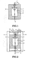
- a metal mold for resin molding of this type is divided into two parts shown on the left and on the right in the Figure, namely, a first metal mold 1 and a second metal mold 2.
- an injection port 5 for injection of epoxy resin 3 into the cavity 4 is provided at the lower part as shown in this Figure and an exhaust port 6 is provided at the upper part in this Figure.
- a movable valve 7 such as to float on the epoxy resin 3 is provided so as to be freely movable in the vertical direction as shown in the Figure.
- the movable valve 7 is freely detachable and is fixed to one or other of the metal molds 1 (2) by a support fitting 8 such as to permit free movement thereof in the vertical direction in the Figure.
- the first metal mold 1 and second metal mold 2 are closed, and are arranged in a prescribed vacuum of for example pressure 150 Pa.
- the movable valve 7 is positioned at the lower part in the Figure below the exhaust port 6, due to its own weight, the exhaust port 6 being in an opened condition and the interior of the cavity 4 being under vacuum. Then, when liquid epoxy resin 3 is injected from the injection port 5, the epoxy resin 3 in the cavity 4 fills the cavity towards the upper direction from below in the Figure, and any traces of air are extruded from the exhaust port 6.
- Epoxy resin 3 therefore cannot leak to outside the metal molds and 1 and 2.
- a molding of the desired shape is then obtained by applying a prescribed pressure of for example 300 kPa to the epoxy resin 3, thermal hardening, and releasing from the mold.
- a high-speed molding method wherein, as described in Laid-open Japanese Patent Application No. 2001-38774 , the first metal mold 1 and second metal mold 2 are raised to a high temperature of for example at least 120 °C and epoxy resin 3 is injected into the cavity 4 in a short time. Even in this high-speed molding method, traces of air can be extruded from the exhaust port 6 as described above, in order to suppress insulation defects such as voids.
- the air that is extruded to the exhaust port 6 may again be entrained into the cavity 4 by this random flow. If air is entrained into the cavity 4, voids, producing insulation defects, are formed, adversely affecting electrical properties such as partial discharge of the molding or mechanical properties such as the bending strength or tensile strength.
- the present invention was made in order to solve the problems described above, its object being to provide a metal mold for resin molding whereby moldings can be obtained with improved electrical and mechanical properties by positively accumulating the extruded air at the exhaust port.
- a metal mold for resin molding according to the present invention is constructed as follows. Specifically, a metal mold for resin molding comprises:
- Figure 2 is a cross-sectional view showing the construction of a metal mold for resin molding according to a first embodiment of the present invention
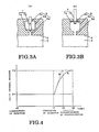
- Figure 3 shows detail cross-section views given in explanation of the operation of the movable valve of the metal mold for resin molding according to the first embodiment of present invention
- Figure 4 is a view given in explanation of the change of pressure of the epoxy resin in the cavity according to the first embodiment of the present invention. Structural parts that are the same as in the conventional metal mold are given the same reference symbols in the Figures.
- a metal mold for resin molding is divided into two parts shown on the left and on the right in the Figure, namely, a first metal mold 1 and a second metal mold 2.
- an injection port 5 for injection of epoxy resin 3 into the cavity 4 is provided at the lower part as shown in this Figure and an exhaust port 6 is provided at the upper part in this Figure.
- the exhaust port 6 comprises a small-diameter section 6a, a large-diameter intermediate section 6b connected with the cavity 4, and an exhaust section 6c that communicates with the outside.
- the large-diameter section 6b may be for example of tubular shape, dome shape or pillar shape. Moldings of prescribed shape are obtained using the cavity 4 formed by the metal molds 1 and 2.
- a movable valve 7 such as to float on the epoxy resin 3 is provided in the large-diameter section 6b of the exhaust port 6 so as to be freely movable in the vertical direction as shown in the Figure.
- the movable valve 7 comprises a floating section 7a and a pin section 7b:
- the floating section 7a comprises a resilient member having resilience, such as a spring plate or silicone rubber. Also, it may be made of thin plate shape comprising material such as fluorine-based resin, creating resilience, and may be heat resistant.
- the pin section 7b is freely detachable and is fixed to one or other of the metal molds 1 (2) by a support fitting 8 such as to permit free movement thereof in the axial direction.
- the first metal mold 1 is fixed to a first heating plate 10 in the left/right direction in the Figure and the second metal mold 2 is fixed to a second heating plate 11.
- One end of a vacuum enclosure 12 that can be used to evacuate the metal molds 1, 2 to vacuum is fixed to the second heating plate 11.
- a gasket 13 is provided at the other end of the vacuum enclosure 12 and is tightly fixed to the first heating plate 10.
- a resin injection pipe 14 for injection of epoxy resin 3 is detachably provided in airtight fashion at the injection port 5 in the lower part in the Figure of the vacuum enclosure 12.
- the first metal mold 1 and second metal mold 2 are firmly closed by a closing device, not shown, heated to for example a temperature of 180 °C, and the interior of the vacuum enclosure 12 is evacuated to a prescribed vacuum of for example pressure 150 Pa.
- a closing device not shown, heated to for example a temperature of 180 °C, and the interior of the vacuum enclosure 12 is evacuated to a prescribed vacuum of for example pressure 150 Pa.
- the floating section 7a of the movable valve 7 is positioned at the lower part in the Figure below the exhaust port 6, due to its own weight, the exhaust port 6 being in an opened condition and the interior of the cavity 4 being under vacuum.
- the resin injection pipe 14 is then connected with the injection port 5 and liquid epoxy resin 3 is injected.
- the interior of the cavity 4 is filled with epoxy resin 3 from the lower part in the Figure towards the upper part, residual air being extruded from the exhaust port 6. Since the diameter of this exhaust port 6 changes from the small-diameter section 6a to a large-diameter section 6b, the speed of the airflow passing through the small-diameter section 6a is fast, facilitating extrusion of residual air from within the cavity 4.
- the floating section 7a of the movable valve 7 floats on the epoxy resin 3 and moves in the upwards direction in the Figure through the large-diameter section 6b. This floating section 7a is then pressed onto the exhaust section 6c, so that the exhaust port 6 is thereby closed. After this closure, the epoxy resin 3 is pressurized to a prescribed pressure of for example 300 kPa. The floating section 7a of the movable valve 7 is deformed by this pressurization, being gradually bent into a bowl shape about the exhaust section 6c.
- the exhaust port 6 is closed, and injection is terminated.
- the flow of the epoxy resin 3 therefore does not tend to become turbulent and the epoxy resin 3 can easily be made to flow in a fixed direction towards the exhaust port 6 as shown in Figure 2. Consequently, entrainment of residual air in the vicinity of the exhaust port 6 into the cavity 4 can be suppressed.
- the epoxy resin 3 undergoes thermal hardening in the cavity 4, and, when released from the mold after hardening, a molding in which insulation defects are suppressed can be obtained.
- the epoxy resin 3 that hardens at the exhaust port 6 and injection port 5 is removed by mechanical processing after release from the mold.
- pressurization is discontinued at a time t3 that is shorter than the time t2 after completion of injection at the time t1. Since, with this mode of pressure change, there is an abrupt rise in pressure, followed by a sudden discontinuance at the time t3, the direction of flow of the epoxy resin 3 easily becomes random. In particular, in the high-speed injection method, there is shorter time between pressurization and discontinuance of pressurization, so the flow of epoxy resin 3 can easily become turbulent. However, since the change of pressure occurs more gradually whilst the movable valve 7 is being deformed, disturbance of the direction of flow of the epoxy resin 3 is unlikely, which is more suitable for a high-speed molding method.
- the length of the small-diameter section 6a of the exhaust port 6 is 10 mm to 50 mm. This is because, if the length of the small-diameter section 6a is less than 10 mm, epoxy resin 3, whose viscosity has become low, flows into the large-diameter section 6b from the cavity 4 in a short time, so the effect of extruding residual air is small; but if the length of the small-diameter section 6a is more than 50 mm, the viscosity of the epoxy resin 3 in the small-diameter section 6a rises, making it difficult to control the pressure within the cavity 4.
- a movable valve 7 that closes this exhaust port 6 while being bent by the pressurization of the epoxy resin 3 is provided at the exhaust port 6 provided by the first metal mold 1 and second metal mold 2. Consequently, the change in pressure of pressurization and discontinuance of pressurization of the epoxy resin 3 in the cavity 4 is made gradual, so entrainment of air that was extruded from the cavity 4 back into the cavity 4 can be suppressed, making it possible to obtain moldings of improved electrical and mechanical properties.
- Figure 5 is a detail cross-sectional view of a metal mold for resin molding according to a second embodiment of the present invention.
- the movable valve 7 has a pin 7b and hollow floating section 7c.
- the floating section 7c comprises a resilient member having resilience being made for example of silicone rubber, that is capable of free movement within the large-diameter section 6b of the exhaust port 6.
- this hollow section is deformed into an oval shape.
- processing costs can be reduced by making the floating section 7d dome-shaped. Forming an air reservoir 15 between the interior of the dome of the floating section 7d and the resin 3 ensures that buoyancy is not lost.
Landscapes
- Engineering & Computer Science (AREA)
- Mechanical Engineering (AREA)
- Manufacturing & Machinery (AREA)
- Casting Or Compression Moulding Of Plastics Or The Like (AREA)
- Moulds For Moulding Plastics Or The Like (AREA)
Applications Claiming Priority (1)
| Application Number | Priority Date | Filing Date | Title |
|---|---|---|---|
| JP2005319825A JP4768401B2 (ja) | 2005-11-02 | 2005-11-02 | 樹脂注型金型 |
Publications (2)
| Publication Number | Publication Date |
|---|---|
| EP1782935A1 true EP1782935A1 (fr) | 2007-05-09 |
| EP1782935B1 EP1782935B1 (fr) | 2010-09-29 |
Family
ID=37734766
Family Applications (1)
| Application Number | Title | Priority Date | Filing Date |
|---|---|---|---|
| EP06022755A Ceased EP1782935B1 (fr) | 2005-11-02 | 2006-10-31 | Moule métallique pour moulage de résine |
Country Status (5)
| Country | Link |
|---|---|
| EP (1) | EP1782935B1 (fr) |
| JP (1) | JP4768401B2 (fr) |
| KR (1) | KR100790509B1 (fr) |
| CN (1) | CN101024297B (fr) |
| DE (1) | DE602006017154D1 (fr) |
Cited By (4)
| Publication number | Priority date | Publication date | Assignee | Title |
|---|---|---|---|---|
| US7833003B2 (en) * | 2008-01-28 | 2010-11-16 | Kabushiki Kaisha Saito Kanagata Seisakusho | In-mold degassing structure and mold having the structure |
| WO2011095263A1 (fr) * | 2010-02-02 | 2011-08-11 | Robert Bosch Gmbh | Dispositif de fabrication d'éléments présentant un surmoulage en matière plastique et élément surmoulé |
| WO2011097009A2 (fr) | 2010-02-02 | 2011-08-11 | Dow Global Technologies Llc | Compositions de résine époxy durcissables |
| ITRM20120616A1 (it) * | 2012-12-05 | 2014-06-06 | Bridgestone Europ Nv | Valvola di sfogo per uno stampo di vulcanizzazione per pneumatici |
Families Citing this family (3)
| Publication number | Priority date | Publication date | Assignee | Title |
|---|---|---|---|---|
| CN101270220B (zh) * | 2008-04-30 | 2011-04-06 | 海洋化工研究院 | 聚合物基轻质耐压浮力材料的制备方法及设备 |
| JP2012030536A (ja) * | 2010-07-30 | 2012-02-16 | Toshiba Corp | 注形用金型及びガス絶縁開閉装置 |
| KR102989885B1 (ko) | 2022-02-14 | 2026-07-10 | 효성중공업 주식회사 | 고속 금형장치 |
Citations (13)
| Publication number | Priority date | Publication date | Assignee | Title |
|---|---|---|---|---|
| US2290510A (en) * | 1937-02-22 | 1942-07-21 | Talalay Josef Anton | Apparatus for molding spongelike articles |
| US3892508A (en) * | 1972-09-29 | 1975-07-01 | Fritz Hodler | Casting mould having a ventilation duct |
| DE2524538A1 (de) * | 1975-06-03 | 1976-12-16 | Continental Gummi Werke Ag | Spritzgiessform zum herstellen von gummi- oder kunststoffartikeln |
| JPS56123811A (en) * | 1980-03-06 | 1981-09-29 | Ube Ind Ltd | Degassing apparatus for die |
| JPS56127439A (en) * | 1980-03-11 | 1981-10-06 | Yokohama Rubber Co Ltd:The | Molding die for rubber product |
| JPS60127112A (ja) * | 1983-12-14 | 1985-07-06 | Matsushita Electric Works Ltd | 成形金型のエア抜き装置 |
| JPH02209214A (ja) * | 1989-02-10 | 1990-08-20 | Teijin Ltd | Rim成形金型のガス抜き装置 |
| JPH04156321A (ja) * | 1990-10-19 | 1992-05-28 | Toyoda Gosei Co Ltd | 成形用金型 |
| JPH0564820A (ja) * | 1991-09-06 | 1993-03-19 | Toshiba Corp | 注型金型 |
| EP0842749A1 (fr) * | 1996-11-15 | 1998-05-20 | Dunlop Tyres Ltd | Events pour moules |
| JP2000015668A (ja) * | 1998-07-06 | 2000-01-18 | Canon Inc | 射出成形用金型 |
| EP1074367A2 (fr) * | 1999-08-03 | 2001-02-07 | Kabushiki Kaisha Toshiba | Dispositif et procédé de coulage d'article moulés en résine epoxy |
| DE10033702A1 (de) * | 1999-07-12 | 2001-05-17 | Toshiba Kawasaki Kk | Gießvorrichtung |
Family Cites Families (3)
| Publication number | Priority date | Publication date | Assignee | Title |
|---|---|---|---|---|
| JPS58138613A (ja) * | 1982-02-13 | 1983-08-17 | Mitsubishi Electric Corp | 注型金型装置 |
| JP3255505B2 (ja) * | 1993-09-07 | 2002-02-12 | 株式会社東芝 | 真空金型 |
| JP2003089124A (ja) * | 2001-09-19 | 2003-03-25 | Kanto Auto Works Ltd | 真空注型用樹脂注入装置 |
-
2005
- 2005-11-02 JP JP2005319825A patent/JP4768401B2/ja not_active Expired - Lifetime
-
2006
- 2006-10-31 EP EP06022755A patent/EP1782935B1/fr not_active Ceased
- 2006-10-31 DE DE602006017154T patent/DE602006017154D1/de active Active
- 2006-11-01 KR KR1020060107201A patent/KR100790509B1/ko not_active Expired - Fee Related
- 2006-11-02 CN CN2006100644733A patent/CN101024297B/zh active Active
Patent Citations (14)
| Publication number | Priority date | Publication date | Assignee | Title |
|---|---|---|---|---|
| US2290510A (en) * | 1937-02-22 | 1942-07-21 | Talalay Josef Anton | Apparatus for molding spongelike articles |
| US3892508A (en) * | 1972-09-29 | 1975-07-01 | Fritz Hodler | Casting mould having a ventilation duct |
| DE2524538A1 (de) * | 1975-06-03 | 1976-12-16 | Continental Gummi Werke Ag | Spritzgiessform zum herstellen von gummi- oder kunststoffartikeln |
| JPS56123811A (en) * | 1980-03-06 | 1981-09-29 | Ube Ind Ltd | Degassing apparatus for die |
| JPS56127439A (en) * | 1980-03-11 | 1981-10-06 | Yokohama Rubber Co Ltd:The | Molding die for rubber product |
| JPS60127112A (ja) * | 1983-12-14 | 1985-07-06 | Matsushita Electric Works Ltd | 成形金型のエア抜き装置 |
| JPH02209214A (ja) * | 1989-02-10 | 1990-08-20 | Teijin Ltd | Rim成形金型のガス抜き装置 |
| JPH04156321A (ja) * | 1990-10-19 | 1992-05-28 | Toyoda Gosei Co Ltd | 成形用金型 |
| JPH0564820A (ja) * | 1991-09-06 | 1993-03-19 | Toshiba Corp | 注型金型 |
| EP0842749A1 (fr) * | 1996-11-15 | 1998-05-20 | Dunlop Tyres Ltd | Events pour moules |
| JP2000015668A (ja) * | 1998-07-06 | 2000-01-18 | Canon Inc | 射出成形用金型 |
| DE10033702A1 (de) * | 1999-07-12 | 2001-05-17 | Toshiba Kawasaki Kk | Gießvorrichtung |
| EP1074367A2 (fr) * | 1999-08-03 | 2001-02-07 | Kabushiki Kaisha Toshiba | Dispositif et procédé de coulage d'article moulés en résine epoxy |
| JP2001038744A (ja) * | 1999-08-03 | 2001-02-13 | Toshiba Corp | 注型装置、離型装置、及び保護治具 |
Cited By (4)
| Publication number | Priority date | Publication date | Assignee | Title |
|---|---|---|---|---|
| US7833003B2 (en) * | 2008-01-28 | 2010-11-16 | Kabushiki Kaisha Saito Kanagata Seisakusho | In-mold degassing structure and mold having the structure |
| WO2011095263A1 (fr) * | 2010-02-02 | 2011-08-11 | Robert Bosch Gmbh | Dispositif de fabrication d'éléments présentant un surmoulage en matière plastique et élément surmoulé |
| WO2011097009A2 (fr) | 2010-02-02 | 2011-08-11 | Dow Global Technologies Llc | Compositions de résine époxy durcissables |
| ITRM20120616A1 (it) * | 2012-12-05 | 2014-06-06 | Bridgestone Europ Nv | Valvola di sfogo per uno stampo di vulcanizzazione per pneumatici |
Also Published As
| Publication number | Publication date |
|---|---|
| CN101024297A (zh) | 2007-08-29 |
| DE602006017154D1 (de) | 2010-11-11 |
| JP4768401B2 (ja) | 2011-09-07 |
| KR20070047713A (ko) | 2007-05-07 |
| EP1782935B1 (fr) | 2010-09-29 |
| KR100790509B1 (ko) | 2008-01-02 |
| JP2007125771A (ja) | 2007-05-24 |
| CN101024297B (zh) | 2010-06-09 |
Similar Documents
| Publication | Publication Date | Title |
|---|---|---|
| CN106975738B (zh) | 真空压铸设备和高真空压铸方法 | |
| CN107548341B (zh) | 纤维增强塑料成型体的制造方法 | |
| JP6072250B2 (ja) | 容器を製造する方法および装置 | |
| EP1782935B1 (fr) | Moule métallique pour moulage de résine | |
| CN105579217A (zh) | 将附件安装在储箱壁上的安装方法 | |
| CN101862782B (zh) | 一种大变径比的变径零件粘弹塑性软模成形方法 | |
| CN102490348A (zh) | 一种吹塑制品成型方法及其设备 | |
| CN115709548B (zh) | 成型装置及其注入成型方法 | |
| CN103692662A (zh) | 真空模腔柱塞高压浸渍模塑方法及装置 | |
| CN203637197U (zh) | 真空模腔柱塞高压浸渍模塑装置 | |
| KR101689529B1 (ko) | 다이캐스팅 장치 및 다이캐스팅 방법 | |
| CN101609738B (zh) | 用于高压电缆附件绝缘部分制造的成型模具 | |
| CN104416832A (zh) | 用于包胶注射工艺制造真空灭弧室包封的模具 | |
| CN105150559A (zh) | 一种中空复合材料制品的rtm成型工艺和成型模具 | |
| KR101450836B1 (ko) | 상하이동부를 포함하는 성형장치 | |
| SE501085C2 (sv) | Metod för tillverkning av kroppar av fiberkompositer | |
| CN104552803A (zh) | 中空制品注塑成型的方法 | |
| JP2003094459A (ja) | 注入成形金型及びこの金型を用いる成形品の製造法 | |
| CN223701203U (zh) | 精密陶瓷注塑成型装置 | |
| CN205343539U (zh) | 一种硅胶封口直管成型模具 | |
| CN104085044B (zh) | 一种利用中空陶瓷模具成型中空陶瓷构件的方法 | |
| CN201522896U (zh) | 用于高压电缆附件绝缘部分制造的成型模具 | |
| US20250360658A1 (en) | Molding die, injection molding apparatus, and method for producing resin molded product | |
| CN111016105B (zh) | 一种嵌件成型方法及装置 | |
| JP5987190B2 (ja) | 半導体装置封止用金型及び半導体装置 |
Legal Events
| Date | Code | Title | Description |
|---|---|---|---|
| PUAI | Public reference made under article 153(3) epc to a published international application that has entered the european phase |
Free format text: ORIGINAL CODE: 0009012 |
|
| 17P | Request for examination filed |
Effective date: 20061031 |
|
| AK | Designated contracting states |
Kind code of ref document: A1 Designated state(s): AT BE BG CH CY CZ DE DK EE ES FI FR GB GR HU IE IS IT LI LT LU LV MC NL PL PT RO SE SI SK TR |
|
| AX | Request for extension of the european patent |
Extension state: AL BA HR MK YU |
|
| 17Q | First examination report despatched |
Effective date: 20060713 |
|
| R17C | First examination report despatched (corrected) |
Effective date: 20070713 |
|
| AKX | Designation fees paid |
Designated state(s): DE FR |
|
| GRAP | Despatch of communication of intention to grant a patent |
Free format text: ORIGINAL CODE: EPIDOSNIGR1 |
|
| GRAS | Grant fee paid |
Free format text: ORIGINAL CODE: EPIDOSNIGR3 |
|
| GRAA | (expected) grant |
Free format text: ORIGINAL CODE: 0009210 |
|
| AK | Designated contracting states |
Kind code of ref document: B1 Designated state(s): DE FR |
|
| REF | Corresponds to: |
Ref document number: 602006017154 Country of ref document: DE Date of ref document: 20101111 Kind code of ref document: P |
|
| PLBE | No opposition filed within time limit |
Free format text: ORIGINAL CODE: 0009261 |
|
| STAA | Information on the status of an ep patent application or granted ep patent |
Free format text: STATUS: NO OPPOSITION FILED WITHIN TIME LIMIT |
|
| REG | Reference to a national code |
Ref country code: DE Ref legal event code: R097 Ref document number: 602006017154 Country of ref document: DE Effective date: 20110630 |
|
| REG | Reference to a national code |
Ref country code: FR Ref legal event code: PLFP Year of fee payment: 11 |
|
| REG | Reference to a national code |
Ref country code: FR Ref legal event code: PLFP Year of fee payment: 12 |
|
| REG | Reference to a national code |
Ref country code: FR Ref legal event code: PLFP Year of fee payment: 13 |
|
| PGFP | Annual fee paid to national office [announced via postgrant information from national office to epo] |
Ref country code: DE Payment date: 20191015 Year of fee payment: 14 |
|
| PGFP | Annual fee paid to national office [announced via postgrant information from national office to epo] |
Ref country code: FR Payment date: 20200914 Year of fee payment: 15 |
|
| REG | Reference to a national code |
Ref country code: DE Ref legal event code: R119 Ref document number: 602006017154 Country of ref document: DE |
|
| PG25 | Lapsed in a contracting state [announced via postgrant information from national office to epo] |
Ref country code: DE Free format text: LAPSE BECAUSE OF NON-PAYMENT OF DUE FEES Effective date: 20210501 |
|
| PG25 | Lapsed in a contracting state [announced via postgrant information from national office to epo] |
Ref country code: FR Free format text: LAPSE BECAUSE OF NON-PAYMENT OF DUE FEES Effective date: 20211031 |