EP1782992B1 - Überrollventil mit Unterdrucksicherheitsfunktion - Google Patents
Überrollventil mit Unterdrucksicherheitsfunktion Download PDFInfo
- Publication number
- EP1782992B1 EP1782992B1 EP20060255088 EP06255088A EP1782992B1 EP 1782992 B1 EP1782992 B1 EP 1782992B1 EP 20060255088 EP20060255088 EP 20060255088 EP 06255088 A EP06255088 A EP 06255088A EP 1782992 B1 EP1782992 B1 EP 1782992B1
- Authority
- EP
- European Patent Office
- Prior art keywords
- valve
- fluid
- inlet
- outlet
- pressure
- Prior art date
- Legal status (The legal status is an assumption and is not a legal conclusion. Google has not performed a legal analysis and makes no representation as to the accuracy of the status listed.)
- Active
Links
Images

Classifications
-
- F—MECHANICAL ENGINEERING; LIGHTING; HEATING; WEAPONS; BLASTING
- F02—COMBUSTION ENGINES; HOT-GAS OR COMBUSTION-PRODUCT ENGINE PLANTS
- F02M—SUPPLYING COMBUSTION ENGINES IN GENERAL WITH COMBUSTIBLE MIXTURES OR CONSTITUENTS THEREOF
- F02M25/00—Engine-pertinent apparatus for adding non-fuel substances or small quantities of secondary fuel to combustion-air, main fuel or fuel-air mixture
- F02M25/08—Engine-pertinent apparatus for adding non-fuel substances or small quantities of secondary fuel to combustion-air, main fuel or fuel-air mixture adding fuel vapours drawn from engine fuel reservoir
-
- F—MECHANICAL ENGINEERING; LIGHTING; HEATING; WEAPONS; BLASTING
- F16—ENGINEERING ELEMENTS AND UNITS; GENERAL MEASURES FOR PRODUCING AND MAINTAINING EFFECTIVE FUNCTIONING OF MACHINES OR INSTALLATIONS; THERMAL INSULATION IN GENERAL
- F16K—VALVES; TAPS; COCKS; ACTUATING-FLOATS; DEVICES FOR VENTING OR AERATING
- F16K17/00—Safety valves; Equalising valves, e.g. pressure relief valves
- F16K17/36—Safety valves; Equalising valves, e.g. pressure relief valves actuated in consequence of extraneous circumstances, e.g. shock, change of position
-
- B—PERFORMING OPERATIONS; TRANSPORTING
- B60—VEHICLES IN GENERAL
- B60K—ARRANGEMENT OR MOUNTING OF PROPULSION UNITS OR OF TRANSMISSIONS IN VEHICLES; ARRANGEMENT OR MOUNTING OF PLURAL DIVERSE PRIME-MOVERS IN VEHICLES; AUXILIARY DRIVES FOR VEHICLES; INSTRUMENTATION OR DASHBOARDS FOR VEHICLES; ARRANGEMENTS IN CONNECTION WITH COOLING, AIR INTAKE, GAS EXHAUST OR FUEL SUPPLY OF PROPULSION UNITS IN VEHICLES
- B60K15/00—Arrangement in connection with fuel supply of combustion engines or other fuel consuming energy converters, e.g. fuel cells; Mounting or construction of fuel tanks
- B60K15/03—Fuel tanks
- B60K15/035—Fuel tanks characterised by venting means
-
- F—MECHANICAL ENGINEERING; LIGHTING; HEATING; WEAPONS; BLASTING
- F16—ENGINEERING ELEMENTS AND UNITS; GENERAL MEASURES FOR PRODUCING AND MAINTAINING EFFECTIVE FUNCTIONING OF MACHINES OR INSTALLATIONS; THERMAL INSULATION IN GENERAL
- F16K—VALVES; TAPS; COCKS; ACTUATING-FLOATS; DEVICES FOR VENTING OR AERATING
- F16K24/00—Devices, e.g. valves, for venting or aerating enclosures
- F16K24/04—Devices, e.g. valves, for venting or aerating enclosures for venting only
- F16K24/042—Devices, e.g. valves, for venting or aerating enclosures for venting only actuated by a float
-
- B—PERFORMING OPERATIONS; TRANSPORTING
- B60—VEHICLES IN GENERAL
- B60K—ARRANGEMENT OR MOUNTING OF PROPULSION UNITS OR OF TRANSMISSIONS IN VEHICLES; ARRANGEMENT OR MOUNTING OF PLURAL DIVERSE PRIME-MOVERS IN VEHICLES; AUXILIARY DRIVES FOR VEHICLES; INSTRUMENTATION OR DASHBOARDS FOR VEHICLES; ARRANGEMENTS IN CONNECTION WITH COOLING, AIR INTAKE, GAS EXHAUST OR FUEL SUPPLY OF PROPULSION UNITS IN VEHICLES
- B60K15/00—Arrangement in connection with fuel supply of combustion engines or other fuel consuming energy converters, e.g. fuel cells; Mounting or construction of fuel tanks
- B60K15/03—Fuel tanks
- B60K15/035—Fuel tanks characterised by venting means
- B60K15/03519—Valve arrangements in the vent line
-
- Y—GENERAL TAGGING OF NEW TECHNOLOGICAL DEVELOPMENTS; GENERAL TAGGING OF CROSS-SECTIONAL TECHNOLOGIES SPANNING OVER SEVERAL SECTIONS OF THE IPC; TECHNICAL SUBJECTS COVERED BY FORMER USPC CROSS-REFERENCE ART COLLECTIONS [XRACs] AND DIGESTS
- Y10—TECHNICAL SUBJECTS COVERED BY FORMER USPC
- Y10T—TECHNICAL SUBJECTS COVERED BY FORMER US CLASSIFICATION
- Y10T137/00—Fluid handling
- Y10T137/0753—Control by change of position or inertia of system
- Y10T137/0874—Vent opening or closing on tipping container
-
- Y—GENERAL TAGGING OF NEW TECHNOLOGICAL DEVELOPMENTS; GENERAL TAGGING OF CROSS-SECTIONAL TECHNOLOGIES SPANNING OVER SEVERAL SECTIONS OF THE IPC; TECHNICAL SUBJECTS COVERED BY FORMER USPC CROSS-REFERENCE ART COLLECTIONS [XRACs] AND DIGESTS
- Y10—TECHNICAL SUBJECTS COVERED BY FORMER USPC
- Y10T—TECHNICAL SUBJECTS COVERED BY FORMER US CLASSIFICATION
- Y10T137/00—Fluid handling
- Y10T137/2931—Diverse fluid containing pressure systems
- Y10T137/3003—Fluid separating traps or vents
- Y10T137/3084—Discriminating outlet for gas
- Y10T137/309—Fluid sensing valve
- Y10T137/3099—Float responsive
-
- Y—GENERAL TAGGING OF NEW TECHNOLOGICAL DEVELOPMENTS; GENERAL TAGGING OF CROSS-SECTIONAL TECHNOLOGIES SPANNING OVER SEVERAL SECTIONS OF THE IPC; TECHNICAL SUBJECTS COVERED BY FORMER USPC CROSS-REFERENCE ART COLLECTIONS [XRACs] AND DIGESTS
- Y10—TECHNICAL SUBJECTS COVERED BY FORMER USPC
- Y10T—TECHNICAL SUBJECTS COVERED BY FORMER US CLASSIFICATION
- Y10T137/00—Fluid handling
- Y10T137/7722—Line condition change responsive valves
- Y10T137/7771—Bi-directional flow valves
- Y10T137/7779—Axes of ports parallel
-
- Y—GENERAL TAGGING OF NEW TECHNOLOGICAL DEVELOPMENTS; GENERAL TAGGING OF CROSS-SECTIONAL TECHNOLOGIES SPANNING OVER SEVERAL SECTIONS OF THE IPC; TECHNICAL SUBJECTS COVERED BY FORMER USPC CROSS-REFERENCE ART COLLECTIONS [XRACs] AND DIGESTS
- Y10—TECHNICAL SUBJECTS COVERED BY FORMER USPC
- Y10T—TECHNICAL SUBJECTS COVERED BY FORMER US CLASSIFICATION
- Y10T137/00—Fluid handling
- Y10T137/7722—Line condition change responsive valves
- Y10T137/7837—Direct response valves [i.e., check valve type]
- Y10T137/7879—Resilient material valve
Definitions
- the present invention relates to a roll over vent valve designed to allow, on the one hand, for the venting of fuel vapor from a vehicle fuel tank to the atmosphere or rather to a vapor recovery system such as a carbon canister, and, on the other hand, to ensure the closure of the valve under certain conditions.
- a vapor recovery system such as a carbon canister
- the valve of the present invention also permits airing the fuel tank at a substantially high flow-rate.
- pressure drop within the fuel tank may result in damaging of the fuel tank (e.g. cracking thereof).
- Pressure drop within the fuel tank may occur, for expel as a result of increased fuel consumption (e.g. during acceleration of the vehicle) and during drop of temperature and pressure changes (e.g. change of altitude).
- the invention calls for a fuel valve for fitting in a vehicle's fuel tank, wherein an outlet port of the valve is typically coupled to a fuel treating device, e.g. a fuel canister.
- a fuel treating device e.g. a fuel canister.
- the valve according to the present invention is designed so as to allow for airing of the fuel tank upon under-pressure (vacuum) in the fuel tank, to thereby prevent damage thereof (bucking, cracking opening of wealds, etc.) which may cause fuel leaks, resulting in severe safety and environmental consequences.
- Under-pressure within the fuel tank may occur for example due to increased fuel consumption by the vehicle's engine (e.g. upon accelerating or going uphill), upon temperature changes where the fuel tank may shrink at cold temperatures, or upon pressure changes at different altitudes, etc.
- the one-way inlet valve is in the form of a cage and comprises a sealing member received within the cage and being displaceable between sealing engagement of the inlet port and disengagement therefrom at under-pressure conditions at the fluid inlet.
- the sealing member of the one-way inlet valve is a flexible seal whereby at the event of under-pressure at the fluid inlet the flexible seal disengages from the inlet port and deforms so as to increase the flow section area through the inlet port.
- the design of the valve is such that the inlet port of the one-way inlet valve is in flow communication with the fluid outlet of the valve through venting ducts overriding the pressure-retention device.
- the pressure-retaining device may be a disc-type pressure retainer (spring biased, or not), a ball-type pressure retainer, or any other suitable pressure retaining device.
- the inlet port of the cage is formed at a wall portion of the housing and the outlet port of the cage is formed at a cage closure fixed to the housing, wherein said outlet port is in flow communication with the fluid inlet of the valve.
- the one-way inlet valve extends offset with respect to a longitudinal axis of the valve.
- the one-way inlet valve is sealable regardless the position of the float member within the housing. Accordingly, the one-way valve may open to vent the fuel tank regardless if the float member is in its uppermost sealing position, i.e. whereby the sealing member sealingly bears against the valve seating of the outlet, or when the float member descends to its open position wherein the sealing member is disengaged from the valve seating.
- the one-way inlet valve is designed for airing the valve at substantially high flow rate, of up to about 4 l/min.
- the arrangement is such that the one-way inlet valve spontaneously seals at the event of rollover of the vehicle.
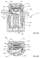
- FIG. 1 there is illustrated a perspective view of the valve in accordance with the present invention generally designated 10, the valve comprising a cylindrical housing 12 formed with a flanged upper portion 14 adapted for welding (heat welding) within an aperture formed at an upper wall of a fuel tank (not shown) with only a top head portion 16 projecting therefrom, with a fuel outlet nozzle 18 extending therefrom and connectable to a fuel vapor treating device, e.g. canister (not shown).
- a fuel vapor treating device e.g. canister
- the housing 12 is formed with several fluid inlet apertures 22 at a bottom portion thereof.
- a float member 26 which owing to longitudinal ribs 28 formed on the outer surface of float member 26, and corresponding recesses 32 formed on the inside surface of the housing 12, the float member 26 is restricted to only axially displacement within the housing, without the ability to angularly (rotationally) displace therewithin.
- a coiled spring 34 is provided, said spring bearing at a lower end thereof against a tubular spring support 36 of the housing and at an upper end thereof against a spring seat 38 within a float retention cylinder 40, thereby biasing the float member 26 in an upper direction.
- An elongated, strip-like, flexible membrane 42 is anchored at one end thereof 44 by means of an anchoring stud 46 to an upper wall of the float member 26, which is offset with respect to the longitudinal access of the housing 12 and with respect to an outlet 48 being in flow communication with a space 50 at the top portion 16 of the float and thus with the outlet nozzle 18 ( Fig. 1 ).
- Outlet 48 has a downwardly depending valve seating 56, formed at its lower-most end with an inclined, elongated outlet aperture 60 sealingly engageable by the strip-like, flexible membrane sealing member 42.
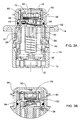
- Float member 26 is biased upwardly into sealing engagement of the fluid outlet by means of the compression spring 34 which acts together with inherent buoyancy of the float member 26. These upwardly-directed forces (buoyancy and spring biasing) tend to seal the slit-like outlet aperture 56 by said sealing strip-like sealing member 42 as seen in the position of Fig. 3A .
- the outlet chamber 50 comprises, above the fluid outlet 48, a pressure retention disk 70 which normally bears against a rimmed seating 72 of the downwardly depending fluid outlet funnel 48.
- the arrangement is such that the pressure retention disk 70 is displaceable between a closed position ( Figs. 3A and 3B ) wherein it sealingly bears against the rim 72 to allow for a predetermined pressure buildup within the fuel tank (typically about 3 to 4 KPA, not shown) so as to shut off the sealing process upon sensing such pressure buildup within the fuel tank, as known per se.
- a predetermined pressure buildup within the fuel tank typically about 3 to 4 KPA, not shown
- the pressure retention disk 70 will disengage from the sealing rim 72 (see Fig.
- the pressure-retaining device may be a disc-type pressure retainer (spring biased, or not), a ball-type pressure retainer, or any other suitable pressure retaining device.
- the funnel shaped fluid outlet 48 there is a one-way inlet valve ( Figs. 2B and 3B ) comprising a cage structure 80 constituting of an upper wall portion 82 being part of the inside housing of the valve, and a bottom support member 84 fixedly attached thereto, e.g. by heat welding, sonic welding, etc., forming a space 86 within the cage 80.
- the cage 80 is formed with an inlet port 90 being in flow communication with the upper space 50 of the valve, by means of venting ducts 94 overriding the pressure-retention disk 70 whereby the inlet port 90 is in flow communication with the fluid outlet nozzle 18 ( Fig. 1 ) of the valve.
- An outlet port 98 is formed in the closure member 84 of the cage 80 , said outlet port 98 being in flow communication with the fluid inlet apertures 22 of the valve.
- a sealing member 100 in the form of a resilient seal (rectangle according to the present example and being sufficiently thin to maintain flexibility) displaceable within the cage 80 between sealing engagement of the inlet port 90 ( Fig. 2B , and disengagement thereof, as seen in the position of Fig. 3B ). Furthermore, owing to its resiliency, the sealing member 100 will not only displace from sealing engagement of the inlet port 90 , it will also deform so as to increase the effective section area of the inlet port 90 , to increase the flow rate into the valve and consequently into the fuel tank (not shown), at a flow rate of at of up to about 4 liters per minute.
- the pressure-retention disk 70 is in its closed position, namely bearing against sealing rim 72 , so as to allow for pressure built within the fuel tank (to about 3 to 4 KPA) so as to shut off a fuel pump (not shown) and prevent refueling, as known in the art.
- Figs. 2B and 3B it is illustrated how the one-way inlet valve cooperates with the roll-over vent valve of the present invention.
- the sealing diaphragm 100 In the normal condition of the valve, when pressure within the fuel tank is maintained within predetermined pressure values (namely as long as the fuel tank is not at under pressure (vacuum); as already discussed hereinabove, over pressure of up to about 3 to 4 KPA is desired so as to prevent refueling) the sealing diaphragm 100 is in its sealed position of Fig. 2B , namely sealing the inlet port 90 to prevent fluid flow therethrough, in either direction, such that the roll-over vent functions as discussed hereinabove in conjunction with the pressure-retention disk.
- the elasticity of the sealing member 100 together with the structure of the support member of cage 80 tend to retain the sealing member 100 sealingly engaged with the inlet port 90 of the one-way valve ( Fig. 2B ).
- the sealing strip 100 detaches from the inlet port 90 ( Fig. 3B ) and it also deforms so as to increase the throughflow section area of the inlet port 90, to thus allow venting of the fuel tank at a substantially high flow rate, e.g. up to about 4 liters per minute.
- the one-way inlet valve will spontaneously displace into its closed position ( Fig. 2B ) whereby fluid discharge is taken care of by means of the main fluid outlet 48 of the valve 10.
Landscapes
- Engineering & Computer Science (AREA)
- General Engineering & Computer Science (AREA)
- Mechanical Engineering (AREA)
- Chemical & Material Sciences (AREA)
- Combustion & Propulsion (AREA)
- Life Sciences & Earth Sciences (AREA)
- Sustainable Development (AREA)
- Sustainable Energy (AREA)
- Transportation (AREA)
- Cooling, Air Intake And Gas Exhaust, And Fuel Tank Arrangements In Propulsion Units (AREA)
- Self-Closing Valves And Venting Or Aerating Valves (AREA)
- Multiple-Way Valves (AREA)
Claims (9)
- Überschlag-Entlüftungsventil (10), das umfasst: ein Gehäuse (12), das mit einem Fluideinlass (22) und einem Fluidauslass (48) ausgebildet ist, einen Ventilsitz (56), der eine Auslassöffnung (60) des Gehäuses (12) begrenzt, ein Schwimmerelement (26), das in dem Gehäuse (12) aufgenommen ist und zwischen einer verschlossenen Position, in dersich ein Dichtungselement (42) hiervon an dem Ventilsitz (56) der Auslassöffnung (60) dichtend abstützt, um den Fluidauslass (48) zu verschließen, und einer offenen Position, in der das Dichtungselement (42) nicht mit dem Ventilsitz (56) in Eingriff ist, so dass der Fluidauslass (48) mit dem Fluideinlass (22) in einer Strömungskommunikation steht, axial verlagerbar ist; eine Druckhaltevorrichtung (70), die sich zwischen dem Ventilsitz (56) und dem Fluidauslass (48) erstreckt, um dadurch eine Fluidströmung dazwischen so lange zu unterbrechen, wie eine Druckdifferenz zwischen dem Fluideinlass (22) und dem Fluidauslass (48) einen minimalen Druckschwellenwert nicht übersteigt; wobei das Ventil ferner umfasst: ein Einweg-Fluideinlassventil, das mit einem Einlassanschluss (90) ausgebildet ist, der mit dem Fluidauslass (48) in einer Strömungskommunikation steht und mit einem Auslassanschluss (98) ausgebildet ist, der mit dem Fluideinlass (22) in einer Strömungskommunikation steht, um zu ermöglichen, dass Fluid zu dem Fluideinlass mit einer im Wesentlichen hohen Strömungsrate strömt, falls am Fluideinlass ein Unterdruck herrscht; wobei das Ventil dadurch gekennzeichnet ist, dass das Einweg-Einlassventil die Form eines Käfigs (80) hat und ein Dichtungselement (100) umfasst, das in dem Käfig aufgenommen ist und zwischen einem verschließenden Eingriff mit dem Einlassanschluss (90) und einer Position ohne Eingriff damit verlagerbar ist, sobald der Druck an dem Fluideinlass unter den Druck am Fluidauslass sinkt.
- Überschlag-Entlüftungsventil nach Anspruch 1, wobei das Dichtungselement (100) des Einweg-Einlassventils eine flexible Dichtung ist, wodurch im Fall eines Unterdrucks an dem Fluideinlass die flexible Dichtung ihren Eingriff mit dem Einlassartschluss (90) löst und sich verformt, um die Strömungsciuerschnittsfläche durch den Einlassanschluss zu erhöhen.
- Überschlag-Entlüftungsventil nach Anspruch 1, wobei der Einlassanschluss des Einweg-Einlassventils mit dem Fluidauslass (48) des Ventils durch Entlüftungsrohre (94), die die Druckhaltevorrichtung (70) umgehen, in einer Strömungskommunikation steht.
- Überschlag-Entlüftungsventil nach Anspruch 1, wobei der Einlassanschluss (90) des Käfigs (80) an einem Wandabschnitt (82) des Gehäuses (12) ausgebildet ist und der Auslassanschluss (98) des Käfigs (80) an einem Käfigverschluss (84), der am Gehäuse befestigt ist, ausgebildet ist, wobei der Auslassanschluss (98) mit dem Fluideinlass (22) des Ventils in einer Strömungskommunikation steht.
- Überschlag-Entlüftungsventil nach Anspruch 1, wobei das Einweg-Einlassventil sich versetzt zu einer Längachse des Ventils erstreckt.
- Überschlag-Entlüftungsventil nach Anspruch 1, wobei das Einweg-Einlassventil unabhangig von der Position des Schwimmerelements in dem Gehäuse abdichtbar ist.
- Überschlag-Entlüfturtgsventil nach Anspruch 1, wobei das Einweg-Einlassventil entworfen ist, um das Ventil mit einer im Wesentlichen hohen Strömungsrate von bis zu etwa 4 l/Min zu entlüften.
- Überschlag-Entlüftungsventil nach Anspruch 1, wobei das Einweg-Einlassventil im Fall eines Überschlags eines Fahrzeugs spontan schließt.
- Überschlag-Entlüftungsventil nach Anspruch 1, wobei das Dichtungselement (100) die Form einer elastischen Dichtung hat, die einen rechtwinkligen Querschnitt besitzt.
Applications Claiming Priority (1)
| Application Number | Priority Date | Filing Date | Title |
|---|---|---|---|
| IL17182205 | 2005-11-08 |
Publications (2)
| Publication Number | Publication Date |
|---|---|
| EP1782992A1 EP1782992A1 (de) | 2007-05-09 |
| EP1782992B1 true EP1782992B1 (de) | 2011-11-23 |
Family
ID=37714293
Family Applications (1)
| Application Number | Title | Priority Date | Filing Date |
|---|---|---|---|
| EP20060255088 Active EP1782992B1 (de) | 2005-11-08 | 2006-10-02 | Überrollventil mit Unterdrucksicherheitsfunktion |
Country Status (7)
| Country | Link |
|---|---|
| US (1) | US8109285B2 (de) |
| EP (1) | EP1782992B1 (de) |
| JP (1) | JP2007132514A (de) |
| KR (1) | KR100846527B1 (de) |
| CN (1) | CN100455862C (de) |
| AT (1) | ATE534543T1 (de) |
| RU (1) | RU2403482C2 (de) |
Families Citing this family (32)
| Publication number | Priority date | Publication date | Assignee | Title |
|---|---|---|---|---|
| WO2006113756A2 (en) * | 2005-04-20 | 2006-10-26 | Be Intellectual Property, Inc. | Air vent valve for beverage makers |
| US8109285B2 (en) * | 2005-11-08 | 2012-02-07 | Raval A.C.S. Ltd. | Roll over vent valve |
| US7547300B2 (en) | 2006-04-12 | 2009-06-16 | Icu Medical, Inc. | Vial adaptor for regulating pressure |
| US7883499B2 (en) | 2007-03-09 | 2011-02-08 | Icu Medical, Inc. | Vial adaptors and vials for regulating pressure |
| WO2010022095A1 (en) | 2008-08-20 | 2010-02-25 | Icu Medical, Inc. | Anti-reflux vial adaptors |
| CN101382208B (zh) * | 2008-10-17 | 2010-06-02 | 汪永明 | 电机阀 |
| US8342453B2 (en) * | 2010-02-09 | 2013-01-01 | Thunder Bay Aircraft Leasing Inc. | System for airborne transport of flammable liquids |
| DE102010030456A1 (de) * | 2010-06-23 | 2011-12-29 | Alfmeier Präzision AG Baugruppen und Systemlösungen | Entlüftungsventil |
| EP2611639B1 (de) * | 2010-09-02 | 2014-10-15 | Raval A.C.S. LTD | Rollover-ventil |
| KR101923999B1 (ko) * | 2011-01-31 | 2018-11-30 | 라발 에이.씨.에스. 엘티디 | 연료 밸브 |
| US9434246B2 (en) | 2011-03-14 | 2016-09-06 | Raval A.C.S. Ltd. | Fuel valve |
| PT2744469T (pt) | 2011-08-18 | 2023-01-12 | Icu Medical Inc | Adaptadores de frasco reguladores de pressão |
| US9360872B2 (en) * | 2011-12-22 | 2016-06-07 | Eaton Corporation | Fuel tank vent valve assembly and method of assembly |
| AU2013207770B2 (en) | 2012-01-13 | 2017-09-14 | Icu Medical, Inc. | Pressure-regulating vial adaptors and methods |
| AU2013204180B2 (en) | 2012-03-22 | 2016-07-21 | Icu Medical, Inc. | Pressure-regulating vial adaptors |
| EP3552595B1 (de) | 2013-01-23 | 2023-09-13 | ICU Medical, Inc. | Druckregelungsadapter für eine phiole |
| US9089475B2 (en) | 2013-01-23 | 2015-07-28 | Icu Medical, Inc. | Pressure-regulating vial adaptors |
| CN110638645B (zh) | 2013-07-19 | 2022-10-18 | 伊库医学有限公司 | 压力调节流体输送系统和方法 |
| US9456701B2 (en) * | 2014-06-13 | 2016-10-04 | Aeris Technology LLC | Valve assembly for controlling fluid communication between fluid chambers, inflatable device, and method |
| CA2953229C (en) | 2014-06-20 | 2024-01-02 | Icu Medical, Inc. | Pressure-regulating vial adaptors |
| CA3012733C (en) | 2016-01-29 | 2023-09-12 | Icu Medical, Inc. | Pressure-regulating vial adaptors |
| CN105927789A (zh) * | 2016-06-30 | 2016-09-07 | 锐嘉(宜兴)科技有限公司 | 灭菌设备泄压装置 |
| ES3058184T3 (en) | 2016-09-30 | 2026-03-09 | Icu Medical Inc | Pressure-regulating vial access devices and methods |
| CN106382170A (zh) * | 2016-10-26 | 2017-02-08 | 江苏大学 | 一种具有自调节密封位置功能的内置坡度阀 |
| CN108223868B (zh) * | 2018-01-11 | 2023-09-26 | 何悦瑜 | 自动控制供水阀 |
| JP2021011841A (ja) * | 2019-07-04 | 2021-02-04 | 株式会社デンソー | 蒸発燃料処理装置の密閉弁 |
| JP7340038B2 (ja) * | 2019-12-24 | 2023-09-06 | 株式会社パイオラックス | 弁装置 |
| DE102020207834A1 (de) * | 2020-06-24 | 2021-12-30 | Alfmeier Präzision SE | Entlüftungsventil mit prallwand als schwappschutz |
| EP4253809A4 (de) * | 2020-11-26 | 2024-10-30 | Yingzhi Aiyi Intelligent Automotive Technologies (Jiaxing) Co., Ltd. | Ventil, multifunktionales kombinationsventil und cflv-ventil |
| CN113700917B (zh) * | 2021-08-18 | 2025-07-22 | 盈智皑壹智能汽车科技(嘉兴)有限公司 | 一种油箱排气阀 |
| KR102948608B1 (ko) * | 2021-09-23 | 2026-04-03 | 현대자동차주식회사 | 자동차 연료탱크의 연료 넘침 방지 장치 |
| CN114526957A (zh) * | 2022-02-28 | 2022-05-24 | 邢妍 | 一种企业用水质监测深层水体取样装置及其使用方法 |
Family Cites Families (38)
| Publication number | Priority date | Publication date | Assignee | Title |
|---|---|---|---|---|
| US3776256A (en) * | 1970-08-14 | 1973-12-04 | American Motors Corp | Fuel evaporative control system |
| US3889710A (en) * | 1972-11-07 | 1975-06-17 | Julien H Brost | Check valve with elastomeric valve element |
| IT971505B (it) * | 1972-12-04 | 1974-05-10 | Goglio L | Valvola di degasamento per conte nitori flessibili a chiusura erme tica e contenitore corredato della valvola |
| IT1060652B (it) * | 1976-05-20 | 1982-08-20 | Larga Spa | Valvola per lo sfogo dell aria da impianti o condotto con circolazione di liquidi sotto pressione specialmente caldaie o componenti di impianti di riscaldamento |
| JPS5845347Y2 (ja) | 1981-09-17 | 1983-10-14 | 北海道水道機材株式会社 | 自動吸気弁 |
| JPS59165346U (ja) | 1983-04-20 | 1984-11-06 | リズム自動車部品製造株式会社 | 吸排気弁付キヤツプ |
| IT208359Z2 (it) | 1986-11-18 | 1988-05-28 | Gilardini Spa | Valvola di sicurezza per serbatoi di carburante per autoveicoli |
| US4753262A (en) * | 1987-02-06 | 1988-06-28 | G.T. Products, Inc. | Fuel system vent valve having roll-over closure with improved re-opening action for venting |
| US4886089A (en) * | 1988-05-27 | 1989-12-12 | Gt Development Corporation | Gas venting valve for liquid tank |
| JPH0452547Y2 (de) | 1988-09-30 | 1992-12-10 | ||
| US4953583A (en) | 1989-03-24 | 1990-09-04 | Stant Inc. | Tank pressure control valve |
| JPH03117857U (de) | 1990-03-16 | 1991-12-05 | ||
| DE4213932C3 (de) | 1992-04-28 | 1998-07-09 | Kayser A Gmbh & Co Kg | Tankentlüftungsventil |
| JPH06147045A (ja) | 1992-10-30 | 1994-05-27 | Toyoda Gosei Co Ltd | 燃料遮断装置 |
| US5313977A (en) | 1992-11-12 | 1994-05-24 | G. T. Products, Inc. | Fluid-responsive vent control valve with peel-away opening action |
| US5590697A (en) | 1994-08-24 | 1997-01-07 | G. T. Products, Inc. | Onboard vapor recovery system with two-stage shutoff valve |
| US5511581A (en) * | 1994-10-31 | 1996-04-30 | Ligh; Jone Y. | Vent valve |
| IL112444A (en) * | 1995-01-25 | 1998-01-04 | Raviv Precision Injection Mold | Roll over vent valve |
| US5623969A (en) * | 1995-06-07 | 1997-04-29 | B. Braun Medical Inc. | Normally closed aspiration valve |
| US5566705A (en) | 1995-06-30 | 1996-10-22 | Stant Manufacturing Inc. | Snap-closure float valve assembly |
| JP3585076B2 (ja) * | 1996-07-30 | 2004-11-04 | 株式会社デンソー | 燃料漏れ防止弁 |
| KR100192483B1 (ko) * | 1996-12-02 | 1999-06-15 | 정몽규 | 연료탱크의 연료누출방지장치 |
| US5927315A (en) | 1996-12-02 | 1999-07-27 | Hyundai Motor Company | Fuel leakage prevention apparatus |
| JPH1113910A (ja) | 1997-06-20 | 1999-01-22 | Yoshinobu Toyomura | 逆止弁機構 |
| JP3914320B2 (ja) * | 1998-01-26 | 2007-05-16 | 株式会社ミクニ | 燃料遮断装置及びその燃料遮断装置の連結構造 |
| JPH11247730A (ja) | 1998-03-03 | 1999-09-14 | Kyosan Denki Kk | エバポ制御システム及びエバポ制御バルブ |
| DE19922453A1 (de) | 1998-05-16 | 2000-01-27 | Alfmeier Praezision Ag | Roll-Over-Ventil |
| IL128937A (en) * | 1999-03-11 | 2002-09-12 | Raval Agriculture Coop Soc Ltd | Multi functional valve |
| US6145539A (en) * | 1999-04-12 | 2000-11-14 | Snap-Tite Technologies, Inc. | Balanced coupling with pressure bleed |
| US6561211B2 (en) * | 2000-10-19 | 2003-05-13 | Stant Manufacturing Inc. | Fuel tank vent control valve |
| US6371146B1 (en) * | 2000-11-07 | 2002-04-16 | Eaton Corporation | Peelaway type rollover valve element |
| JP4736224B2 (ja) | 2001-04-16 | 2011-07-27 | 大日本印刷株式会社 | 機能カード用カード部材、およびこれを用いた機能カード |
| JP2003026266A (ja) | 2001-07-17 | 2003-01-29 | Yushin Giken Kk | 液体注出装置 |
| JP2003113953A (ja) | 2001-10-04 | 2003-04-18 | Kyosan Denki Co Ltd | 通気弁構造 |
| US7017599B2 (en) * | 2003-02-18 | 2006-03-28 | Keefer Neal L | Thermal relief vent and method of manufacturing the same |
| CN1688934B (zh) | 2003-02-27 | 2010-05-26 | 富士通微电子株式会社 | 半导体器件的制造方法 |
| JP3117857U (ja) | 2005-07-19 | 2006-01-12 | 有限会社中西樹脂工芸 | ファイル収納ラック |
| US8109285B2 (en) * | 2005-11-08 | 2012-02-07 | Raval A.C.S. Ltd. | Roll over vent valve |
-
2006
- 2006-09-19 US US11/523,012 patent/US8109285B2/en active Active
- 2006-09-21 RU RU2006133720A patent/RU2403482C2/ru active
- 2006-09-26 JP JP2006261213A patent/JP2007132514A/ja active Pending
- 2006-10-02 EP EP20060255088 patent/EP1782992B1/de active Active
- 2006-10-02 AT AT06255088T patent/ATE534543T1/de active
- 2006-11-07 CN CNB2006101444217A patent/CN100455862C/zh active Active
- 2006-11-08 KR KR1020060109982A patent/KR100846527B1/ko active Active
Also Published As
| Publication number | Publication date |
|---|---|
| JP2007132514A (ja) | 2007-05-31 |
| KR100846527B1 (ko) | 2008-07-15 |
| KR20070049588A (ko) | 2007-05-11 |
| CN1963275A (zh) | 2007-05-16 |
| ATE534543T1 (de) | 2011-12-15 |
| US8109285B2 (en) | 2012-02-07 |
| EP1782992A1 (de) | 2007-05-09 |
| RU2403482C2 (ru) | 2010-11-10 |
| RU2006133720A (ru) | 2008-03-27 |
| CN100455862C (zh) | 2009-01-28 |
| US20070102043A1 (en) | 2007-05-10 |
Similar Documents
| Publication | Publication Date | Title |
|---|---|---|
| US8109285B2 (en) | Roll over vent valve | |
| EP2016320B1 (de) | Kraftstoffentlüftungsventil und verbesserung davon | |
| US6918405B2 (en) | Fill limit vent valve | |
| US5738132A (en) | Roll over vent valve | |
| US8176935B2 (en) | Vapor recovery control valve | |
| US5044389A (en) | High volume fuel vapor release valve | |
| CN101782159B (zh) | 用于燃料箱的双功能阀 | |
| US6561211B2 (en) | Fuel tank vent control valve | |
| EP2611639B1 (de) | Rollover-ventil | |
| EP2686591B1 (de) | Brennstoffventil | |
| EP1415845A2 (de) | Beweglicher Kragen zur Aufnahme einer Zapfpistole für einen deckellosen Einfüllstutzen | |
| US20070000542A1 (en) | Fuel tank valve | |
| US20100139625A1 (en) | Vehicle fuel system and components thereof | |
| US6758235B2 (en) | Vapor control valve with a metallic sealing element |
Legal Events
| Date | Code | Title | Description |
|---|---|---|---|
| PUAI | Public reference made under article 153(3) epc to a published international application that has entered the european phase |
Free format text: ORIGINAL CODE: 0009012 |
|
| AK | Designated contracting states |
Kind code of ref document: A1 Designated state(s): AT BE BG CH CY CZ DE DK EE ES FI FR GB GR HU IE IS IT LI LT LU LV MC NL PL PT RO SE SI SK TR |
|
| AX | Request for extension of the european patent |
Extension state: AL BA HR MK YU |
|
| 17P | Request for examination filed |
Effective date: 20071010 |
|
| 17Q | First examination report despatched |
Effective date: 20071108 |
|
| AKX | Designation fees paid |
Designated state(s): AT BE BG CH CY CZ DE DK EE ES FI FR GB GR HU IE IS IT LI LT LU LV MC NL PL PT RO SE SI SK TR |
|
| GRAP | Despatch of communication of intention to grant a patent |
Free format text: ORIGINAL CODE: EPIDOSNIGR1 |
|
| RIN1 | Information on inventor provided before grant (corrected) |
Inventor name: VULKAN, OMER Inventor name: AKIAN, ILAN Inventor name: EHRMAN, MOSHE |
|
| GRAS | Grant fee paid |
Free format text: ORIGINAL CODE: EPIDOSNIGR3 |
|
| GRAA | (expected) grant |
Free format text: ORIGINAL CODE: 0009210 |
|
| RAP1 | Party data changed (applicant data changed or rights of an application transferred) |
Owner name: RAVAL A.C.S. LTD |
|
| AK | Designated contracting states |
Kind code of ref document: B1 Designated state(s): AT BE BG CH CY CZ DE DK EE ES FI FR GB GR HU IE IS IT LI LT LU LV MC NL PL PT RO SE SI SK TR |
|
| REG | Reference to a national code |
Ref country code: GB Ref legal event code: FG4D |
|
| REG | Reference to a national code |
Ref country code: CH Ref legal event code: EP |
|
| REG | Reference to a national code |
Ref country code: IE Ref legal event code: FG4D |
|
| REG | Reference to a national code |
Ref country code: DE Ref legal event code: R096 Ref document number: 602006025984 Country of ref document: DE Effective date: 20120202 |
|
| REG | Reference to a national code |
Ref country code: NL Ref legal event code: VDEP Effective date: 20111123 |
|
| LTIE | Lt: invalidation of european patent or patent extension |
Effective date: 20111123 |
|
| PG25 | Lapsed in a contracting state [announced via postgrant information from national office to epo] |
Ref country code: IS Free format text: LAPSE BECAUSE OF FAILURE TO SUBMIT A TRANSLATION OF THE DESCRIPTION OR TO PAY THE FEE WITHIN THE PRESCRIBED TIME-LIMIT Effective date: 20120323 Ref country code: LT Free format text: LAPSE BECAUSE OF FAILURE TO SUBMIT A TRANSLATION OF THE DESCRIPTION OR TO PAY THE FEE WITHIN THE PRESCRIBED TIME-LIMIT Effective date: 20111123 |
|
| PG25 | Lapsed in a contracting state [announced via postgrant information from national office to epo] |
Ref country code: GR Free format text: LAPSE BECAUSE OF FAILURE TO SUBMIT A TRANSLATION OF THE DESCRIPTION OR TO PAY THE FEE WITHIN THE PRESCRIBED TIME-LIMIT Effective date: 20120224 Ref country code: SI Free format text: LAPSE BECAUSE OF FAILURE TO SUBMIT A TRANSLATION OF THE DESCRIPTION OR TO PAY THE FEE WITHIN THE PRESCRIBED TIME-LIMIT Effective date: 20111123 Ref country code: LV Free format text: LAPSE BECAUSE OF FAILURE TO SUBMIT A TRANSLATION OF THE DESCRIPTION OR TO PAY THE FEE WITHIN THE PRESCRIBED TIME-LIMIT Effective date: 20111123 Ref country code: NL Free format text: LAPSE BECAUSE OF FAILURE TO SUBMIT A TRANSLATION OF THE DESCRIPTION OR TO PAY THE FEE WITHIN THE PRESCRIBED TIME-LIMIT Effective date: 20111123 Ref country code: SE Free format text: LAPSE BECAUSE OF FAILURE TO SUBMIT A TRANSLATION OF THE DESCRIPTION OR TO PAY THE FEE WITHIN THE PRESCRIBED TIME-LIMIT Effective date: 20111123 Ref country code: BE Free format text: LAPSE BECAUSE OF FAILURE TO SUBMIT A TRANSLATION OF THE DESCRIPTION OR TO PAY THE FEE WITHIN THE PRESCRIBED TIME-LIMIT Effective date: 20111123 Ref country code: PT Free format text: LAPSE BECAUSE OF FAILURE TO SUBMIT A TRANSLATION OF THE DESCRIPTION OR TO PAY THE FEE WITHIN THE PRESCRIBED TIME-LIMIT Effective date: 20120323 |
|
| PG25 | Lapsed in a contracting state [announced via postgrant information from national office to epo] |
Ref country code: CY Free format text: LAPSE BECAUSE OF FAILURE TO SUBMIT A TRANSLATION OF THE DESCRIPTION OR TO PAY THE FEE WITHIN THE PRESCRIBED TIME-LIMIT Effective date: 20111123 |
|
| PG25 | Lapsed in a contracting state [announced via postgrant information from national office to epo] |
Ref country code: EE Free format text: LAPSE BECAUSE OF FAILURE TO SUBMIT A TRANSLATION OF THE DESCRIPTION OR TO PAY THE FEE WITHIN THE PRESCRIBED TIME-LIMIT Effective date: 20111123 Ref country code: DK Free format text: LAPSE BECAUSE OF FAILURE TO SUBMIT A TRANSLATION OF THE DESCRIPTION OR TO PAY THE FEE WITHIN THE PRESCRIBED TIME-LIMIT Effective date: 20111123 Ref country code: BG Free format text: LAPSE BECAUSE OF FAILURE TO SUBMIT A TRANSLATION OF THE DESCRIPTION OR TO PAY THE FEE WITHIN THE PRESCRIBED TIME-LIMIT Effective date: 20120223 Ref country code: SK Free format text: LAPSE BECAUSE OF FAILURE TO SUBMIT A TRANSLATION OF THE DESCRIPTION OR TO PAY THE FEE WITHIN THE PRESCRIBED TIME-LIMIT Effective date: 20111123 Ref country code: CZ Free format text: LAPSE BECAUSE OF FAILURE TO SUBMIT A TRANSLATION OF THE DESCRIPTION OR TO PAY THE FEE WITHIN THE PRESCRIBED TIME-LIMIT Effective date: 20111123 |
|
| PG25 | Lapsed in a contracting state [announced via postgrant information from national office to epo] |
Ref country code: PL Free format text: LAPSE BECAUSE OF FAILURE TO SUBMIT A TRANSLATION OF THE DESCRIPTION OR TO PAY THE FEE WITHIN THE PRESCRIBED TIME-LIMIT Effective date: 20111123 Ref country code: IT Free format text: LAPSE BECAUSE OF FAILURE TO SUBMIT A TRANSLATION OF THE DESCRIPTION OR TO PAY THE FEE WITHIN THE PRESCRIBED TIME-LIMIT Effective date: 20111123 Ref country code: RO Free format text: LAPSE BECAUSE OF FAILURE TO SUBMIT A TRANSLATION OF THE DESCRIPTION OR TO PAY THE FEE WITHIN THE PRESCRIBED TIME-LIMIT Effective date: 20111123 |
|
| REG | Reference to a national code |
Ref country code: AT Ref legal event code: MK05 Ref document number: 534543 Country of ref document: AT Kind code of ref document: T Effective date: 20111123 |
|
| PLBE | No opposition filed within time limit |
Free format text: ORIGINAL CODE: 0009261 |
|
| STAA | Information on the status of an ep patent application or granted ep patent |
Free format text: STATUS: NO OPPOSITION FILED WITHIN TIME LIMIT |
|
| 26N | No opposition filed |
Effective date: 20120824 |
|
| REG | Reference to a national code |
Ref country code: DE Ref legal event code: R097 Ref document number: 602006025984 Country of ref document: DE Effective date: 20120824 |
|
| PG25 | Lapsed in a contracting state [announced via postgrant information from national office to epo] |
Ref country code: AT Free format text: LAPSE BECAUSE OF FAILURE TO SUBMIT A TRANSLATION OF THE DESCRIPTION OR TO PAY THE FEE WITHIN THE PRESCRIBED TIME-LIMIT Effective date: 20111123 |
|
| PG25 | Lapsed in a contracting state [announced via postgrant information from national office to epo] |
Ref country code: ES Free format text: LAPSE BECAUSE OF FAILURE TO SUBMIT A TRANSLATION OF THE DESCRIPTION OR TO PAY THE FEE WITHIN THE PRESCRIBED TIME-LIMIT Effective date: 20120305 |
|
| PG25 | Lapsed in a contracting state [announced via postgrant information from national office to epo] |
Ref country code: MC Free format text: LAPSE BECAUSE OF NON-PAYMENT OF DUE FEES Effective date: 20121031 |
|
| REG | Reference to a national code |
Ref country code: CH Ref legal event code: PL |
|
| PG25 | Lapsed in a contracting state [announced via postgrant information from national office to epo] |
Ref country code: FI Free format text: LAPSE BECAUSE OF FAILURE TO SUBMIT A TRANSLATION OF THE DESCRIPTION OR TO PAY THE FEE WITHIN THE PRESCRIBED TIME-LIMIT Effective date: 20111123 |
|
| REG | Reference to a national code |
Ref country code: IE Ref legal event code: MM4A |
|
| PG25 | Lapsed in a contracting state [announced via postgrant information from national office to epo] |
Ref country code: IE Free format text: LAPSE BECAUSE OF NON-PAYMENT OF DUE FEES Effective date: 20121002 Ref country code: CH Free format text: LAPSE BECAUSE OF NON-PAYMENT OF DUE FEES Effective date: 20121031 Ref country code: LI Free format text: LAPSE BECAUSE OF NON-PAYMENT OF DUE FEES Effective date: 20121031 |
|
| PG25 | Lapsed in a contracting state [announced via postgrant information from national office to epo] |
Ref country code: TR Free format text: LAPSE BECAUSE OF FAILURE TO SUBMIT A TRANSLATION OF THE DESCRIPTION OR TO PAY THE FEE WITHIN THE PRESCRIBED TIME-LIMIT Effective date: 20111123 |
|
| PG25 | Lapsed in a contracting state [announced via postgrant information from national office to epo] |
Ref country code: LU Free format text: LAPSE BECAUSE OF NON-PAYMENT OF DUE FEES Effective date: 20121002 |
|
| PG25 | Lapsed in a contracting state [announced via postgrant information from national office to epo] |
Ref country code: HU Free format text: LAPSE BECAUSE OF FAILURE TO SUBMIT A TRANSLATION OF THE DESCRIPTION OR TO PAY THE FEE WITHIN THE PRESCRIBED TIME-LIMIT Effective date: 20061002 |
|
| REG | Reference to a national code |
Ref country code: FR Ref legal event code: PLFP Year of fee payment: 10 |
|
| REG | Reference to a national code |
Ref country code: FR Ref legal event code: PLFP Year of fee payment: 11 |
|
| REG | Reference to a national code |
Ref country code: FR Ref legal event code: PLFP Year of fee payment: 12 |
|
| REG | Reference to a national code |
Ref country code: FR Ref legal event code: PLFP Year of fee payment: 13 |
|
| PGFP | Annual fee paid to national office [announced via postgrant information from national office to epo] |
Ref country code: GB Payment date: 20250904 Year of fee payment: 20 |
|
| PGFP | Annual fee paid to national office [announced via postgrant information from national office to epo] |
Ref country code: FR Payment date: 20250908 Year of fee payment: 20 |
|
| PGFP | Annual fee paid to national office [announced via postgrant information from national office to epo] |
Ref country code: DE Payment date: 20250902 Year of fee payment: 20 |