EP1783326B1 - Kühlungsanordnung in einer Turbinenschaufel, Turbinenschaufel, Turbine und Flugantrieb damit ausgestattet - Google Patents
Kühlungsanordnung in einer Turbinenschaufel, Turbinenschaufel, Turbine und Flugantrieb damit ausgestattet Download PDFInfo
- Publication number
- EP1783326B1 EP1783326B1 EP06123454.8A EP06123454A EP1783326B1 EP 1783326 B1 EP1783326 B1 EP 1783326B1 EP 06123454 A EP06123454 A EP 06123454A EP 1783326 B1 EP1783326 B1 EP 1783326B1
- Authority
- EP
- European Patent Office
- Prior art keywords
- blade
- cooling
- jacket
- cavity
- turbine
- Prior art date
- Legal status (The legal status is an assumption and is not a legal conclusion. Google has not performed a legal analysis and makes no representation as to the accuracy of the status listed.)
- Active
Links
Images
Classifications
-
- F—MECHANICAL ENGINEERING; LIGHTING; HEATING; WEAPONS; BLASTING
- F01—MACHINES OR ENGINES IN GENERAL; ENGINE PLANTS IN GENERAL; STEAM ENGINES
- F01D—NON-POSITIVE DISPLACEMENT MACHINES OR ENGINES, e.g. STEAM TURBINES
- F01D9/00—Stators
- F01D9/02—Nozzles; Nozzle boxes; Stator blades; Guide conduits, e.g. individual nozzles
- F01D9/04—Nozzles; Nozzle boxes; Stator blades; Guide conduits, e.g. individual nozzles forming ring or sector
- F01D9/041—Nozzles; Nozzle boxes; Stator blades; Guide conduits, e.g. individual nozzles forming ring or sector using blades
-
- F—MECHANICAL ENGINEERING; LIGHTING; HEATING; WEAPONS; BLASTING
- F01—MACHINES OR ENGINES IN GENERAL; ENGINE PLANTS IN GENERAL; STEAM ENGINES
- F01D—NON-POSITIVE DISPLACEMENT MACHINES OR ENGINES, e.g. STEAM TURBINES
- F01D5/00—Blades; Blade-carrying members; Heating, heat-insulating, cooling or antivibration means on the blades or the members
- F01D5/12—Blades
- F01D5/14—Form or construction
- F01D5/18—Hollow blades, i.e. blades with cooling or heating channels or cavities; Heating, heat-insulating or cooling means on blades
- F01D5/187—Convection cooling
- F01D5/188—Convection cooling with an insert in the blade cavity to guide the cooling fluid, e.g. forming a separation wall
- F01D5/189—Convection cooling with an insert in the blade cavity to guide the cooling fluid, e.g. forming a separation wall the insert having a tubular cross-section, e.g. airfoil shape
-
- F—MECHANICAL ENGINEERING; LIGHTING; HEATING; WEAPONS; BLASTING
- F01—MACHINES OR ENGINES IN GENERAL; ENGINE PLANTS IN GENERAL; STEAM ENGINES
- F01D—NON-POSITIVE DISPLACEMENT MACHINES OR ENGINES, e.g. STEAM TURBINES
- F01D9/00—Stators
- F01D9/06—Fluid supply conduits to nozzles or the like
- F01D9/065—Fluid supply or removal conduits traversing the working fluid flow, e.g. for lubrication-, cooling-, or sealing fluids
-
- F—MECHANICAL ENGINEERING; LIGHTING; HEATING; WEAPONS; BLASTING
- F05—INDEXING SCHEMES RELATING TO ENGINES OR PUMPS IN VARIOUS SUBCLASSES OF CLASSES F01-F04
- F05D—INDEXING SCHEME FOR ASPECTS RELATING TO NON-POSITIVE-DISPLACEMENT MACHINES OR ENGINES, GAS-TURBINES OR JET-PROPULSION PLANTS
- F05D2260/00—Function
- F05D2260/20—Heat transfer, e.g. cooling
- F05D2260/201—Heat transfer, e.g. cooling by impingement of a fluid
-
- F—MECHANICAL ENGINEERING; LIGHTING; HEATING; WEAPONS; BLASTING
- F05—INDEXING SCHEMES RELATING TO ENGINES OR PUMPS IN VARIOUS SUBCLASSES OF CLASSES F01-F04
- F05D—INDEXING SCHEME FOR ASPECTS RELATING TO NON-POSITIVE-DISPLACEMENT MACHINES OR ENGINES, GAS-TURBINES OR JET-PROPULSION PLANTS
- F05D2260/00—Function
- F05D2260/20—Heat transfer, e.g. cooling
- F05D2260/202—Heat transfer, e.g. cooling by film cooling
-
- F—MECHANICAL ENGINEERING; LIGHTING; HEATING; WEAPONS; BLASTING
- F05—INDEXING SCHEMES RELATING TO ENGINES OR PUMPS IN VARIOUS SUBCLASSES OF CLASSES F01-F04
- F05D—INDEXING SCHEME FOR ASPECTS RELATING TO NON-POSITIVE-DISPLACEMENT MACHINES OR ENGINES, GAS-TURBINES OR JET-PROPULSION PLANTS
- F05D2260/00—Function
- F05D2260/20—Heat transfer, e.g. cooling
- F05D2260/221—Improvement of heat transfer
- F05D2260/2214—Improvement of heat transfer by increasing the heat transfer surface
- F05D2260/22141—Improvement of heat transfer by increasing the heat transfer surface using fins or ribs
-
- Y—GENERAL TAGGING OF NEW TECHNOLOGICAL DEVELOPMENTS; GENERAL TAGGING OF CROSS-SECTIONAL TECHNOLOGIES SPANNING OVER SEVERAL SECTIONS OF THE IPC; TECHNICAL SUBJECTS COVERED BY FORMER USPC CROSS-REFERENCE ART COLLECTIONS [XRACs] AND DIGESTS
- Y02—TECHNOLOGIES OR APPLICATIONS FOR MITIGATION OR ADAPTATION AGAINST CLIMATE CHANGE
- Y02T—CLIMATE CHANGE MITIGATION TECHNOLOGIES RELATED TO TRANSPORTATION
- Y02T50/00—Aeronautics or air transport
- Y02T50/60—Efficient propulsion technologies, e.g. for aircraft
Definitions
- the present invention relates to the technical field of cooling the vanes of a turbine of a turbomachine, in particular of an aircraft engine.
- the invention relates to the technical field of cooling a blade of a turbine, by jets of cooling air projected on an inner wall of the blade, through a jacket disposed inside the blade. 'dawn.
- the invention relates to an arrangement of cooling fins disposed on the inner wall of the blade and of the cooling air jet emission holes made through the jacket.
- the invention relates to an arrangement of the relative position of the fins and the emission holes, in order to improve the cooling of the blade.
- the invention also relates to a blade provided with such a cooling arrangement, this blade being able to be a fixed distributor blade or a moving wheel.
- the invention also relates to a turbine comprising at least one such cooling arrangement and / or such a blade.
- the invention finally relates to an aircraft engine equipped with at least one such cooling arrangement and / or such a blade and / or such a turbine.
- the blades are cooled by forced convection of cooling air flowing through a cavity formed in the blades. Cooling air is taken from a colder part of the turbomachine, for example in the compressor. This cooling air is fed into each blade by one end thereof, for example its radially outer end. This cooling air circulates in the blade and flows through the opposite end, for example its radially internal end. Sometimes the cooling air is brought into the dawn at both ends.
- the cooling air can also flow from the inside of the jacket to the outside thereof, through the emission holes made through the shirt.
- This cooling air is projected on the inner wall of the cavity of the blade through the emission holes of the jacket, in the form of jets, and arrives on this wall at different impact points.
- the cooling quality of the blades results from the heat exchange surface between the inner wall of the blades and the cooling air jets which are projected on this wall. internal, that is to say, the number and size of the fins disposed on the inner wall of each blade.
- the present invention proposes an improvement of the cooling devices of the fixed or mobile vanes of a turbine of a turbomachine, by jets of cooling air, each vane being provided with at least one cavity and at least one arranged sleeve. inside this cavity. Cooling occurs by jets of cooling air projected on the inner wall of the blade through emission holes made in the jacket. Cooling fins are present on the inner wall of the blade, in an area thereof which is opposite the cooling air jets and on which are situated the points of impact of these air jets. cooling.
- the invention relates to a cooling arrangement of a blade of a turbine of a turbomachine, said blade being provided with at least one cavity surrounded by an inner wall having cooling fins which are spaced from each other by one pitch p and each have a thickness e, said blade being provided with a jacket, disposed inside said cavity and traversed by emission holes each having a diameter d, said cooling arrangement being characterized in that, when the liner is in place in the blade cavity, and for the critical operating point of the turbomachine, each emission hole of the liner is opposite an location of the inner wall of the blade which is located between cooling fins.
- the pitch p and the thickness e of the cooling fins satisfy the relation: p / e ⁇ 3.
- At least one location of the inner wall of the blade which is located between cooling fins is located facing at least one hole of the shirt.
- the invention relates to a blade of a turbomachine turbine, comprising a cooling arrangement according to the first aspect of the invention.
- the invention relates to a turbine of a turbomachine, comprising at least one blade according to the second aspect of the invention.
- the invention relates to an aircraft engine, comprising at least one turbine blade according to the second aspect of the invention.
- cooling arrangement according to the invention cooling of the turbine blades is achieved which is more homogeneous than prior art cooling arrangements which have been discussed above. As a result, the life of the turbine is increased.
- said aircraft engine comprising a cooling arrangement of a blade of a turbine according to the first aspect, is characterized in that it comprises a a cooling air sampling device which supplies cooling air to the interior of a jacket disposed in a cavity of at least one blade according to the first aspect, said cooling air being then projected onto the internal wall of the blade through the emission holes made in said jacket in the form of a cooling flow which has a Reynolds number R e having the characteristic length diameter d of emission holes, and satisfying the relationship: R e ⁇ 10000.
- said aircraft engine comprising a cooling arrangement of a blade of a turbine, said blade being provided with at least one cavity surrounded by an inner wall having cooling fins which are spaced from each other by one pitch p and each have a thickness e, said blade being provided with a jacket, disposed inside said cavity and traversed by emission holes each having a diameter d, said aircraft engine further comprising a cooling air sampling device which brings cooling air to the inside of the jacket, said cooling air being then projected onto the inner wall of the dawn through the emission holes made in said jacket, in the form of a cooling flow which has a Reynolds number R e having for characteristic length the diameter d of emission holes, is characterized in that, when the liner is in place in the blade cavity, and for the critical operating point of the turbomachine, each emission hole of the liner is facing a location of the wall internal blade which is located between cooling fins, and in that the pitch p, the thickness e, and the Reynolds number R
- a turbine is composed of a succession of stages each comprising a distributor and a moving wheel, the distributor being a grid of fixed vanes which straighten a flow of air passing through the vein of the turbomachine, and the moving wheel carrying moving blades.
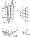
- FIG. 1 there is shown a blade 10 of a distributor of a turbine of a turbomachine.
- the blade 10 is provided with a cavity 12 and an inner wall 14 surrounding the cavity 12.
- the blade 10 has a first end 16 and a second end 18, which, in the example illustrated in FIG. figure 1 , are its radially outer and radially inner ends. Both ends 16, 18 are open and communicate with the cavity 12 of the blade 10.
- the blade 10 has a leading edge 20 and a trailing edge 22.
- a liner 26 which is in the form of a preformed and welded sheet having a substantially conical shape.
- the ends of the liner rest on the inner wall 14.
- the body of the liner 26, located between the ends thereof, is not in contact with the inner wall 14.
- the jacket 26 is provided with emission holes 28, which are made by drilling through the thickness of the jacket 26. These emission holes 28 are characterized by a diameter d.
- the blade 10 also comprises bridges 30 which pass through the cavity 14 in a transverse direction thereof and through orifices 32 arranged towards its trailing edge 22.
- the bridges 30 and the through orifices 32 play no role in the of the present invention.
- the arrow 100 represents a flow of cooling air introduced into the jacket 26 disposed in the cavity 12 by the first end 16, and the arrow 200 represents a part of this cooling air flow which escapes from the jacket 26 through the second end 18.
- This air flow through the jacket 26 can supply cooling air other parts of the engine.
- the cooling air is evacuated through the emission holes 28 in the form of air jets which are projected onto the inner wall 14 at impact points 50 thereof.
- the cooling fins 24 and the emission holes 28 are arranged, respectively on the inner wall 14 of the blade 10 and on the jacket 26 arranged in the blade 10, so that the impact points 50 of the cooling air jets are located between the cooling fins 24, as shown in FIG. show it figure 3 .
- the cooling air jets do not arrive on cooling fins 24, but between cooling fins 24.
- the most disadvantageous operating conditions from a thermomechanical point of view of the turbomachine, and in particular its critical operating point are well known to the skilled person. They correspond to high temperatures between 700 ° C and 1100 ° C, for which the mechanical properties of materials are impaired. It is in these most penalizing operating conditions that the cooling of the blade 10 must be the most effective.
- the Dawn is made of superalloy.
- the jacket is made of heat-resistant alloy.
- the numerical simulation is carried out on a software of C.A.O. (Computer Aided Design) having a temperature conditioning module.
- C.A.O. Computer Aided Design
- the above example was realized with the Scale Factor module of C.A.O. Catia.
Landscapes
- Engineering & Computer Science (AREA)
- Mechanical Engineering (AREA)
- General Engineering & Computer Science (AREA)
- Physics & Mathematics (AREA)
- Fluid Mechanics (AREA)
- Turbine Rotor Nozzle Sealing (AREA)
Claims (7)
- Anordnung zur Kühlung einer Schaufel (10) eines Leitrades einer Turbomaschine,
wobei die Schaufel (10) mit wenigstens einem Hohlraum (12) ausgestattet ist, der von einer Innenwandung (14) umgeben ist, welche Kühlrippen (24) aufweist, die um einen Abstand (p) voneinander beabstandet sind und jeweils eine Dicke (e) aufweisen,
wobei die Schaufel (10) mit einem Mantel (26) ausgestattet und von Ausströmungslöchern (28) durchquert ist, die jeweils einen Durchmesser aufweisen, und jedes Ausströmungsloch (28) des Mantels (26), wenn der Mantel (26) in dem Hohlraum (12) der Schaufel (10) angeordnet ist, sowie für den kritischen Betriebspunkt der Turbomaschine, sich gegenüber einer Stelle der Innenwandung (14) der Schaufel (10), die zwischen Kühlrippen (24) gelegen ist, befindet, und dass wenn der Mantel (26) in dem Hohlraum (12) der Schaufel (10) angeordnet ist, sowie für den kritischen Betriebspunkt der Turbomaschine, der Abstand (p) und die Dicke (e) der Kühlrippen (24) die Beziehung erfüllen:
- Kühlungsanordnung nach Anspruch 1, dadurch gekennzeichnet, dass wenn der Mantel (26) in dem Hohlraum (12) der Schaufel (10) angeordnet ist, sowie für den kritischen Betriebspunkt der Turbomaschine, wenigstens eine Stelle der Innenwandung (14) der Schaufel (10), welche zwischen Kühlrippen (24) gelegen ist, sich gegenüber wenigstens einem Ausströmungsloch (28) des Mantels (26) befindet.
- Kühlungsanordnung nach einem der Ansprüche 1 bis 2, dadurch gekennzeichnet, dass für den kritischen Betriebspunkt der Turbomaschine keine Kühlrippe (24) der Innenwandung (14) der Schaufel (10) sich gegenüber einem Ausströmungsloch (28) des Mantels (26) befindet.
- Schaufel (10) einer Turbine einer Turbomaschine, dadurch gekennzeichnet, dass sie eine Kühlungsanordnung nach Anspruch 1 bis 3 umfasst.
- Turbine einer Turbomaschine, dadurch gekennzeichnet, dass sie wenigstens eine Schaufel (10) nach Anspruch 4 umfasst.
- Luftfahrzeugtriebwerk, dadurch gekennzeichnet, dass es wenigstens eine Schaufel (10) nach Anspruch 4 umfasst.
- Luftfahrzeugtriebwerk, dadurch gekennzeichnet, dass es eine Vorrichtung zur Entnahme von Kühlluft umfasst, die Kühlluft bis zum Inneren eines Mantels (26), welcher in einem Hohlraum (12) wenigstens einer Schaufel (10) nach Anspruch 4 angeordnet ist, führt, wobei die Kühlluft anschließend auf die Innenwandung (14) der Schaufel (10) durch in dem Mantel (26) ausgebildete Ausströmungslöcher (28) in Form einer Kühlungsströmung ausgestoßen wird, die eine Reynolds-Zahl (Re) aufweist, welche als charakteristische Länge den Durchmesser (d) der Ausströmungslöcher (28) hat und die Beziehung erfüllt:

Applications Claiming Priority (1)
| Application Number | Priority Date | Filing Date | Title |
|---|---|---|---|
| FR0553357A FR2893080B1 (fr) | 2005-11-07 | 2005-11-07 | Agencement de refroidissement d'une aube d'une turbine, aube de turbine le comportant, turbine et moteur d'aeronef en etant equipes |
Publications (2)
| Publication Number | Publication Date |
|---|---|
| EP1783326A1 EP1783326A1 (de) | 2007-05-09 |
| EP1783326B1 true EP1783326B1 (de) | 2017-06-07 |
Family
ID=36809548
Family Applications (1)
| Application Number | Title | Priority Date | Filing Date |
|---|---|---|---|
| EP06123454.8A Active EP1783326B1 (de) | 2005-11-07 | 2006-11-03 | Kühlungsanordnung in einer Turbinenschaufel, Turbinenschaufel, Turbine und Flugantrieb damit ausgestattet |
Country Status (6)
| Country | Link |
|---|---|
| US (1) | US7658591B2 (de) |
| EP (1) | EP1783326B1 (de) |
| JP (1) | JP2007132347A (de) |
| CA (1) | CA2567126C (de) |
| FR (1) | FR2893080B1 (de) |
| RU (1) | RU2425983C2 (de) |
Families Citing this family (16)
| Publication number | Priority date | Publication date | Assignee | Title |
|---|---|---|---|---|
| FR2922597B1 (fr) * | 2007-10-19 | 2012-11-16 | Snecma | Aube refroidie de turbomachine |
| FR2970666B1 (fr) | 2011-01-24 | 2013-01-18 | Snecma | Procede de perforation d'au moins une paroi d'une chambre de combustion |
| US8628294B1 (en) * | 2011-05-19 | 2014-01-14 | Florida Turbine Technologies, Inc. | Turbine stator vane with purge air channel |
| JP5791405B2 (ja) * | 2011-07-12 | 2015-10-07 | 三菱重工業株式会社 | 回転機械の翼体 |
| DE102012209549A1 (de) * | 2012-06-06 | 2013-12-12 | Siemens Aktiengesellschaft | Kühlmittelüberbrückungsleitung für eine Gasturbine |
| US9169733B2 (en) * | 2013-03-20 | 2015-10-27 | General Electric Company | Turbine airfoil assembly |
| CN106255806B (zh) * | 2014-05-08 | 2019-05-31 | 西门子股份公司 | 涡轮组件和相应的操作方法 |
| US10024172B2 (en) * | 2015-02-27 | 2018-07-17 | United Technologies Corporation | Gas turbine engine airfoil |
| US10711702B2 (en) * | 2015-08-18 | 2020-07-14 | General Electric Company | Mixed flow turbocore |
| PL232314B1 (pl) | 2016-05-06 | 2019-06-28 | Gen Electric | Maszyna przepływowa zawierająca system regulacji luzu |
| US10309246B2 (en) | 2016-06-07 | 2019-06-04 | General Electric Company | Passive clearance control system for gas turbomachine |
| US10605093B2 (en) | 2016-07-12 | 2020-03-31 | General Electric Company | Heat transfer device and related turbine airfoil |
| US10392944B2 (en) * | 2016-07-12 | 2019-08-27 | General Electric Company | Turbomachine component having impingement heat transfer feature, related turbomachine and storage medium |
| EP3421722A1 (de) * | 2017-06-29 | 2019-01-02 | Siemens Aktiengesellschaft | Turbinenanordnung zur prallkühlung und verfahren zur montage |
| US10746283B2 (en) * | 2017-08-21 | 2020-08-18 | Raytheon Technologies Corporation | Damped fluid transfer tube for a gas turbine engine |
| FR3079551B1 (fr) | 2018-03-29 | 2020-04-24 | Safran Helicopter Engines | Aube de distributeur de turbine comportant une paroi interne de refroidissement issue de fabrication additive |
Family Cites Families (16)
| Publication number | Priority date | Publication date | Assignee | Title |
|---|---|---|---|---|
| SU1238465A2 (ru) * | 1983-08-05 | 1996-02-27 | Уфимский авиационный институт им.Серго Орджоникидзе | Охлаждаемая лопатка турбины |
| US5232343A (en) * | 1984-05-24 | 1993-08-03 | General Electric Company | Turbine blade |
| JPS6163401A (ja) * | 1984-09-04 | 1986-04-01 | ハマシウセイ株式会社 | 集成材 |
| JP3142850B2 (ja) * | 1989-03-13 | 2001-03-07 | 株式会社東芝 | タービンの冷却翼および複合発電プラント |
| JPH0663442B2 (ja) * | 1989-09-04 | 1994-08-22 | 株式会社日立製作所 | タービン翼 |
| US5259730A (en) * | 1991-11-04 | 1993-11-09 | General Electric Company | Impingement cooled airfoil with bonding foil insert |
| EP0541207A1 (de) * | 1991-11-04 | 1993-05-12 | General Electric Company | Prallgekühltes Schaufelblatt mit einem die Blatthälften verbundendem Einsatz |
| US5695321A (en) * | 1991-12-17 | 1997-12-09 | General Electric Company | Turbine blade having variable configuration turbulators |
| US5413463A (en) * | 1991-12-30 | 1995-05-09 | General Electric Company | Turbulated cooling passages in gas turbine buckets |
| JP3110227B2 (ja) * | 1993-11-22 | 2000-11-20 | 株式会社東芝 | タービン冷却翼 |
| JPH07233702A (ja) * | 1994-02-23 | 1995-09-05 | Mitsubishi Heavy Ind Ltd | ガスタービン中空動翼 |
| JPH08338203A (ja) * | 1995-06-09 | 1996-12-24 | Hitachi Ltd | ガスタービン静翼 |
| EP0905353B1 (de) * | 1997-09-30 | 2003-01-15 | ALSTOM (Switzerland) Ltd | Prallanordnung für ein konvektives Kühl- oder Heizverfahren |
| EP1191189A1 (de) * | 2000-09-26 | 2002-03-27 | Siemens Aktiengesellschaft | Gasturbinenschaufel |
| EP1283326B1 (de) * | 2001-08-09 | 2005-12-21 | Siemens Aktiengesellschaft | Kühlung einer Turbinenschaufel |
| US6997675B2 (en) * | 2004-02-09 | 2006-02-14 | United Technologies Corporation | Turbulated hole configurations for turbine blades |
-
2005
- 2005-11-07 FR FR0553357A patent/FR2893080B1/fr not_active Expired - Lifetime
-
2006
- 2006-11-03 RU RU2006139012/06A patent/RU2425983C2/ru active
- 2006-11-03 CA CA2567126A patent/CA2567126C/fr active Active
- 2006-11-03 EP EP06123454.8A patent/EP1783326B1/de active Active
- 2006-11-06 US US11/556,867 patent/US7658591B2/en active Active
- 2006-11-06 JP JP2006299893A patent/JP2007132347A/ja active Pending
Also Published As
| Publication number | Publication date |
|---|---|
| US7658591B2 (en) | 2010-02-09 |
| RU2425983C2 (ru) | 2011-08-10 |
| US20070122281A1 (en) | 2007-05-31 |
| FR2893080A1 (fr) | 2007-05-11 |
| RU2006139012A (ru) | 2008-05-10 |
| CA2567126C (fr) | 2013-09-03 |
| JP2007132347A (ja) | 2007-05-31 |
| CA2567126A1 (fr) | 2007-05-07 |
| FR2893080B1 (fr) | 2012-12-28 |
| EP1783326A1 (de) | 2007-05-09 |
Similar Documents
| Publication | Publication Date | Title |
|---|---|---|
| EP1783326B1 (de) | Kühlungsanordnung in einer Turbinenschaufel, Turbinenschaufel, Turbine und Flugantrieb damit ausgestattet | |
| EP1840331B1 (de) | Turbomachinendüse | |
| CA2510669C (fr) | Aube fixe de turbine a refroidissement ameliore | |
| FR2712919A1 (fr) | Aube refroidie de turbine. | |
| FR2967456A1 (fr) | Turbomachine avec des aubes fixes refroidies | |
| EP2917518B1 (de) | Aufnahme eines entlüftungsrohr einer turbomachine | |
| EP3551859B1 (de) | Vorrichtung zur abwärmerückgewinnung mit verbesserter abdichtung | |
| FR3080406A1 (fr) | Distributeur de turbine ameliore pour turbomachine | |
| WO2023099533A1 (fr) | Turbomachine axiale triple-flux avec échangeur de chaleur divergeant dans le troisième flux | |
| CA2478954C (fr) | Aube refroidie de moteur a turbine a gaz | |
| CA2641438C (fr) | Aube refroidie de turbomachine | |
| EP3638886B1 (de) | Kühlungsanordnung für ein ringformiges aussengehäuse einer turbine | |
| EP3942158B1 (de) | Mit optimiertem kühlkreislauf ausgestattete turbinentriebwerksschaufel | |
| EP1452695A1 (de) | Mit verringertem Kühlluftdurchstrom gekühlte Turbinenschaufel | |
| FR2943380A1 (fr) | Aube de distributeur comprenant au moins une fente | |
| EP4441349B1 (de) | Luft-öl-wärmetauscher | |
| EP4441351B1 (de) | Luft-öl-wärmetauscher mit einem bypass für eine turbomaschine | |
| BE1030017B1 (fr) | Échangeur de chaleur air-huile avec by-pass pour turbomachine | |
| FR3079848A1 (fr) | Procede de depot d'un materiau anti-usure sur un element aubage pour une turbomachine d'aeronef | |
| FR3068732A1 (fr) | Dispositif de refroidissement | |
| WO2020193912A1 (fr) | Aube de turbomachine equipee d'un circuit de refroidissement et procede de fabrication a cire perdue d'une telle aube | |
| FR3070058A1 (fr) | Turbomachine pour aeronef comprenant un element de refroidissement ameliorant le refroidissement par convection et offrant un refroidissement par impact de jet d'air d'une bride de liaison terminale de paroi de chambre annulaire de combustion | |
| BE406008A (de) | ||
| FR3063031A1 (fr) | Dispositif de support d'une piece metallique en vue de son soudage ou brasage |
Legal Events
| Date | Code | Title | Description |
|---|---|---|---|
| PUAI | Public reference made under article 153(3) epc to a published international application that has entered the european phase |
Free format text: ORIGINAL CODE: 0009012 |
|
| AK | Designated contracting states |
Kind code of ref document: A1 Designated state(s): AT BE BG CH CY CZ DE DK EE ES FI FR GB GR HU IE IS IT LI LT LU LV MC NL PL PT RO SE SI SK TR |
|
| AX | Request for extension of the european patent |
Extension state: AL BA HR MK YU |
|
| 17P | Request for examination filed |
Effective date: 20071011 |
|
| AKX | Designation fees paid |
Designated state(s): DE FR GB |
|
| 17Q | First examination report despatched |
Effective date: 20091027 |
|
| REG | Reference to a national code |
Ref country code: DE Ref legal event code: R079 Ref document number: 602006052723 Country of ref document: DE Free format text: PREVIOUS MAIN CLASS: F01D0005180000 Ipc: F01D0009040000 |
|
| GRAP | Despatch of communication of intention to grant a patent |
Free format text: ORIGINAL CODE: EPIDOSNIGR1 |
|
| STAA | Information on the status of an ep patent application or granted ep patent |
Free format text: STATUS: GRANT OF PATENT IS INTENDED |
|
| RIC1 | Information provided on ipc code assigned before grant |
Ipc: F01D 5/18 20060101ALI20161201BHEP Ipc: F01D 9/04 20060101AFI20161201BHEP Ipc: F01D 9/06 20060101ALI20161201BHEP |
|
| INTG | Intention to grant announced |
Effective date: 20170103 |
|
| GRAS | Grant fee paid |
Free format text: ORIGINAL CODE: EPIDOSNIGR3 |
|
| GRAA | (expected) grant |
Free format text: ORIGINAL CODE: 0009210 |
|
| STAA | Information on the status of an ep patent application or granted ep patent |
Free format text: STATUS: THE PATENT HAS BEEN GRANTED |
|
| AK | Designated contracting states |
Kind code of ref document: B1 Designated state(s): DE FR GB |
|
| REG | Reference to a national code |
Ref country code: GB Ref legal event code: FG4D Free format text: NOT ENGLISH |
|
| GRAA | (expected) grant |
Free format text: ORIGINAL CODE: 0009210 |
|
| REG | Reference to a national code |
Ref country code: DE Ref legal event code: R096 Ref document number: 602006052723 Country of ref document: DE |
|
| REG | Reference to a national code |
Ref country code: FR Ref legal event code: PLFP Year of fee payment: 12 |
|
| REG | Reference to a national code |
Ref country code: DE Ref legal event code: R097 Ref document number: 602006052723 Country of ref document: DE |
|
| PLBE | No opposition filed within time limit |
Free format text: ORIGINAL CODE: 0009261 |
|
| STAA | Information on the status of an ep patent application or granted ep patent |
Free format text: STATUS: NO OPPOSITION FILED WITHIN TIME LIMIT |
|
| 26N | No opposition filed |
Effective date: 20180308 |
|
| REG | Reference to a national code |
Ref country code: FR Ref legal event code: PLFP Year of fee payment: 13 |
|
| PGFP | Annual fee paid to national office [announced via postgrant information from national office to epo] |
Ref country code: DE Payment date: 20251118 Year of fee payment: 20 |
|
| PGFP | Annual fee paid to national office [announced via postgrant information from national office to epo] |
Ref country code: GB Payment date: 20251125 Year of fee payment: 20 |
|
| PGFP | Annual fee paid to national office [announced via postgrant information from national office to epo] |
Ref country code: FR Payment date: 20251125 Year of fee payment: 20 |