EP1783331A1 - Système comprenant un arbre à cames d'admission, un arbre à cames d'échappement et un variateur de phase, et utilisation de ce système - Google Patents
Système comprenant un arbre à cames d'admission, un arbre à cames d'échappement et un variateur de phase, et utilisation de ce système Download PDFInfo
- Publication number
- EP1783331A1 EP1783331A1 EP05110407A EP05110407A EP1783331A1 EP 1783331 A1 EP1783331 A1 EP 1783331A1 EP 05110407 A EP05110407 A EP 05110407A EP 05110407 A EP05110407 A EP 05110407A EP 1783331 A1 EP1783331 A1 EP 1783331A1
- Authority
- EP
- European Patent Office
- Prior art keywords
- camshaft
- gear
- adjuster
- intake
- fastening means
- Prior art date
- Legal status (The legal status is an assumption and is not a legal conclusion. Google has not performed a legal analysis and makes no representation as to the accuracy of the status listed.)
- Granted
Links
Images


Classifications
-
- F—MECHANICAL ENGINEERING; LIGHTING; HEATING; WEAPONS; BLASTING
- F01—MACHINES OR ENGINES IN GENERAL; ENGINE PLANTS IN GENERAL; STEAM ENGINES
- F01L—CYCLICALLY OPERATING VALVES FOR MACHINES OR ENGINES
- F01L1/00—Valve-gear or valve arrangements, e.g. lift-valve gear
- F01L1/34—Valve-gear or valve arrangements, e.g. lift-valve gear characterised by the provision of means for changing the timing of the valves without changing the duration of opening and without affecting the magnitude of the valve lift
- F01L1/344—Valve-gear or valve arrangements, e.g. lift-valve gear characterised by the provision of means for changing the timing of the valves without changing the duration of opening and without affecting the magnitude of the valve lift changing the angular relationship between crankshaft and camshaft, e.g. using helicoidal gear
- F01L1/3442—Valve-gear or valve arrangements, e.g. lift-valve gear characterised by the provision of means for changing the timing of the valves without changing the duration of opening and without affecting the magnitude of the valve lift changing the angular relationship between crankshaft and camshaft, e.g. using helicoidal gear using hydraulic chambers with variable volume to transmit the rotating force
-
- F—MECHANICAL ENGINEERING; LIGHTING; HEATING; WEAPONS; BLASTING
- F01—MACHINES OR ENGINES IN GENERAL; ENGINE PLANTS IN GENERAL; STEAM ENGINES
- F01L—CYCLICALLY OPERATING VALVES FOR MACHINES OR ENGINES
- F01L1/00—Valve-gear or valve arrangements, e.g. lift-valve gear
- F01L1/02—Valve drive
-
- F—MECHANICAL ENGINEERING; LIGHTING; HEATING; WEAPONS; BLASTING
- F01—MACHINES OR ENGINES IN GENERAL; ENGINE PLANTS IN GENERAL; STEAM ENGINES
- F01L—CYCLICALLY OPERATING VALVES FOR MACHINES OR ENGINES
- F01L1/00—Valve-gear or valve arrangements, e.g. lift-valve gear
- F01L1/02—Valve drive
- F01L1/022—Chain drive
-
- F—MECHANICAL ENGINEERING; LIGHTING; HEATING; WEAPONS; BLASTING
- F01—MACHINES OR ENGINES IN GENERAL; ENGINE PLANTS IN GENERAL; STEAM ENGINES
- F01L—CYCLICALLY OPERATING VALVES FOR MACHINES OR ENGINES
- F01L1/00—Valve-gear or valve arrangements, e.g. lift-valve gear
- F01L1/02—Valve drive
- F01L1/024—Belt drive
-
- F—MECHANICAL ENGINEERING; LIGHTING; HEATING; WEAPONS; BLASTING
- F01—MACHINES OR ENGINES IN GENERAL; ENGINE PLANTS IN GENERAL; STEAM ENGINES
- F01L—CYCLICALLY OPERATING VALVES FOR MACHINES OR ENGINES
- F01L1/00—Valve-gear or valve arrangements, e.g. lift-valve gear
- F01L1/34—Valve-gear or valve arrangements, e.g. lift-valve gear characterised by the provision of means for changing the timing of the valves without changing the duration of opening and without affecting the magnitude of the valve lift
- F01L1/344—Valve-gear or valve arrangements, e.g. lift-valve gear characterised by the provision of means for changing the timing of the valves without changing the duration of opening and without affecting the magnitude of the valve lift changing the angular relationship between crankshaft and camshaft, e.g. using helicoidal gear
-
- F—MECHANICAL ENGINEERING; LIGHTING; HEATING; WEAPONS; BLASTING
- F01—MACHINES OR ENGINES IN GENERAL; ENGINE PLANTS IN GENERAL; STEAM ENGINES
- F01L—CYCLICALLY OPERATING VALVES FOR MACHINES OR ENGINES
- F01L1/00—Valve-gear or valve arrangements, e.g. lift-valve gear
- F01L1/02—Valve drive
- F01L1/04—Valve drive by means of cams, camshafts, cam discs, eccentrics or the like
- F01L1/047—Camshafts
- F01L1/053—Camshafts overhead type
- F01L2001/0537—Double overhead camshafts [DOHC]
-
- F—MECHANICAL ENGINEERING; LIGHTING; HEATING; WEAPONS; BLASTING
- F01—MACHINES OR ENGINES IN GENERAL; ENGINE PLANTS IN GENERAL; STEAM ENGINES
- F01L—CYCLICALLY OPERATING VALVES FOR MACHINES OR ENGINES
- F01L1/00—Valve-gear or valve arrangements, e.g. lift-valve gear
- F01L1/34—Valve-gear or valve arrangements, e.g. lift-valve gear characterised by the provision of means for changing the timing of the valves without changing the duration of opening and without affecting the magnitude of the valve lift
- F01L1/344—Valve-gear or valve arrangements, e.g. lift-valve gear characterised by the provision of means for changing the timing of the valves without changing the duration of opening and without affecting the magnitude of the valve lift changing the angular relationship between crankshaft and camshaft, e.g. using helicoidal gear
- F01L1/3442—Valve-gear or valve arrangements, e.g. lift-valve gear characterised by the provision of means for changing the timing of the valves without changing the duration of opening and without affecting the magnitude of the valve lift changing the angular relationship between crankshaft and camshaft, e.g. using helicoidal gear using hydraulic chambers with variable volume to transmit the rotating force
- F01L2001/3445—Details relating to the hydraulic means for changing the angular relationship
- F01L2001/34483—Phaser return springs
Definitions
- the invention relates to the use of such a system in an internal combustion engine having at least one cylinder.
- Timing is a solution to reduce fuel consumption and thus reduce emissions of pollutants or to increase performance.
- the problem is the fuel consumption and thus the efficiency, especially in gasoline engines.
- the reason for this lies in the basic working method of the gasoline engine.
- the gasoline engine works with a homogeneous fuel-air mixture, which - if no Direct injection is present - is prepared by external mixture formation by fuel is introduced into the intake air in the intake tract.
- the desired power is adjusted by changing the filling of the combustion chamber, so that the operating method of the gasoline engine - unlike the diesel engine - is based on a quantity control.
- the load control is usually carried out by means of a throttle valve provided in the intake tract.
- a throttle valve provided in the intake tract.
- the pressure of the intake air behind the throttle valve can be reduced more or less.
- the air mass i. E. the quantity will be set.
- the quantity control by means of throttle valve has thermodynamic disadvantages due to the pressure reduction and the associated throttle losses.
- variable valvetrain In contrast to conventional valve trains, where both the stroke of the valves and the timing, d. H. the opening and closing times of the intake and exhaust valves, due to the non-flexible, since non-adjustable mechanism of the valve train are given as immutable variables, these parameters can be varied more or less by means of variable valve trains influencing the combustion process and thus the fuel consumption.
- the variation of the timing can further - as mentioned above - be used to increase the performance.
- the ideal solution would be a fully variable valve control, which allows for specially tuned values for the stroke and the timing for any operating point of the gasoline engine.
- the quantity of the intake mixture and thus the load can be controlled by closing the intake valve, wherein the sucked mixture is sucked in at ambient pressure due to the missing throttle even when changing the charge in the partial load range.
- One way to vary the timing of the valves is to use a camshaft phaser with which the camshaft is rotated a certain angle relative to the crankshaft so that the timing is shifted early or late.
- a camshaft adjuster regardless of the operating principle that underlies them.
- Such adjusting devices are usually hydraulically actuated or controlled, wherein one or more pressure chambers are selectively acted upon with hydraulic oil or relieved.
- the Indian DE 198 50 947 A1 described camshaft adjuster is equipped with an axially displaceable piston device, wherein an axial displacement of the piston means a rotation of the camshaft relative to a camshaft driving pulley implies and thus a rotation of the camshaft relative to the crankshaft, which is coupled in its rotational movement via a belt with the pulley.
- adjusting device described is merely an example of a camshaft adjuster, which is formed by means of an axially displaceable piston device.
- a vane pump 100 has an outer rotor 102 and an inner rotor 104 and is shown by way of example and schematically in FIG.
- the outer rotor 102 is connected in a rotationally fixed manner to the outer toothed belt wheel 101, whereas the inner rotor 104 is fixed to the camshaft 103.
- the inner rotor 104 is rotated relative to the outer rotor 102, which is realized by introducing a fluid into a plurality of pressure chambers 105.
- the pressure chambers 105 are formed by the vanes 102a, 104a of the rotors 102, 104 and the rotors 102, 104 themselves and are sealed from the environment by means of sealing strips arranged at the ends of the vanes 102a, 104a.
- the rotational angle positions of the camshafts and the crankshaft are set and synchronized, inter alia, in a special manufacturing station.
- the crankshaft is rotated until it abuts against a predetermined positioning pin, wherein the camshafts can be positioned and synchronized by being rotated by means provided at their free shaft ends notches in the corresponding rotational angular position.
- An engagement of a tool in the arranged on the camshaft gears optionally with subsequent rotation of the corresponding camshaft ensures the synchronization of the gears.
- the synchronization of the two camshaft adjuster complete with gears usually with a positioning tool that engages in position marks, which are provided on the two camshaft adjusters in such a way that the positioning tool only in a single presettable arrangement of the two camshaft adjuster can engage relative to each other in the position marks.
- the gears or the camshaft adjuster are fixed by means of screws, wherein for fastening a gear or a camshaft adjuster to the camshaft usually a screw is screwed in the direction of the longitudinal axis of the camshaft. In this case, a screw is screwed into the intake camshaft and a screw in the exhaust camshaft as part of the assembly.
- both camshafts are equipped with a camshaft adjuster or both camshafts do not have such a camshaft adjuster
- the tools of the manufacturing station for screwing the screws on the same engagement depth are provided.
- Embodiments of the system in which the first fastening means and the second fastening means are each formed by a screw are advantageous.
- the use of screws for attachment of the gear or the camshaft adjuster allows the application of the system according to the invention when using conventional production lines and manufacturing stations, which are used in the prior art screws as fasteners.
- the tools of the manufacturing station for screwing the screws in the two camshafts on an equal penetration depth Due to the erfmdungsconcee training of the second gear i. of the gear wheel, which is arranged on the non-adjustable in the timing second camshaft, the tools of the manufacturing station for screwing the screws in the two camshafts on an equal penetration depth.
- This is achieved by a constructive measure in which the second gear - in contrast to a conventional gear - dimensioned in its axial dimension in the way that in the assembled state, the screws - seen in the direction of the camshaft longitudinal axes - arranged substantially at the same height ie the screw heads lie on a common virtual plane, which is perpendicular to the longitudinal axis of the camshaft.
- the second gear according to the invention compensates by its comparatively large axial extent the space, which is claimed by the additional arrangement of a camshaft adjuster on the camshaft.
- an internal combustion engine which has the erfmdungsdorfe system, i. an internal combustion engine in which only the intake camshaft or only the exhaust camshaft is equipped with a camshaft adjuster, fed to a conventional manufacturing station, which is originally designed for the assembly of internal combustion engines, in which both camshafts are equipped with a camshaft adjuster, the second gear without Modification must be made at the manufacturing station, ie assembled be fastened.
- the assembly process for fastening the second gear corresponds to the assembly process of a camshaft adjuster.
- the tools work in both cases with the same depth of penetration.
- the object underlying the invention is achieved, namely to show a solution with which the production or assembly of an internal combustion engine, in which only the intake camshaft or only the exhaust camshaft is equipped with a camshaft adjuster, using a conventional production line or conventional manufacturing station allows becomes.
- the control time to which the intake valve closes affects the filling of the combustion chamber and thus also the torque characteristic of the internal combustion engine.
- Variable timing on the intake side also allow the variation of the so-called valve overlap, ie the crank angle range, in which the exhaust valve is not yet closed when the intake valve is open.
- valve overlap ie the crank angle range
- flushing losses may occur, with part of the sucked mixture flowing through the combustion chamber without participating in the combustion. This leads on the one hand to poorer efficiencies, but on the other hand to a larger cylinder filling and thus to a higher performance.
- a variable closing time of the Inlet valve allows the variation of the valve overlap in relation to the speed.
- camshaft adjuster is designed as a die gelzellennockenwellenphasenversteller.
- the system according to the invention can be used both in internal combustion engines, in which a vane pump serves as a camshaft adjuster, but also, if a camshaft adjuster is used, whose operating principle is based on an axially displaceable piston device. In both cases, it is necessary to solve the assembly problems discussed above in terms of penetration depth of the assembly tools, wherein the inventive design of the second gear wheel, regardless of the type of camshaft adjuster used proves to be expedient.
- the second gear is modularly constructed from at least two components.
- the modular design has advantages because the second gear has to perform several different functions and in this way the at least two components can be formed according to their respective function.
- the gear must receive gear teeth which are engaged with a drive chain or drive belt, respectively, to be rotated by a rotating crankshaft.
- the second gear must span a predetermined axial path along the longitudinal axis of the camshaft of the second camshaft or bridge to solve the problem underlying the invention, ie to ensure that seen in the assembled state, the first attachment means and the second attachment means in the direction of the camshaft longitudinal axes are arranged substantially at the same height ie to come to rest on a common virtual plane perpendicular to the camshaft longitudinal axes.
- embodiments of the system are advantageous in which the second gear has at one end a gear main body for receiving the teeth and having a spacer through the axial length of the axial position of the second fastening means in the assembled state is adjustable.
- the gear main body opposite end has a disc-shaped body, wherein a spacer between the gear main body and the disc-shaped body is provided by the axial length of the axial position of the second fastening means in the assembled state is adjustable.
- embodiments of the system are advantageous in which the camshaft adjuster and the disc-shaped body each have position marks which are arranged in such a way that the first gear and the second gear are connectable only in a vorgebaren arrangement relative to each other by means of a positioning tool, wherein the connection can be realized in that the positioning tool engages in the position marks.
- the position marks can be formed, for example, in the form of recesses or in the form of projecting pins.
- the individual components can in principle be releasably connected to each other, for example by a screw connection, a shrink fit with press fit or a click connection.
- the second gear is also possible to form the second gear as a monolithic component, for example as a casting or forging.
- Embodiments of the system in which a bush is provided between the second gearwheel and the second camshaft are advantageous. The reasons are the following.
- the arrangement of a bush between the second gear and the second camshaft is adapted to compensate for this difference in diameter.
- the bushing can be connected inseparably or detachably to the second gearwheel or can be formed in one piece with this gearwheel.
- Embodiments of the system in which a seal is provided between the bushing and the second camshaft are advantageous.
- a seal is required so that the oil introduced into the system for lubrication of the camshaft does not leak out at the camshaft and second gear joint, resulting in contamination of the surrounding components and the environment.
- the gear itself is usually not a barrier to the escaping oil, because the gear is preferably made of sintered metal, which is porous and thus oil-permeable.
- Systems of a type described above can be used in an internal combustion engine with at least one cylinder, and are then characterized in that control means of the internal combustion engine are operated by means of the at least one intake camshaft and the at least one exhaust camshaft, with which controlled the change in charge of the at least one cylinder of the internal combustion engine wherein the phaser is used to at least partially vary the timing of the charge cycle.
- FIG. 1 has already been explained in connection with the description of the prior art.
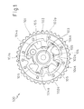
- Figure 2 shows a first embodiment of the system 1.
- the - not shown longitudinal axes - the camshafts are perpendicular to the plane of the drawing.
- the system 1 has an intake camshaft and an exhaust camshaft, both camshafts not being visible in the side view shown in FIG.
- a first gear 4 and a camshaft adjuster 6 are provided, whereas at the end of the exhaust camshaft only one gear 5, which may be referred to as the second gear 5, is arranged.
- Both gears 4, 5 are formed as toothed belt wheels, arranged on the same side of the system 1 and by means of a belt - not shown - of a revolving crankshaft - also not shown - set in rotation. This so-called belt drive is protected by a cover 15, which is arranged above the two gears 4, 5.
- the camshaft adjuster 6 is fixed together with the first gear 4 by means of a first fastening means 7 at the end of the intake camshaft.
- the second gear 5 is fixed by means of a second fastening means 8 at the end of the exhaust camshaft.
- fastening means 7, 9 serve screws 8, 10th
- the second gear 5 is modular and has, inter alia, a gear main body 5a for receiving the teeth, which are in operation of the internal combustion engine with a belt engaged and thus provide the drive of the valve train. Furthermore, the second gear 5 has a disk-shaped body 5b.
- the structure of the second gear 5 is shown in Figure 4 and will be described in more detail below. In this connection, the spacer which is provided between the gear main body 5a and the disk-shaped body 5b is also described in detail.
- the phaser 6 is formed as a vane-type camshaft phaser 6a.
- the structure of the camshaft adjuster 6 can be seen in FIG. 3 and will be explained in more detail in connection with the description of FIG.
- the housing 19 of the camshaft adjuster 6 and the disc-shaped body 5b of the second gear 5 each have four position marks 11a, 11b in the form of semicircular recesses 12a, 12b, which are arranged on the outer circumference of the housing 19 and the disc-shaped body 5b.
- the position marks 11a, 11b are irregular d. H. distributed at different distances from each other on the corresponding circumference and in such a way that the two gears 4, 5 are interconnected only in a vorgebaren arrangement relative to each other by means of a positioning tool which engages in the position marks 11 a, 11 b.
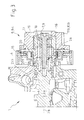
- FIG. 3 shows a section along the line A - A marked in FIG.
- the camshaft adjuster 6 which is arranged at the end 2a of the intake camshaft 2, will be discussed.
- the camshaft adjuster 6 of the embodiment shown in Figure 3 operates on the principle of a vane pump 6a and has an outer rotor 17 and an inner rotor 16.
- the inner rotor 16 is in the assembled state of the system 1 d. H. when the screw 9 is tightened firmly with the first camshaft 2c i. clamped with the intake camshaft 2.
- the inner rotor 16 rotates in the operation of the internal combustion engine with the intake camshaft 2 about the camshaft longitudinal axis 2b.
- the outer rotor 17 is formed integrally with the housing 19 of the camshaft adjuster 6, so that the outer rotor is rotatably connected in the assembled state with the first toothed belt 4.
- Both rotors 16, 17 are connected to each other via a coil spring 20 to prevent any rotation of the two rotors 16, 17 against each other and to provide a predetermined restoring force.
- the inner rotor 16 is rotated relative to the outer rotor 17, which is realized by introducing hydraulic oil into a plurality of pressure chambers - not visible.
- oil supply holes 21b are provided which pass through the intake camshaft 2 and open at the end 2a of the camshaft 2 in the pressure chambers of the camshaft adjuster 6, so that the pressure chambers can be supplied with oil.
- the - not visible in the section shown in Figure 3 - pressure chambers are formed between the wings of the two rotors 16, 17 and sealed with sealing strips 18.
- the inner rotor 16 is rotated relative to the outer rotor 17 or the camshaft 2 rotatably connected to the inner rotor 16 relative to the first gear 4 and thus adjusted relative to the crankshaft.
- FIG. 4 shows a section along the line B-B marked in FIG. 2.
- the structure and mode of operation of the second gearwheel 5, which is arranged at the end 3a of the exhaust camshaft 3, will be discussed below.
- the second gear 5 is in the assembled state of the system 1 d. H. with tightened screw 10 fixed to the second camshaft 3c d. H. clamped or connected to the exhaust camshaft 3 and rotates during operation of the internal combustion engine with the exhaust camshaft 3 about the camshaft longitudinal axis 3b.
- the second gear 5 has a modular design and has at one end a gear main body 5a for receiving the teeth and at the other, the gear main body 5a opposite end via a disc-shaped body 5b.
- the disk-shaped body 5b like the housing of the camshaft adjuster, has position marks 11a in the form of semicircular recesses 12a. Between the gear main body 5a and the disk-shaped body 5b, a spacer 5c is provided, is adjusted by the axial length of the axial position of the screw 10 and the screw head in the assembled state of the system 1.
- the use of the spacer 5c ensures that in the assembled state of the system 1, the first screw 9 and the second screw 10 seen in the direction of the camshaft longitudinal axes 2b, 3b are arranged substantially at the same height d. H. on a common virtual plane perpendicular to the longitudinal axis of the camshafts 2b, 3b are (see also Figure 3), resulting in a substantially equal penetration depth of the tools for mounting the screws 9, 10.
- the individual components 5a, 5b, 5c of the second gearwheel 5 are non-releasably connected to one another by means of a welded connection (not shown).
- a bushing 13 is provided at the end 3 a of the camshaft 3. This makes it possible to start from an internal combustion engine in which both camshafts 2, 3 are equipped with a camshaft adjuster, without requiring extensive modifications to the internal combustion engine, in particular to the exhaust camshaft 3.
- an exhaust camshaft 3 may be used which has oil supply holes 21a, although these would not be required due to the lack of camshaft adjuster in principle.
- the diameter difference between the recess of the camshaft adjuster for receiving the camshaft end 3a and the receiving bore of the gearwheel 5 to be mounted must be bridged, i. be compensated, so that the bore of the gear to be mounted 5 with the interposition of the sleeve 13 can be pushed in register on the end 3a of the camshaft 3.
- the bushing 13 can be connected inseparably or detachably to the second gearwheel 5 or be formed in one piece with this gearwheel 5.
- a seal 14 is provided between the sleeve 13 and the end 3a of the second camshaft 3, to prevent the escape of the oil introduced into the system 1 for lubrication of the camshaft 3. In this way it is ensured that the surrounding components 5, 5a and the environment are not contaminated with oil.
Landscapes
- Engineering & Computer Science (AREA)
- Mechanical Engineering (AREA)
- General Engineering & Computer Science (AREA)
- Valve Device For Special Equipments (AREA)
- Valve-Gear Or Valve Arrangements (AREA)
Priority Applications (3)
| Application Number | Priority Date | Filing Date | Title |
|---|---|---|---|
| DE502005004470T DE502005004470D1 (de) | 2005-11-07 | 2005-11-07 | System mit einer Einlaßnockenwelle, einer Auslaßnockenwelle und einem Nockenwellenversteller und Verwendung eines derartigen Systems |
| EP05110407A EP1783331B1 (fr) | 2005-11-07 | 2005-11-07 | Système comprenant un arbre à cames d'admission, un arbre à cames d'échappement et un variateur de phase, et utilisation de ce système |
| US11/427,981 US7603974B2 (en) | 2005-11-07 | 2006-06-30 | Variable camshaft timing system for an internal combustion engine |
Applications Claiming Priority (1)
| Application Number | Priority Date | Filing Date | Title |
|---|---|---|---|
| EP05110407A EP1783331B1 (fr) | 2005-11-07 | 2005-11-07 | Système comprenant un arbre à cames d'admission, un arbre à cames d'échappement et un variateur de phase, et utilisation de ce système |
Publications (2)
| Publication Number | Publication Date |
|---|---|
| EP1783331A1 true EP1783331A1 (fr) | 2007-05-09 |
| EP1783331B1 EP1783331B1 (fr) | 2008-06-18 |
Family
ID=36295037
Family Applications (1)
| Application Number | Title | Priority Date | Filing Date |
|---|---|---|---|
| EP05110407A Expired - Lifetime EP1783331B1 (fr) | 2005-11-07 | 2005-11-07 | Système comprenant un arbre à cames d'admission, un arbre à cames d'échappement et un variateur de phase, et utilisation de ce système |
Country Status (3)
| Country | Link |
|---|---|
| US (1) | US7603974B2 (fr) |
| EP (1) | EP1783331B1 (fr) |
| DE (1) | DE502005004470D1 (fr) |
Cited By (1)
| Publication number | Priority date | Publication date | Assignee | Title |
|---|---|---|---|---|
| WO2011134751A1 (fr) * | 2010-04-26 | 2011-11-03 | Schaeffler Technologies Gmbh & Co. Kg | Système de réglage d'arbre à cames pour moteur à combustion interne |
Families Citing this family (1)
| Publication number | Priority date | Publication date | Assignee | Title |
|---|---|---|---|---|
| US9121474B2 (en) | 2011-06-30 | 2015-09-01 | Ford Global Technologies, Llc | Engine drive system |
Citations (4)
| Publication number | Priority date | Publication date | Assignee | Title |
|---|---|---|---|---|
| JPH07293210A (ja) * | 1994-04-26 | 1995-11-07 | Yamaha Motor Co Ltd | エンジンの可変バルブタイミング装置 |
| EP0945598A2 (fr) * | 1998-03-27 | 1999-09-29 | Yamaha Hatsudoki Kabushiki Kaisha | Moteur à combustion interne à 4 temps |
| EP1201885A1 (fr) * | 2000-10-25 | 2002-05-02 | Honda Giken Kogyo Kabushiki Kaisha | Système de contrôle des soupapes d'un moteur à combustion interne |
| EP1447527A1 (fr) * | 2003-02-12 | 2004-08-18 | Mazda Motor Corporation | Appareil de commande de soupapes, moteur équipé de cet appareil et méthode de commande de soupapes |
Family Cites Families (6)
| Publication number | Priority date | Publication date | Assignee | Title |
|---|---|---|---|---|
| JPH0192504A (ja) | 1987-09-30 | 1989-04-11 | Aisin Seiki Co Ltd | 弁開閉時期制御装置 |
| US5293845A (en) * | 1991-09-02 | 1994-03-15 | Toyota Jidosha Kabushiki Kaisha | Control mechanism for engine valve timing |
| JPH11141313A (ja) * | 1997-11-07 | 1999-05-25 | Toyota Motor Corp | 内燃機関のバルブタイミング変更装置 |
| DE19850947A1 (de) | 1998-11-05 | 2000-05-11 | Schaeffler Waelzlager Ohg | Vorrichtung zur Steuerung der Öffnungs- und Schließzeiten von Gaswechselventilen einer Brennkraftmaschine |
| US6155220A (en) * | 1999-09-13 | 2000-12-05 | General Motors Corporation | Piezoelectric differential cam phaser |
| DE10149759A1 (de) * | 2001-10-04 | 2003-05-08 | Joma Polytec Kunststofftechnik | Zahnrad-Welle-Verbindung |
-
2005
- 2005-11-07 DE DE502005004470T patent/DE502005004470D1/de not_active Expired - Lifetime
- 2005-11-07 EP EP05110407A patent/EP1783331B1/fr not_active Expired - Lifetime
-
2006
- 2006-06-30 US US11/427,981 patent/US7603974B2/en not_active Expired - Fee Related
Patent Citations (4)
| Publication number | Priority date | Publication date | Assignee | Title |
|---|---|---|---|---|
| JPH07293210A (ja) * | 1994-04-26 | 1995-11-07 | Yamaha Motor Co Ltd | エンジンの可変バルブタイミング装置 |
| EP0945598A2 (fr) * | 1998-03-27 | 1999-09-29 | Yamaha Hatsudoki Kabushiki Kaisha | Moteur à combustion interne à 4 temps |
| EP1201885A1 (fr) * | 2000-10-25 | 2002-05-02 | Honda Giken Kogyo Kabushiki Kaisha | Système de contrôle des soupapes d'un moteur à combustion interne |
| EP1447527A1 (fr) * | 2003-02-12 | 2004-08-18 | Mazda Motor Corporation | Appareil de commande de soupapes, moteur équipé de cet appareil et méthode de commande de soupapes |
Non-Patent Citations (1)
| Title |
|---|
| PATENT ABSTRACTS OF JAPAN vol. 1996, no. 03 29 March 1996 (1996-03-29) * |
Cited By (1)
| Publication number | Priority date | Publication date | Assignee | Title |
|---|---|---|---|---|
| WO2011134751A1 (fr) * | 2010-04-26 | 2011-11-03 | Schaeffler Technologies Gmbh & Co. Kg | Système de réglage d'arbre à cames pour moteur à combustion interne |
Also Published As
| Publication number | Publication date |
|---|---|
| US20070101960A1 (en) | 2007-05-10 |
| DE502005004470D1 (de) | 2008-07-31 |
| EP1783331B1 (fr) | 2008-06-18 |
| US7603974B2 (en) | 2009-10-20 |
Similar Documents
| Publication | Publication Date | Title |
|---|---|---|
| DE4218078C5 (de) | Vorrichtung zur selbsttätigen, kontinuierlichen Winkelverstellung zwischen zwei in Antriebsverbindung stehenden Wellen | |
| DE69907989T2 (de) | Variable Ventilzeitsteuervorrichtung | |
| DE4244550C2 (de) | Vorrichtung zur Verdrehung von Nockenwellen von Brennkraftmaschinen | |
| EP2415979B1 (fr) | Déphaseur d'arbre à cames | |
| EP1347154B1 (fr) | Contrôleur de levée de soupapes d'un moteur à combustion interne | |
| DE102004036096A1 (de) | Steuerventil für eine Vorrichtung zur Veränderung der Steuerzeiten einer Brennkraftmaschine | |
| EP0469334B2 (fr) | Procédé pour changer la position angulaire des arbres d'un moteur à combustion interne | |
| EP2500532A1 (fr) | Déphaseur à moteur oscillant | |
| WO2016110281A1 (fr) | Liaison d'un régleur d'arbre à cames à un double arbre à cames | |
| DE102008050134B4 (de) | Einrichtung zur Nockenwellenverstellung für eine Verbrennungskraftmaschine | |
| DE4321003C2 (de) | Vorrichtung zum Verändern der Steuerzeiten einer Brennkraftmaschine | |
| DE10055334C2 (de) | Vorrichtung zur relativen Drehwinkelverstellung einer Nockenwelle einer Brennkraftmaschine zu einem Antriebsrad | |
| DE10353588A1 (de) | Nockenverstelleinrichtung und Steuerglied hierfür | |
| DE10050606A1 (de) | Vorrichtung zum variablen Einstellen der Ventilöffnungs- und -schließzeiten für Brennkraftmaschinen | |
| DE102004035077A1 (de) | Verfahren zum Einstellen einer Nockenwellenverstelleinrichtung für Brennkraftmaschinen von Kraftfahrzeugen sowie Vorrichtung zur Durchführung des Verfahrens | |
| WO2005108752A1 (fr) | Variateur d'arbre a cames hydraulique et procede de montage | |
| WO2010043462A1 (fr) | Dispositif permettant le réglage variable des temps de commande de soupapes d'échange gazeux dans un moteur à combustion interne | |
| DE4139446C2 (fr) | ||
| EP1783331B1 (fr) | Système comprenant un arbre à cames d'admission, un arbre à cames d'échappement et un variateur de phase, et utilisation de ce système | |
| DE102014214125B4 (de) | Stelleinrichtung zur Verstellung von Steuerzeiten einer Brennkraftmaschine | |
| DE4036010A1 (de) | Verstellbarer nockenwellenantrieb fuer eine brennkraftmaschine | |
| DE69701985T2 (de) | Winkelverstellvorrichtung | |
| DE10161457B4 (de) | Variabel gesteuerte Nockenwellenanordnung mit doppelter Ölzufuhr | |
| DE102013204659A1 (de) | Nockenwellenversteller | |
| DE102008019745A1 (de) | Vorrichtung zur variablen Einstellung der Steuerzeiten von Gaswechselventilen einer Brennkraftmaschine |
Legal Events
| Date | Code | Title | Description |
|---|---|---|---|
| PUAI | Public reference made under article 153(3) epc to a published international application that has entered the european phase |
Free format text: ORIGINAL CODE: 0009012 |
|
| AK | Designated contracting states |
Kind code of ref document: A1 Designated state(s): AT BE BG CH CY CZ DE DK EE ES FI FR GB GR HU IE IS IT LI LT LU LV MC NL PL PT RO SE SI SK TR |
|
| AX | Request for extension of the european patent |
Extension state: AL BA HR MK YU |
|
| 17P | Request for examination filed |
Effective date: 20071109 |
|
| AKX | Designation fees paid |
Designated state(s): DE FR GB |
|
| GRAP | Despatch of communication of intention to grant a patent |
Free format text: ORIGINAL CODE: EPIDOSNIGR1 |
|
| GRAS | Grant fee paid |
Free format text: ORIGINAL CODE: EPIDOSNIGR3 |
|
| GRAA | (expected) grant |
Free format text: ORIGINAL CODE: 0009210 |
|
| RAP1 | Party data changed (applicant data changed or rights of an application transferred) |
Owner name: FORD GLOBAL TECHNOLOGIES, LLC, A SUBSIDARY OF FORD |
|
| AK | Designated contracting states |
Kind code of ref document: B1 Designated state(s): DE FR GB |
|
| REG | Reference to a national code |
Ref country code: GB Ref legal event code: FG4D Free format text: NOT ENGLISH |
|
| REF | Corresponds to: |
Ref document number: 502005004470 Country of ref document: DE Date of ref document: 20080731 Kind code of ref document: P |
|
| PLBE | No opposition filed within time limit |
Free format text: ORIGINAL CODE: 0009261 |
|
| STAA | Information on the status of an ep patent application or granted ep patent |
Free format text: STATUS: NO OPPOSITION FILED WITHIN TIME LIMIT |
|
| 26N | No opposition filed |
Effective date: 20090319 |
|
| REG | Reference to a national code |
Ref country code: FR Ref legal event code: PLFP Year of fee payment: 11 |
|
| REG | Reference to a national code |
Ref country code: FR Ref legal event code: PLFP Year of fee payment: 12 |
|
| PGFP | Annual fee paid to national office [announced via postgrant information from national office to epo] |
Ref country code: FR Payment date: 20161017 Year of fee payment: 12 Ref country code: GB Payment date: 20161026 Year of fee payment: 12 Ref country code: DE Payment date: 20161130 Year of fee payment: 12 |
|
| REG | Reference to a national code |
Ref country code: DE Ref legal event code: R119 Ref document number: 502005004470 Country of ref document: DE |
|
| GBPC | Gb: european patent ceased through non-payment of renewal fee |
Effective date: 20171107 |
|
| REG | Reference to a national code |
Ref country code: FR Ref legal event code: ST Effective date: 20180731 |
|
| PG25 | Lapsed in a contracting state [announced via postgrant information from national office to epo] |
Ref country code: FR Free format text: LAPSE BECAUSE OF NON-PAYMENT OF DUE FEES Effective date: 20171130 Ref country code: DE Free format text: LAPSE BECAUSE OF NON-PAYMENT OF DUE FEES Effective date: 20180602 |
|
| PG25 | Lapsed in a contracting state [announced via postgrant information from national office to epo] |
Ref country code: GB Free format text: LAPSE BECAUSE OF NON-PAYMENT OF DUE FEES Effective date: 20171107 |