EP1783477A2 - Procédé et appareil d'évaluation du degré de vide dans un corps clos à parois transparentes - Google Patents
Procédé et appareil d'évaluation du degré de vide dans un corps clos à parois transparentes Download PDFInfo
- Publication number
- EP1783477A2 EP1783477A2 EP06380281A EP06380281A EP1783477A2 EP 1783477 A2 EP1783477 A2 EP 1783477A2 EP 06380281 A EP06380281 A EP 06380281A EP 06380281 A EP06380281 A EP 06380281A EP 1783477 A2 EP1783477 A2 EP 1783477A2
- Authority
- EP
- European Patent Office
- Prior art keywords
- bodies
- arc
- vacuum
- evaluation
- process according
- Prior art date
- Legal status (The legal status is an assumption and is not a legal conclusion. Google has not performed a legal analysis and makes no representation as to the accuracy of the status listed.)
- Withdrawn
Links
Images








Classifications
-
- G—PHYSICS
- G01—MEASURING; TESTING
- G01M—TESTING STATIC OR DYNAMIC BALANCE OF MACHINES OR STRUCTURES; TESTING OF STRUCTURES OR APPARATUS, NOT OTHERWISE PROVIDED FOR
- G01M3/00—Investigating fluid-tightness of structures
- G01M3/40—Investigating fluid-tightness of structures by using electric means, e.g. by observing electric discharges
-
- G—PHYSICS
- G01—MEASURING; TESTING
- G01L—MEASURING FORCE, STRESS, TORQUE, WORK, MECHANICAL POWER, MECHANICAL EFFICIENCY, OR FLUID PRESSURE
- G01L21/00—Vacuum gauges
- G01L21/30—Vacuum gauges by making use of ionisation effects
- G01L21/34—Vacuum gauges by making use of ionisation effects using electric discharge tubes with cold cathodes
Definitions
- the present invention is intended to disclose a process and its corresponding apparatus for evaluating the degree or level of vacuum in closed bodies with transparent walls, such as containers, which contain products, for example vials which contain lyophilised products.
- the aim of the present invention consists in the development of a process and apparatus capable of detecting the presence/absence of vacuum inside closed bodies with transparent walls, for example, vials containing lyophilised products, one of the characteristics of the process and apparatus being their non-destructive nature, intended for inspecting 100% of the closed bodies in a specific manufacturing process.
- transparent walls comprises all those forms of walls which permit the passage of light to a greater or lesser degree, therefore including bodies with tinted, matt, "smoked" walls and others.
- the present invention is therefore applicable in general to closed bodies which need to have in their interior a certain degree of vacuum.
- reference will be made to the application to vials which contain lyophilised products, although the invention could be applied to any other closed bodies with transparent walls.
- Lyophilisation is a drying process in which water is extracted from the product under vacuum conditions.
- the extraction of the water and the vacuum conditions within the vial confer on the product an adequate shelf life, on condition that the vial does not lose its airtightness.
- the possibility of the vials losing their internal vacuum is determined by the handling to which they are subjected during manufacture, including the extraction of the vial from the lyophilising unit; transport from the lyophiliser to the encapsulator; discharge of the vial into the encapsulating or sealing machine, withdrawal of the protective element from the stopper, feeding the capsule onto the vial and encapsulation or sealing of the vial.
- the inventors carried out studies and experiments with the aim of obtaining a process and apparatus which make it possible to carry out easy, automated 100% checking of vials of medicines after different stages of the industrial processing of same, for example: after the sealing of the vial, after a quarantine period (if the medicine requires this process), prior to labelling, or after labelling and before the vials are placed in boxes and cases.
- the known processes for evaluating the vacuum inside the vials belong basically to two types: destructive and non-destructive.
- the destructive systems determine the level of vacuum by immersion of the vial in water so that the level of vacuum (equivalently, its reduced pressure) can be obtained by calculating (by means of weighing) the quantity of water absorbed when the vial is unsealed, submerged in a tank.
- the non-destructive processes make it possible to determine the existence of a vacuum inside the vial without the need for destruction of same, these processes basically including the glow discharge method.
- This method consists in applying an electrical field with a high potential difference to the vial. It has been observed that if the level of vacuum within the vial exceeds a certain value, an electric arc is generated which passes through the vial between the external electrodes applied to same, customarily along a diameter. In other words, there is a level of vacuum below which said electric arc is not generated.
- the electric arc is easily identifiable by the operative charged with the inspection, since it appears in the form of light, that is to say, luminescence, so that in the case of a vial having a high level of vacuum, the luminescence is clear and very visible, while in the case of a vial having a low level of vacuum, that is to say, which is to be rejected, the luminescence is not established and in any case has a diffuse and not very distinguishable appearance.
- the procedure consists in applying a manual element with a high potential difference to the vial so that the operative can observe the formation of the luminescence or the lack thereof.
- the manual methods have the essential disadvantage of leaving to the operative's judgement the acceptance or rejection of a vial, the lack of homogeneity of the checking, the possibility that the electric arc may have an effect on the lyophilised product and a high degree of effort, both visual and mental, on the part of the operative to keep his attention and concentration constant, which may represent very unfavourable working conditions which may affect the proper course of the process.
- the automated systems known at present are based on the measurement of the electric current which passes through the vial when a specific potential difference is applied thereto (arc generation).
- the newest systems employ laser technology for checking the level of vacuum.
- the inventors carried out tests and experiments giving rise to the present invention, which is based on a process of optical detection by means of artificial vision combined with the application of high voltage to the vial, under very homogeneous conditions, thereby permitting easy accessibility to a process for inspection of vacuum in vials which is highly effective, and under economic conditions, which makes it possible to extend its use to small or medium-sized firms, for whom it is not economic to use the complicated and expensive processes known at present.
- the process of the present invention is very simple because of its qualitative approach to acceptance/rejection in comparison with those known at present in the state of the art, which are quantitative because of the measurement of the level of vacuum by the measurement of the discharge currents.
- the means bearing the earth electrode may be fixed or movable.
- the present invention also comprises an apparatus for implementing the process of the present invention, which in the specific case which has been shown as a non-limiting example comprises guide means for the containers being checked, which may be of a desired form but which in an exemplary embodiment will consist of one or more circular structures with a revolving plate bearing the containers which it will receive, from a feeding station, proceeding from earlier stages of the process, and in the course of which will be arranged the pre-ionisation elements, arc production elements, CCD camera and stations respectively for the exit of the accepted containers and for the rejection of the containers which do not have the expected degree of vacuum.
- guide means for the containers being checked which may be of a desired form but which in an exemplary embodiment will consist of one or more circular structures with a revolving plate bearing the containers which it will receive, from a feeding station, proceeding from earlier stages of the process, and in the course of which will be arranged the pre-ionisation elements, arc production elements, CCD camera and stations respectively for the exit of the accepted containers and for the rejection of the containers which
- the apparatus comprises a guide parallel to that for movement of the containers, with which guide the latter are in contact and which in the case where the apparatus is produced by means of a revolving plate, will consist of a disc coaxial with said plate and located at a higher level, adjustable to the dimensions of the container, in a position such that the arc is produced in all cases above the lyophilised substance contained in the container.
- the CCD camera will be protected externally in order to avoid electrical influences and those from flashes produced, and the entire assembly of the apparatus will be contained inside an enclosure intended to absorb the luminous radiation, avoiding any type of reflection and external luminosity and making it possible to evaluate solely the intensity of the arc produced.
- Said enclosure contains all the functional devices of the apparatus, communicating with the outside simply through the entry and exit guides for the containers.
- the inspection system may comprise a plurality of entry doors, a plurality of exit doors and a plurality of guides for the containers to be checked.
- a machine in tandem form could be provided, with two circular plates or starwheels, each of which would handle its own checked containers, thereby increasing the speed of the machine.
- a plurality of entries for containers could also be provided for the same plate or starwheel of the machine, in which case an entry channel with multiple lines of containers to be checked will be presented to the revolving plate in order to obtain multiple, simultaneous entry of containers to the plate.
- the apparatus could have a plurality of pre-ionisation electrodes, that is to say, electrodes prior to the actual inspection, so that the use of a plurality of electrodes may increase the speed of the machine, since at the inspection point the container will achieve the luminescence more rapidly.
- a plurality of inspection electrodes may also be provided and, in the same way, a plurality of inspection cameras, so that the use of multiple electrodes and enclosures could increase the reliability of the system for at least two reasons:
- Earth electrodes of different geometry may also be provided, since what is essential is the application of the high voltage in such a way that the arc is produced passing through the inner space of the container which is intended for a specific degree of vacuum.
- the different forms may be cited, without being limiting, electrodes with pointed end, with circular end, or forked, etc.
- the different geometries of the electrodes would affect the form and appearance of the electric arc produced inside the container, for example its thickness.
- the present invention is applicable to many types of containers which need to have a specific degree of vacuum in their interior, among which may be included not only the containers cited preferentially in the course of this description as a specific embodiment, but also, for example: ampoules, containers for taking blood, tubes for the determination of concentration of gases, light bulbs, etc.
- the inspection system may use different types of camera apart from the CCD camera which is cited repeatedly as an example in the present description.
- the cameras which may be used are those commercially available at any time in the technological development of same, since their intervention in the invention will not vary because of the change in the specific characteristics of the camera, which do not actually form part of the invention, thus, for example, linear cameras, CMOS cameras and others known at present or which may be developed in the future may be cited. In all cases, account should be taken of the simplicity, speed of image capture, robustness, image quality, cost, etc.
- the inspection system may employ different algorithms or forms of processing the image captured, for determination of the acceptance/rejection of the container placed under vacuum, for example:
- the inspection system may function without an enclosure, since the apparatus can perform all its functions without the enclosure, the purpose of which is simply to isolate the external luminosity with respect to the devices for detection and evaluation of the arc; thus, for example, the light surrounding the inspection apparatus could be eliminated by means of digital processing of the image, or the container to be checked could be conducted inside a tube to the inspection point.
- the inspection system may also consist of more than one rejection point, since space and/or size limitations could make it necessary to have more than one rejection point. On detecting that one of the rejection areas has been filled, access to that zone could be blocked and the passage of the fresh rejects to a second rejection zone could be permitted. This form of process could be used for classifying containers.
- the inspection system may be automatic or manual.
- the description refers to an automatic version, the present invention could also comprise a manual, table-top system in which an operator feeds in the containers by placing them between the inspection electrode and the camera, so that he could actuate a control for ionisation of the container and the camera would capture the image. Afterwards, an acoustic luminous signal or a small screen could inform the operator whether the container is correct or not.
- the process and apparatus of the present invention could be used for quantifying the level of vacuum in the container to be checked, since, although the description of the patent has been provided on the basis of a concrete example of classification of the containers as correct or incorrect depending on whether they reach a specific level of vacuum, it would also be possible to quantify the level of vacuum of the inner space of the container, since the images captured exhibit quantifiable differences, so that the apparatus could classify the containers by degrees or levels of vacuum with corresponding exits grouping them together according to the degree of vacuum inside them.
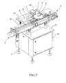
- the apparatus of the present invention comprises an anti-reflective enclosure 1 which surrounds the whole of the functional devices of the apparatus, so that communication with the outside of said enclosure will take place exclusively by means of the passages for the entry 2 and exit 3 of the containers, nevertheless having a front door 4 for inspection and maintenance of the apparatus, which will customarily be arranged on adjustable-height feet 5 to enable it to be easily levelled.
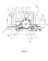
- the apparatus comprises a revolving plate 6 which will pick up in succession the containers proceeding from the entry 2 and which by way of example have been shown with the numbers 7, 7', 7".
- the assembly 8 for the pre-ionisation electrode, the artificial vision camera 9 and the electrode holder 10 for the formation of the arc On the periphery of the circular plate 6 is arranged the assembly 8 for the pre-ionisation electrode, the artificial vision camera 9 and the electrode holder 10 for the formation of the arc.
- the respective electrodes can be seen more clearly in Figure 5, being designated by the numbers 11 and 12.
- the whole assembly of devices is mounted on the table 13, which forms the upper part of a base casing 14 carrying the control devices for the machine.
- the assembly formed by the plate 6, the pre-ionisation station 8, the CCD camera 9 and the high voltage electrode assembly 10 is mounted on an exchangeable intermediate insulating base 15', and this is in turn mounted on the base 15, which is incorporated in the support panel 13 by means of the adjustable feet 16, variable in number, corresponding to four in number in the example shown.
- the CCD camera mounted inside the protective casing 9 has been shown by the number 17 in Figure 6, being able to capture the formation of the arc inside the container through the front protection 18.
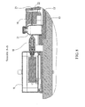
- the revolving assembly 6 has an upper plate 19, Figures 5 and 8, bearing re-entrants 20 intended for the individual pick-up of the containers such as the container 21 shown in Figures 7 and 8, which is guided on the exchangeable insulating base 15' and which is in contact with a disc functioning as an earth electrode 23, located at height above that of the product contained in the container 21, between the plates 19 and 22, while the electrode, for example, the pre-ionisation electrode 11 and also the main electrode 12, together with the disc 23, determine the route by which will pass the discharge, which will be captured by the vision camera for the purpose of its comparison and determination of whether or not it reaches the degree of vacuum desired in the container.
- a disc functioning as an earth electrode 23 located at height above that of the product contained in the container 21, between the plates 19 and 22, while the electrode, for example, the pre-ionisation electrode 11 and also the main electrode 12, together with the disc 23, determine the route by which will pass the discharge, which will be captured by the vision camera for the purpose of its comparison and determination of whether or not it reaches the degree of
- the invention may be produced both with movable-type support means for the earth electrode and with fixed-type support means.
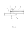
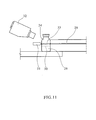
- Figures 9 to 13 show diagrammatically the different stages of the process, it being possible to see firstly the entry of the containers in alignment on an entry guide 25, the recipients being designated by the numbers 24, 24', 24".
- the pre-ionisation electrode 26, which corresponds to the electrode 11 shown in Figure 5 applies a voltage for pre-ionisation of the container, it being possible to observe the formation of the arc 27 between said electrode 26 and the electrode 28 arranged opposite.
- the content of the lyophilised material 29 inside the container 24 determines that its level 30 remains below the zone of influence of the arc.
- the containers are then fed to the stage of inspection with energising of the container in which the energising electrode 31 will apply a high voltage to create the discharge 33, which will be evaluated by the CCD camera 32, qualitatively comparing the luminous intensity of the arc formed 33 with the values determined previously in accordance with the criterion for acceptance and rejection, which will effect the qualification of the container 24 as acceptable or to be rejected.
- It may therefore represent: a) the expulsion of the container 24 into the zone in which there is sufficient room for it (as can be observed in Figure 12), after having generated an expulsion impulse, or b) the continuation of the containers to subsequent stages, as can be observed in Figure 13, in which the alignment of the containers 24, 24' 24" is continued, since there is no expulsion of any of them.
- Figure 14 shows an alternative embodiment with double head, that is to say, equipped with two circular plates 34 and 34' of similar structure to that explained previously, each equipped with its own feeding system 35 and 35' and its own outlets for accepted containers 36 and 36' which may optionally emerge, combined together, in a single outlet 37.
- Figure 15 shows an embodiment of a feed for the apparatus in multiple form, that is to say, instead of the feeding of containers aligned in a single line per plate, providing multiple feeding by means of multiple lines of containers as shown with the guide 38 in Figure 15 which will make it possible to feed the containers to the plate 39, for example, two by two or in general in a variable number greater than one.
Landscapes
- Physics & Mathematics (AREA)
- General Physics & Mathematics (AREA)
- Investigating Materials By The Use Of Optical Means Adapted For Particular Applications (AREA)
- Investigating Or Analysing Materials By Optical Means (AREA)
Applications Claiming Priority (1)
| Application Number | Priority Date | Filing Date | Title |
|---|---|---|---|
| ES200502702A ES2254035B1 (es) | 2005-11-07 | 2005-11-07 | "procedimiento y aparato para evaluar el grado de vacio en cuerpos cerrados de paredes transparentes". |
Publications (2)
| Publication Number | Publication Date |
|---|---|
| EP1783477A2 true EP1783477A2 (fr) | 2007-05-09 |
| EP1783477A3 EP1783477A3 (fr) | 2016-01-06 |
Family
ID=36578895
Family Applications (1)
| Application Number | Title | Priority Date | Filing Date |
|---|---|---|---|
| EP06380281.3A Withdrawn EP1783477A3 (fr) | 2005-11-07 | 2006-10-31 | Procédé et appareil d'évaluation du degré de vide dans un corps clos à parois transparentes |
Country Status (3)
| Country | Link |
|---|---|
| US (1) | US7323881B2 (fr) |
| EP (1) | EP1783477A3 (fr) |
| ES (1) | ES2254035B1 (fr) |
Cited By (2)
| Publication number | Priority date | Publication date | Assignee | Title |
|---|---|---|---|---|
| CN103792051A (zh) * | 2014-02-18 | 2014-05-14 | 珠海格力电器股份有限公司 | 一种卤素管气密性测试方法及测试装置 |
| IT201800007905A1 (it) * | 2018-08-06 | 2020-02-06 | Convel Srl | Apparecchiatura per l’ispezione di contenitori e procedimento per la realizzazione di una pista per detta apparecchiatura |
Families Citing this family (7)
| Publication number | Priority date | Publication date | Assignee | Title |
|---|---|---|---|---|
| US20110146835A1 (en) * | 2008-08-23 | 2011-06-23 | Robert Terzini | Automated pharmacy drug handling and prescription verification system and method |
| JP5299241B2 (ja) * | 2008-11-28 | 2013-09-25 | 株式会社島津製作所 | パーティクル計数装置 |
| US8878926B2 (en) * | 2010-09-17 | 2014-11-04 | Applied Materials, Inc. | Apparatus and method for analyzing thermal properties of composite structures |
| DE102013014473B4 (de) * | 2013-08-29 | 2021-04-15 | INTRAVIS Gesellschaft für Lieferungen und Leistungen von bildgebenden und bildverarbeitenden Anlagen und Verfahren mbH | Prüfvorrichtung für Gefäße |
| KR101869613B1 (ko) * | 2016-11-30 | 2018-06-21 | 한국표준과학연구원 | 진공방전관을 이용한 압력센서 |
| KR102045910B1 (ko) * | 2018-02-06 | 2019-11-18 | 황지연 | 바이알 진공검사 시스템 |
| CN112014038A (zh) * | 2020-08-22 | 2020-12-01 | 郑州三骏能源科技有限公司 | 一种新能源汽车电控箱检测设备 |
Family Cites Families (16)
| Publication number | Priority date | Publication date | Assignee | Title |
|---|---|---|---|---|
| US2734628A (en) * | 1956-02-14 | schlayer | ||
| GB333938A (en) * | 1929-05-23 | 1930-08-25 | Richard Douglas Scoble Hodgins | Improvements in or relating to apparatus for sorting apples, eggs or other suitable articles |
| DE2717436A1 (de) * | 1976-04-26 | 1977-11-10 | Varian Associates | Verfahren und vorrichtung zur bestimmung des partialdruckes eines gases zur vakuummessung, leckanzeige, messung der niederschlagsrate o.dgl. |
| US4152213A (en) * | 1977-03-10 | 1979-05-01 | Johnston Laboratories, Inc. | Vacuum detection of bacteria |
| US4517827A (en) * | 1983-03-24 | 1985-05-21 | General Foods Incorporated | Apparatus and method for testing for leakages in hermetically-sealed packages |
| US4546319A (en) * | 1983-11-04 | 1985-10-08 | Pfaff Ernest H | Vacuum testing method and apparatus |
| GB2180063B (en) * | 1985-07-31 | 1989-08-16 | Toshiba Kk | Lamp quality judgement method and apparatus therefor |
| US4882543A (en) * | 1988-08-01 | 1989-11-21 | Electro-Technic Products, Inc. | Vacuum testing apparatus having a test enclosure with a rotatable sleeve |
| JPH0257533A (ja) * | 1988-08-22 | 1990-02-27 | Taiyo Fishery Co Ltd | 密閉容器のリーク検査方法 |
| JPH02147964A (ja) * | 1988-11-30 | 1990-06-06 | Mitsubishi Heavy Ind Ltd | マイクロ波電界分布の測定方法 |
| DE4126275A1 (de) * | 1991-08-08 | 1993-02-11 | Hoechst Ag | Verfahren zum quantitativen messen eines vakuums in geschlossenen behaeltern |
| JP3168751B2 (ja) * | 1992-04-02 | 2001-05-21 | 富士電機株式会社 | 真空バルブの真空漏れ検知方法および装置 |
| EP0786654A3 (fr) * | 1997-05-07 | 1997-12-10 | Martin Lehmann | Système d'essai d'étanchéité pour des récipients fermés |
| GB9710316D0 (en) * | 1997-05-21 | 1997-07-16 | Powell Alexander R | Vaccum detection system |
| EP0962756A1 (fr) * | 1998-05-08 | 1999-12-08 | Kraft Foods, Inc. | Méthode d'examen de fuite non-destructif d'emballage sous vide |
| DE19853049C2 (de) * | 1998-11-17 | 2001-09-06 | Joachim Franzke | Vorrichtung und Verfahren zum Feststellen eines Lecks sowie Verwendung einer solchen Vorrichtung für die Lecksuche |
-
2005
- 2005-11-07 ES ES200502702A patent/ES2254035B1/es not_active Expired - Fee Related
-
2006
- 2006-10-31 EP EP06380281.3A patent/EP1783477A3/fr not_active Withdrawn
- 2006-11-06 US US11/556,772 patent/US7323881B2/en not_active Expired - Fee Related
Non-Patent Citations (1)
| Title |
|---|
| None * |
Cited By (2)
| Publication number | Priority date | Publication date | Assignee | Title |
|---|---|---|---|---|
| CN103792051A (zh) * | 2014-02-18 | 2014-05-14 | 珠海格力电器股份有限公司 | 一种卤素管气密性测试方法及测试装置 |
| IT201800007905A1 (it) * | 2018-08-06 | 2020-02-06 | Convel Srl | Apparecchiatura per l’ispezione di contenitori e procedimento per la realizzazione di una pista per detta apparecchiatura |
Also Published As
| Publication number | Publication date |
|---|---|
| EP1783477A3 (fr) | 2016-01-06 |
| ES2254035B1 (es) | 2007-02-16 |
| US7323881B2 (en) | 2008-01-29 |
| ES2254035A1 (es) | 2006-06-01 |
| US20070103169A1 (en) | 2007-05-10 |
Similar Documents
| Publication | Publication Date | Title |
|---|---|---|
| KR100745586B1 (ko) | 전지 검사장치 | |
| US10718717B2 (en) | Inspection of sealing quality in blister packages | |
| JP3518596B2 (ja) | ソフトバッグ総合検査システム | |
| US9170213B2 (en) | Sensor device for a packaging machine designed as a capsule filling and sealing machine or for a capsule control device | |
| US4736851A (en) | Process and apparatus for the automatic inspection by transparency contrast in particular of containers | |
| CA2111746C (fr) | Systeme et methode pour l'inspection de lentilles ophthalmiques | |
| KR101287464B1 (ko) | 이차 건전지용 캔의 자동검사장치 | |
| KR101717610B1 (ko) | 전자선 살균 장치 | |
| US7323881B2 (en) | Process and apparatus for evaluating the degree of vacuum in closed bodies with transparent walls | |
| US8135206B2 (en) | Machine for inspecting glass containers | |
| US5819953A (en) | Method and apparatus for sorting capsules | |
| US20100194878A1 (en) | Machine For Inspecting Glass Containers | |
| KR20150023696A (ko) | 용기 및/또는 그 내용물 내 결함의 x-선 검출 | |
| CN1110063A (zh) | 用以检测表面缺陷的设备 | |
| CN105537139A (zh) | 一种瓶装药物分拣机及分拣方法 | |
| US20130015108A1 (en) | Device for extracting containers | |
| KR20090107400A (ko) | 기판 검사 장치 및 이를 갖는 공정 설비 | |
| MXPA05005068A (es) | Dispositivo para examinar envases llenados mediante rayos x emitidos oblicuamente. | |
| JP2002228761A (ja) | X線異物検出装置及び該装置における不良品検出方法 | |
| KR102552557B1 (ko) | 검사 방법 | |
| JP2003536069A (ja) | 食品用x線検査装置 | |
| KR20160026090A (ko) | 캡 검사장치 | |
| US3481467A (en) | Photocell inspection device for glassware | |
| CN217616148U (zh) | 药瓶检测装置 | |
| KR101764238B1 (ko) | 정량포장이 가능한 약품 검사장치 |
Legal Events
| Date | Code | Title | Description |
|---|---|---|---|
| PUAI | Public reference made under article 153(3) epc to a published international application that has entered the european phase |
Free format text: ORIGINAL CODE: 0009012 |
|
| AK | Designated contracting states |
Kind code of ref document: A2 Designated state(s): AT BE BG CH CY CZ DE DK EE ES FI FR GB GR HU IE IS IT LI LT LU LV MC NL PL PT RO SE SI SK TR |
|
| AX | Request for extension of the european patent |
Extension state: AL BA HR MK YU |
|
| RAP1 | Party data changed (applicant data changed or rights of an application transferred) |
Owner name: GRIFOLS, S.A. |
|
| PUAL | Search report despatched |
Free format text: ORIGINAL CODE: 0009013 |
|
| AK | Designated contracting states |
Kind code of ref document: A3 Designated state(s): AT BE BG CH CY CZ DE DK EE ES FI FR GB GR HU IE IS IT LI LT LU LV MC NL PL PT RO SE SI SK TR |
|
| AX | Request for extension of the european patent |
Extension state: AL BA HR MK RS |
|
| RIC1 | Information provided on ipc code assigned before grant |
Ipc: G01M 3/40 20060101AFI20151127BHEP |
|
| 17P | Request for examination filed |
Effective date: 20160531 |
|
| RBV | Designated contracting states (corrected) |
Designated state(s): AT BE BG CH CY CZ DE DK EE ES FI FR GB GR HU IE IS IT LI LT LU LV MC NL PL PT RO SE SI SK TR |
|
| AKX | Designation fees paid |
Designated state(s): AT BE BG CH CY CZ DE DK EE ES FI FR GB GR HU IE IS IT LI LT LU LV MC NL PL PT RO SE SI SK TR |
|
| AXX | Extension fees paid |
Extension state: HR Extension state: MK Extension state: AL Extension state: BA Extension state: RS |
|
| 17Q | First examination report despatched |
Effective date: 20180411 |
|
| STAA | Information on the status of an ep patent application or granted ep patent |
Free format text: STATUS: THE APPLICATION IS DEEMED TO BE WITHDRAWN |
|
| 18D | Application deemed to be withdrawn |
Effective date: 20180822 |