EP1783545A1 - Cadre pour le positionnement de composants optiques d un dispositif de projection - Google Patents
Cadre pour le positionnement de composants optiques d un dispositif de projection Download PDFInfo
- Publication number
- EP1783545A1 EP1783545A1 EP05447245A EP05447245A EP1783545A1 EP 1783545 A1 EP1783545 A1 EP 1783545A1 EP 05447245 A EP05447245 A EP 05447245A EP 05447245 A EP05447245 A EP 05447245A EP 1783545 A1 EP1783545 A1 EP 1783545A1
- Authority
- EP
- European Patent Office
- Prior art keywords
- frame
- polymer
- layer
- deposited layer
- compound
- Prior art date
- Legal status (The legal status is an assumption and is not a legal conclusion. Google has not performed a legal analysis and makes no representation as to the accuracy of the status listed.)
- Withdrawn
Links
Images


Classifications
-
- G—PHYSICS
- G03—PHOTOGRAPHY; CINEMATOGRAPHY; ANALOGOUS TECHNIQUES USING WAVES OTHER THAN OPTICAL WAVES; ELECTROGRAPHY; HOLOGRAPHY
- G03B—APPARATUS OR ARRANGEMENTS FOR TAKING PHOTOGRAPHS OR FOR PROJECTING OR VIEWING THEM; APPARATUS OR ARRANGEMENTS EMPLOYING ANALOGOUS TECHNIQUES USING WAVES OTHER THAN OPTICAL WAVES; ACCESSORIES THEREFOR
- G03B21/00—Projectors or projection-type viewers; Accessories therefor
- G03B21/14—Details
- G03B21/145—Housing details, e.g. position adjustments thereof
-
- G—PHYSICS
- G03—PHOTOGRAPHY; CINEMATOGRAPHY; ANALOGOUS TECHNIQUES USING WAVES OTHER THAN OPTICAL WAVES; ELECTROGRAPHY; HOLOGRAPHY
- G03B—APPARATUS OR ARRANGEMENTS FOR TAKING PHOTOGRAPHS OR FOR PROJECTING OR VIEWING THEM; APPARATUS OR ARRANGEMENTS EMPLOYING ANALOGOUS TECHNIQUES USING WAVES OTHER THAN OPTICAL WAVES; ACCESSORIES THEREFOR
- G03B21/00—Projectors or projection-type viewers; Accessories therefor
- G03B21/005—Projectors using an electronic spatial light modulator but not peculiar thereto
Definitions
- the present invention relates to frames for positioning optical components of a projection device and to a method to provide a frame for positioning optical components of a projection device.
- Frames of projection devices such as digital mirror device or digital micromirror device projector (hereafter DMD), projectors using a liquid crystal display (hereafter LCD), projectors using a liquid crystal on Silicon display (hereafter Lcos) and the like, are at present made out of one or more metal or polymer parts.
- Polymer materials such as thermoplastic or thermoset polymer material, are preferred, because of the weight and cost of these materials.
- the frames as a whole or in part are provided by transfer or injection molding techniques of thermoset or thermoplastic polymer compounds.
- Thermoset materials are preferred, such as BMC or TMC compounds. This is because thermoset parts, once molded, show few or no crimping during cooling. This enables use of smaller dimension tolerances in designing the frames.
- a surprisingly negative effect of light from the illumination source used with the optical components was noticed on the polymer material of the frame.
- the illumination of the frame creates however aging and degradation of the polymer material of the frame, because of the irradiation and thermal energy from the illumination source used with the optical components.
- an irradiation resistant material such as a self adhesive Aluminium tape.
- This tape protects indeed the underlying polymer material, however it has as disadvantage that the tape cannot follow or match the usually very complex shape of the frame part very accurately. Furthermore, the use of an aluminium tape at present used is very tedious and labour-intensive.
- the frame according to the present invention is at least partially provided out of a polymer material, which polymer material provides at least a part of the outer surface of the frame, hereafter the polymer outer surface.
- a polymer material which polymer material provides at least a part of the outer surface of the frame, hereafter the polymer outer surface.
- at least a part of the polymer outer surface is provided with a deposited layer, e.g. a lacquer layer, of UV-protection material for preventing UV-light emanating from said optical components from irradiating the polymer material used in the frame. It has been found that when the UV-part of the light spectrum is prevented from irradiating the polymer frame by means of a deposited layer, e.g.
- the polymer does not show aging or degradation (or shows reduced aging or degradation) due to the irradiation of the polymer by the illumination of the optical components, nor does it suffer from delamination of the deposited layer, e.g. lacquer layer, i.e. release of the deposited layer, e.g. lacquer layer from the underlying polymer surface.
- the outer polymer surface keeps its shape and dimensions over time, resulting in positioning points, projections, supports or other identical means, being present at the outer polymer surface, to maintain their position and shape.
- the optical and possibly other components remain in a correct and stable position over time without deviation from their original position due to aging or degradation of the polymer material.
- optical components is to be understood in its broadest sense, meaning e.g. lamps, lenses, illumination filters, prisms, mirrors, light modulating means such as LCD-elements and/or DMD-elements.
- other components such as fans, motors, sensors, microswitches, mechanical supports for pcb's or other components may be positioned on the frame.
- positioning points, projections, supports or other identical means is to be understood as reference points, struts, projections, or any other possible means, which serves as reference point or buffers, helping to position the optical or other components, which are to be positioned on the frame, or which provide support to the optical or other components to maintain their position.
- positioning points may be fixed points, against which a component is statically positioned, or may be buffers, circumscribing the range in which a dynamic component may move, this is translate or rotate.
- UV-light is to be understood as light having a wavelength in the range of 425 nm to 10 nm. It is understood that according to the present invention, the lacquer layer is to prevent UV-light with a wavelength in the near UV-spectrum, being 425 nm to 200 nm, to irradiate the polymer material of the frame, as this is the spectrum which is most likely present in the light used be the projection devices.
- deposited layer is to be understood as a layer deposited directly on the polymer outer surface.
- the term "deposited” is to be understood as a layer being provided using a technique such as e.g. spraying on the layer, painting, sputtering, cladding, vapour deposition of the layer, e.g. by chemical of physical vapour deposition, by submerging or dipping the part of the polymer outer surface in a liquid, which liquid comprises the UV-protective material, or providing the layer by a coating process such as spin-coating, solvent coating or powder coating, electrostatic powder coating as well as by other means such as by electrochemical deposition, by plating, etc.
- the term "cladding” is to be understood as a technique where powder, e.g. metal powder, is blown to the surface and cured to provide a sintered like layer. As an example, laser cladding may be used, where metal powder is blown to the surface and together with the power of a laser beam is cured, resulting in a sintered like layer.
- the deposited layer e.g. lacquer layer is provided in a thin layer
- this is a layer having an average thickness in the range of 1 ⁇ m to 50 ⁇ m, more preferred in the range of 1 ⁇ m to 30 ⁇ m, such as in the range of 1 ⁇ m to 20 ⁇ m, e.g. 10 ⁇ m.
- Such thin layers have the advantage that they can be provided in a uniform and predictable way, which further improves the correctness and stable positioning over time without deviation from their original position of the positioning points, projections, supports or other identical means.
- a UV-reflective or a UV-absorbing deposited layer e.g. a UV-reflective or a UV-absorbing lacquer layer
- the lacquer layer may be provided using different techniques such as spraying of the lacquer, vapour deposition of a lacquer layer, e.g. by chemical of physical vapour deposition, by submerging or dipping the part of the polymer outer surface in a liquid, which liquid comprises lacquer and a solvent, or providing a lacquer layer by spin-deposited layer or powder deposited layer.
- the deposited layer may also be a reflective layer, e.g. a metal layer provided by chemical or physical deposition, electrochemical deposition, plating, sputtering, cladding, etc.
- the lacquer layer preferably is a thermally stable lacquer layer, more preferred a silicon-based lacquer.
- the deposited layer can be a Chromium-, Nickel-, Copper-, aluminium- or Magnesium-based layer.
- the deposited layer may be a layer of Chromium, Nickel, Copper, aluminium or Magnesium, directly applied on the surface.
- thermally stable is to be understood as being resistant to temperatures up to 200°C. In some areas, resistance to even higher temperatures may be envisaged. Especially in the area close to a lamp, local temperature can be high. Normally these areas are cooled with fans, but the deposited layers should however be capable of withstanding not only UV light but also heat. On hot spots, temperatures could be even very high (250 to 350 degrees Celsius).
- the frame is at least partially provided out of a polymer material, which polymer material is at least partially present at the outer surface of the frame, being the outer polymer surface. Possibly, even preferably, the whole frame is provided out of polymer material.
- the polymer material may be either a thermoset polymer compound, such as polyester compounds, and may optionally also comprise inorganic reinforcement such as glass-reinforcing elements, e.g. glass fibers or glass particle reinforcement.
- BMC bulk molding compound
- TMC thick molding compound
- the polymer compound is a polyester compound, such as a compound consisting of Vinyl Esther with about 20 % glass.
- a thermoplastic compound may be used such as glass fiber reinforced PPS (PolyPhenylSulfide), used for lamp housings.
- Projection devices as subject of the present invention are to be understood as any kind of projection devices, such as e.g. digital mirror device or digital micromirror device projector, projectors using a liquid crystal display, projectors using a Liquid crystal on Silicon (LCOS) display and the like.
- projection devices such as e.g. digital mirror device or digital micromirror device projector, projectors using a liquid crystal display, projectors using a Liquid crystal on Silicon (LCOS) display and the like.
- LCOS Liquid crystal on Silicon
- a frame for positioning optical components of a projection device comprising the steps of
- the forming may be any method of molding such as injection or transfer molding.
- the forming of the frame may also be provided by assembly of several polymer parts.
- the frame may be assembled together to form a frame completely out of polymer material.
- the frame is provided as a one-piece transfer or injection molded frame.
- the frame may comprise also non-polymer parts, such as metal parts (e.g. insert nuts).
- At least an exposed part of the polymer outer surface of the polymer part of the frame is provided with a deposited layer, such as a lacquer layer, by using different techniques such as spraying, vapour deposition, e.g. by chemical of physical vapour deposition, by submerging or dipping the part of the polymer outer surface in a bath comprising the UV-protection material of the layer, or providing a layer by spin-coating or powder coating.
- the deposited layer may also be a reflective layer such as a metal layer, e.g. provided by electrochemical deposition, plating, sputtering or cladding. It is understood that the layer may be provided by only one of the techniques, or by combining two or more techniques to provide the layer.
- the deposited layer e.g. lacquer layer may be provided by the different techniques prior or after assembling two or more parts of the frame.
- the present invention is based on the finding that when using conventional aluminium self-adhesive tape very complex or small positioning points or projections can be covered by the tape to such an extent, that they can no longer fulfil their function of positioning the component adequately.
- the thermal energy from the illumination source may cause the temperature at the aluminium tape to rise, causing the self-adhesive glue to release.
- air is trapped under the tape, this air forms bubbles by expanding when temperature rises. This increases even more the tape not following or matching the surface of the underlying part of the frame.
- the irradiation of the polymer frame by the illumination source of the projector can result in degradation of the frame material and lead to distortions or pulverised material of the frame.
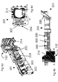
- FIG. 1 an inner side of a projection device comprising an optical frame 100 is shown.
- frame parts 110, 120 and 130 for positioning optical components of a projection device are shown.
- Frame parts 110 and 120 are frame parts to hold a lamp, whose illumination is used to generate images, which are to be projected by the projection device.
- the light provided by lamps held in frame parts 110 and 120 is guided by several optical components in the frame part 130, towards a mirror 131, being an optical component, present at the end of frame part 130.
- This frame part 130 is shown in detail in Fig. 2.
- the two other frame parts 110 and 120 for holding lamps are assembled, in this embodiment fixed to the frame part 130 at two opposed end surfaces 132 and 133.
- the frame part 130 is actually provided out of two parts 201 and 202.
- Frame part 201 As frame part 201 is shown in Fig. 3, several optical components (references 210 in the figures indicate some of the optical components) are hold in the frame part 201, next to the mirror 131.
- Frame part 202 is assembled to frame part 201 by means of a number of bolts, having the inner surfaces 204 and 205 of respectively frame parts 201 and 202 facing each other, creating a tunnel by which the light provided by the lamps held in frame parts 110 and 120 is guided to the mirror 131.
- Frame parts 201 and 202 of frame part 130, and frame parts 110 and 120 are provided by any suitable forming technique and by any suitable material or materials of which a thermoset polymer compound is preferred, e.g. BMC material, e.g. BMC comprising polyester and glass reinforcing elements, or out of TMC, e.g. TMC consisting of vinyl ester with about 20 % glass.
- BMC material e.g. BMC comprising polyester and glass reinforcing elements
- TMC e.g. TMC consisting of vinyl ester with about 20 % glass.
- the forming may include an injection or transfer molding technique.
- the surfaces 132, 133, 204, 205, 214 and 215, being polymer outer surfaces, may comprise positioning points, projections, supports or other identical means (references 300 in the figures indicate some of the positioning points, projections, supports or other identical means).
- some parts of the outer surface of the polymer injection molded parts are provided with a deposited layer, e.g. a lacquer layer, of UV-protective material. This is shown more into detail in Fig. 4 and Fig. 5.
- Fig. 4a shows schematically a perspective view of frame part 201, more in detail in Fig. 4b, Fig. 4b, Fig. 4d and a cross section of frame part 201 according to the plane AA' is shown in Fig. 4e.
- Fig. 5a shows schematically a perspective view of frame part 202, more in detail in Fig. 5b, Fig. 5b, Fig. 5d and a cross section of frame part 202 according to the plane BB' is shown in Fig. 5e.
- the surface 204 and 205 of parts 201 and 202 which provide the tunnel by which the light provided by the lamps held in frame parts 110 and 120 is guided to the mirror 131 are provided with a UV-protective deposited layer, e.g. lacquer layer.
- a UV-protective deposited layer e.g. lacquer layer.
- the surface 214 and 215 at the inner side of part of the frames 201 and 202, in which the light of the lamps is guided over an angle into the tunnel is provided with a similar deposited layer, e.g. lacquer layer.
- the surfaces 132 and 133 of the frames 201 and 202 against which the frame parts 110 and 120 comprising the lamps are amounted are provided with a similar UV-protective deposited layer, e.g. lacquer layer.
- This deposited layer e.g. lacquer layer can be a UV-absorbing lacquer layer, such as the product "DK52910" available from nv Flanders Color, Kortrijkstraat 380, 8560 Wevelgem, Belgium.
- DK52910 is a silicon based lacquer layer, comprising a silicone resin, comprising silicon and silicon oxide, having methyl- and ethyl and/or methyl phenyl side groups is provided. The side groups make the lacquer liquid.
- the product comprises filler being carbon black.
- a lacquer layer of a silicon and silicon oxide matrix, being a stoichiometric inorganic (SiO2)n-matrix is thus obtained, in which the carbon black filler is trapped.
- the so provided deposited layer is resistant to UV, protects the underlying polymer material from UV radiation, and is thermally stable to about 450°C.
- using a lacquer comprising an Aluminium-filler may provide a similar silicon based lacquer layer. After being cured, this layer is resistant to temperatures of about 650°C.
- using a lacquer comprising a Fe-Mn oxide black-filler may provide a similar silicon based lacquer layer. After being cured, this layer is resistant to temperatures of about 500°C.
- the deposited layer can have an average thickness in the range of more than 10 ⁇ m, such as e.g. more than 15 ⁇ m to less than 25 ⁇ m, e.g. less than 20 ⁇ m, e.g. 12 ⁇ m.
- Thicker layers are not necessarily excluded from the present invention, but if the thickness is more than 25 ⁇ m or even more than 100 ⁇ m, the layers may tend to break because of thermal stresses during heating and cooling.
- the polymer surface may be blasted, e.g. mildly sand blasting, prior to deposition of the layer.
- a UV-reflecting deposited layer e.g. a lacquer or metal layer is provided such as e.g. a Chromium layer provided by vapour deposition.
- each surface of the outer polymer surface which may be illuminated or irradiated by the light emanating by an optical component held by the frame, is provided with a UV-protective deposited layer, e.g. lacquer layer.
- a UV-protective deposited layer e.g. lacquer layer.
- the surfaces 204 and 205 need not be provided with a deposited layer, e.g. lacquer layer.
- Spraying the lacquer onto the surfaces 132, 133, 214, 215 and possibly 204 and 205 is a preferred method of providing the UV protective deposited layer.
- a part of the lacquer layer a the surfaces 132 and 133 is provided by emerging or dipping the frame parts 201 and 202 in a bath of liquid, which liquid comprises the lacquer and a solvent.
- a dip coated layer or layer provided by emerging is so provided. This emerging or dipping is done over an appropriate depth 301, so the surface onto which the lacquer is to be provided, has been wetted.
- chemical or physical vapour deposition, or spin-coating or powder coating may be used to provide the required surfaces with a lacquer layer.
- the frame 100 as described above was provided by first providing the several frame parts 110, 120, 201 and 202 by injection of any suitable material or materials of which a thermoset polymer compound is preferred, e.g. BMC material, e.g. BMC comprising polyester and glass reinforcing elements, or out of TMC, e.g. TMC consisting of vinyl ester with about 20 % glass, in appropriately dimensioned molds.
- BMC material e.g. BMC comprising polyester and glass reinforcing elements
- TMC e.g. TMC consisting of vinyl ester with about 20 % glass
- the surfaces 133, 214, 215 and possibly 204 and 205 are provided with a lacquer layer, preferably by spraying the lacquer onto the surfaces in a substantially equal thickness. Possibly, the lacquer layer is hereafter cured, e.g. by thermal treatment of the frame parts.
- a lacquer layer can be a UV-absorbing lacquer layer of the product "DK52910" available from nv Flanders Color, Kortrijkstraat 380, 8560 Wevelgem, Belgium is sprayed to the surfaces 133, 214, 215 and possibly 204 and 205, and thereafter, subjecting the frame parts to a temperature of 190°C during 20 minutes cures the lacquer layer of the frame parts.
- the lacquer layer may be provided to the surfaces 132 and 133 by emerging or dipping the frame parts 201 and 202 in a bath of liquid, which liquid comprises the lacquer and a solvent. Also chemical or physical vapour deposition, or spin-coating or powder coating may be used to provide the required surfaces with a lacquer layer.
- the frame parts are assembled, together with the optical and possibly other components, in order to provide the optical piece of equipment of the projection device as subject of the present invention.
Landscapes
- Physics & Mathematics (AREA)
- General Physics & Mathematics (AREA)
- Projection Apparatus (AREA)
- Non-Portable Lighting Devices Or Systems Thereof (AREA)
- Mounting And Adjusting Of Optical Elements (AREA)
- Lens Barrels (AREA)
Priority Applications (3)
| Application Number | Priority Date | Filing Date | Title |
|---|---|---|---|
| EP05447245A EP1783545A1 (fr) | 2005-11-04 | 2005-11-04 | Cadre pour le positionnement de composants optiques d un dispositif de projection |
| US11/591,506 US20070103654A1 (en) | 2005-11-04 | 2006-11-02 | Frame for positioning optical components of a projection device |
| JP2006299451A JP2007140509A (ja) | 2005-11-04 | 2006-11-02 | 投影装置の光学部品を位置決めするためのフレームおよびその方法 |
Applications Claiming Priority (1)
| Application Number | Priority Date | Filing Date | Title |
|---|---|---|---|
| EP05447245A EP1783545A1 (fr) | 2005-11-04 | 2005-11-04 | Cadre pour le positionnement de composants optiques d un dispositif de projection |
Publications (1)
| Publication Number | Publication Date |
|---|---|
| EP1783545A1 true EP1783545A1 (fr) | 2007-05-09 |
Family
ID=35976570
Family Applications (1)
| Application Number | Title | Priority Date | Filing Date |
|---|---|---|---|
| EP05447245A Withdrawn EP1783545A1 (fr) | 2005-11-04 | 2005-11-04 | Cadre pour le positionnement de composants optiques d un dispositif de projection |
Country Status (3)
| Country | Link |
|---|---|
| US (1) | US20070103654A1 (fr) |
| EP (1) | EP1783545A1 (fr) |
| JP (1) | JP2007140509A (fr) |
Citations (4)
| Publication number | Priority date | Publication date | Assignee | Title |
|---|---|---|---|---|
| US4029956A (en) * | 1975-03-24 | 1977-06-14 | Alos Ag | Light fixture for projection device |
| EP1129790A2 (fr) * | 1999-12-27 | 2001-09-05 | Ce.Te.V. Centro Tecnologie Del Vuoto | Structure de film mince et procédé pour un traitement résistant à l'abrasion et aux UV sur un substrat plastique |
| US20020018183A1 (en) * | 2000-07-07 | 2002-02-14 | Seiko Epson Corporation | Polarization-coverting unit and projector using the same |
| US20050007680A1 (en) * | 2003-07-08 | 2005-01-13 | Jun Naganuma | Lens barrel |
Family Cites Families (9)
| Publication number | Priority date | Publication date | Assignee | Title |
|---|---|---|---|---|
| US3215529A (en) * | 1960-07-18 | 1965-11-02 | Kalvar Corp | Color photographic material |
| US3460961A (en) * | 1965-04-21 | 1969-08-12 | Monsanto Co | Process of coating a substrate with a polymeric ultraviolet light barrier coating and the coated substrate |
| GB1335668A (en) * | 1970-06-09 | 1973-10-31 | Agfa Gevaert | Ultraviolet-absorbing filter layers |
| GB1346764A (en) * | 1970-06-09 | 1974-02-13 | Agfa Gevaert | Ultraviolet absorbing filter layers |
| US4463055A (en) * | 1983-04-27 | 1984-07-31 | Hodges Marvin P | Reflective film and method of applying same |
| US5016292A (en) * | 1989-12-07 | 1991-05-21 | Mark Rademacher | Combination gamma, ultraviolet and X-radiation goggles |
| US6468718B1 (en) * | 1999-02-04 | 2002-10-22 | Clariant Finance (Bvi) Limited | Radiation absorbing polymer, composition for radiation absorbing coating, radiation absorbing coating and application thereof as anti-reflective coating |
| US6270888B1 (en) * | 1997-08-07 | 2001-08-07 | Dupont Teijin Films Us Limited Partner | Polymeric film |
| US7476889B2 (en) * | 1998-12-07 | 2009-01-13 | Meridian Research And Development | Radiation detectable and protective articles |
-
2005
- 2005-11-04 EP EP05447245A patent/EP1783545A1/fr not_active Withdrawn
-
2006
- 2006-11-02 JP JP2006299451A patent/JP2007140509A/ja not_active Withdrawn
- 2006-11-02 US US11/591,506 patent/US20070103654A1/en not_active Abandoned
Patent Citations (4)
| Publication number | Priority date | Publication date | Assignee | Title |
|---|---|---|---|---|
| US4029956A (en) * | 1975-03-24 | 1977-06-14 | Alos Ag | Light fixture for projection device |
| EP1129790A2 (fr) * | 1999-12-27 | 2001-09-05 | Ce.Te.V. Centro Tecnologie Del Vuoto | Structure de film mince et procédé pour un traitement résistant à l'abrasion et aux UV sur un substrat plastique |
| US20020018183A1 (en) * | 2000-07-07 | 2002-02-14 | Seiko Epson Corporation | Polarization-coverting unit and projector using the same |
| US20050007680A1 (en) * | 2003-07-08 | 2005-01-13 | Jun Naganuma | Lens barrel |
Non-Patent Citations (1)
| Title |
|---|
| ANMA H ET AL: "PREPARATION OF ZNO THIN FILMS DEPOSITED BY PLASMA CHEMICAL VAPOR DEPOSITION FOR APPLICATION TO ULTRAVIOLET-CUT COATING", JAPANESE JOURNAL OF APPLIED PHYSICS, JAPAN SOCIETY OF APPLIED PHYSICS, TOKYO, JP, vol. 40, no. 10, PART 1, October 2001 (2001-10-01), pages 6099 - 6103, XP001091805, ISSN: 0021-4922 * |
Also Published As
| Publication number | Publication date |
|---|---|
| JP2007140509A (ja) | 2007-06-07 |
| US20070103654A1 (en) | 2007-05-10 |
Similar Documents
| Publication | Publication Date | Title |
|---|---|---|
| US7052263B2 (en) | Apparatus for manufacturing a three-dimensional object | |
| US11415892B2 (en) | Method for producing a reflecting optical element of a projection exposure apparatus and reflecting optical element for a projection exposure apparatus, projection lens and projection exposure apparatus | |
| JP6802531B2 (ja) | レーザーセンサー及び外装部品の製造方法 | |
| WO2019173674A1 (fr) | Impression 3d à haut débit de lentilles d'imagerie asphérique personnalisées | |
| CN105629483B (zh) | 一种匀光装置和激光投影设备 | |
| EP1644769B1 (fr) | Procede de montage d'integrateurs de lumiere | |
| TWI422950B (zh) | 色輪 | |
| JPH04161305A (ja) | レンズの製造方法及び製造装置 | |
| US20070121223A1 (en) | Lens barrel | |
| EP1783545A1 (fr) | Cadre pour le positionnement de composants optiques d un dispositif de projection | |
| JP2002071923A (ja) | 回折光学素子の製造方法及び回折光学素子、並びに該回折光学素子を有する光学系、該光学系を有する撮影装置と観察装置 | |
| JP7061666B2 (ja) | 半導体フォトリソグラフィで使用するためのアセンブリ及び同一のものを製造する方法 | |
| EP3853023A1 (fr) | Système de suspension pour ajuster des images lumineuses projetées | |
| CN113126280B (zh) | 镜片、镜头组件、摄像头模组、电子设备及镜片制造方法 | |
| US20060033984A1 (en) | Optical mount with UV adhesive and protective layer | |
| JPH0971439A (ja) | 非球面光学素子および製造方法 | |
| US7486866B2 (en) | Structure and fabrication method for high temperature integration rod | |
| JP2003176157A (ja) | 光ファイバのリコート装置 | |
| JP3194730B2 (ja) | 複合型光学素子 | |
| KR100245461B1 (ko) | 자외선 접착물질 경화장치 | |
| JP3665836B2 (ja) | フィルムスクリーンの製造装置及び製造方法 | |
| JP4519275B2 (ja) | 光造形装置および光造形方法 | |
| CN101295072A (zh) | 制造光学器件的方法 | |
| Busetti et al. | Development of a hybrid exposure system for lithography-based additive manufacturing technologies | |
| CN1164974C (zh) | 柱面镜自动连续化生产工艺 |
Legal Events
| Date | Code | Title | Description |
|---|---|---|---|
| PUAI | Public reference made under article 153(3) epc to a published international application that has entered the european phase |
Free format text: ORIGINAL CODE: 0009012 |
|
| 17P | Request for examination filed |
Effective date: 20061013 |
|
| AK | Designated contracting states |
Kind code of ref document: A1 Designated state(s): AT BE BG CH CY CZ DE DK EE ES FI FR GB GR HU IE IS IT LI LT LU LV MC NL PL PT RO SE SI SK TR |
|
| AX | Request for extension of the european patent |
Extension state: AL BA HR MK YU |
|
| AKX | Designation fees paid |
Designated state(s): AT BE BG CH CY CZ DE DK EE ES FI FR GB GR HU IE IS IT LI LT LU LV MC NL PL PT RO SE SI SK TR |
|
| GRAP | Despatch of communication of intention to grant a patent |
Free format text: ORIGINAL CODE: EPIDOSNIGR1 |
|
| STAA | Information on the status of an ep patent application or granted ep patent |
Free format text: STATUS: THE APPLICATION IS DEEMED TO BE WITHDRAWN |
|
| 18D | Application deemed to be withdrawn |
Effective date: 20100601 |