EP1783787B1 - Lan Kabel mit Profilierter Isolation - Google Patents
Lan Kabel mit Profilierter Isolation Download PDFInfo
- Publication number
- EP1783787B1 EP1783787B1 EP06301077A EP06301077A EP1783787B1 EP 1783787 B1 EP1783787 B1 EP 1783787B1 EP 06301077 A EP06301077 A EP 06301077A EP 06301077 A EP06301077 A EP 06301077A EP 1783787 B1 EP1783787 B1 EP 1783787B1
- Authority
- EP
- European Patent Office
- Prior art keywords
- polymer
- air
- insulation
- chamber
- extrusion die
- Prior art date
- Legal status (The legal status is an assumption and is not a legal conclusion. Google has not performed a legal analysis and makes no representation as to the accuracy of the status listed.)
- Not-in-force
Links
- 238000009413 insulation Methods 0.000 title claims description 112
- 229920000642 polymer Polymers 0.000 claims description 69
- 238000001125 extrusion Methods 0.000 claims description 66
- 239000003570 air Substances 0.000 claims description 49
- 238000000034 method Methods 0.000 claims description 37
- 230000008569 process Effects 0.000 claims description 21
- 239000007789 gas Substances 0.000 claims description 16
- IJGRMHOSHXDMSA-UHFFFAOYSA-N Atomic nitrogen Chemical compound N#N IJGRMHOSHXDMSA-UHFFFAOYSA-N 0.000 claims description 9
- 238000004519 manufacturing process Methods 0.000 claims description 6
- 229910052757 nitrogen Inorganic materials 0.000 claims description 4
- 239000001307 helium Substances 0.000 claims description 2
- 229910052734 helium Inorganic materials 0.000 claims description 2
- SWQJXJOGLNCZEY-UHFFFAOYSA-N helium atom Chemical compound [He] SWQJXJOGLNCZEY-UHFFFAOYSA-N 0.000 claims description 2
- 239000004812 Fluorinated ethylene propylene Substances 0.000 description 26
- 229920009441 perflouroethylene propylene Polymers 0.000 description 26
- 230000009467 reduction Effects 0.000 description 17
- 239000004020 conductor Substances 0.000 description 14
- 239000012212 insulator Substances 0.000 description 9
- 238000005187 foaming Methods 0.000 description 8
- 239000007787 solid Substances 0.000 description 8
- RYGMFSIKBFXOCR-UHFFFAOYSA-N Copper Chemical compound [Cu] RYGMFSIKBFXOCR-UHFFFAOYSA-N 0.000 description 7
- 229910052802 copper Inorganic materials 0.000 description 7
- 239000010949 copper Substances 0.000 description 7
- 239000000126 substance Substances 0.000 description 7
- 239000000758 substrate Substances 0.000 description 6
- 239000012080 ambient air Substances 0.000 description 5
- 239000006260 foam Substances 0.000 description 5
- 239000000463 material Substances 0.000 description 5
- 238000004891 communication Methods 0.000 description 3
- 239000000945 filler Substances 0.000 description 3
- 239000002184 metal Substances 0.000 description 3
- 229910052751 metal Inorganic materials 0.000 description 3
- 239000002667 nucleating agent Substances 0.000 description 3
- 239000004604 Blowing Agent Substances 0.000 description 2
- 229910001369 Brass Inorganic materials 0.000 description 2
- CURLTUGMZLYLDI-UHFFFAOYSA-N Carbon dioxide Chemical compound O=C=O CURLTUGMZLYLDI-UHFFFAOYSA-N 0.000 description 2
- 239000004698 Polyethylene Substances 0.000 description 2
- 239000000654 additive Substances 0.000 description 2
- 238000013459 approach Methods 0.000 description 2
- 230000008901 benefit Effects 0.000 description 2
- 239000010951 brass Substances 0.000 description 2
- 230000003247 decreasing effect Effects 0.000 description 2
- 238000002347 injection Methods 0.000 description 2
- 239000007924 injection Substances 0.000 description 2
- 238000002156 mixing Methods 0.000 description 2
- 230000006911 nucleation Effects 0.000 description 2
- 238000010899 nucleation Methods 0.000 description 2
- 229910052582 BN Inorganic materials 0.000 description 1
- PZNSFCLAULLKQX-UHFFFAOYSA-N Boron nitride Chemical compound N#B PZNSFCLAULLKQX-UHFFFAOYSA-N 0.000 description 1
- 229910000990 Ni alloy Inorganic materials 0.000 description 1
- -1 Polyethylene Polymers 0.000 description 1
- 230000005540 biological transmission Effects 0.000 description 1
- 239000001569 carbon dioxide Substances 0.000 description 1
- 229910002092 carbon dioxide Inorganic materials 0.000 description 1
- 239000011248 coating agent Substances 0.000 description 1
- 238000000576 coating method Methods 0.000 description 1
- 229920000891 common polymer Polymers 0.000 description 1
- 238000005520 cutting process Methods 0.000 description 1
- 238000009826 distribution Methods 0.000 description 1
- 238000009760 electrical discharge machining Methods 0.000 description 1
- 230000003628 erosive effect Effects 0.000 description 1
- HQQADJVZYDDRJT-UHFFFAOYSA-N ethene;prop-1-ene Chemical group C=C.CC=C HQQADJVZYDDRJT-UHFFFAOYSA-N 0.000 description 1
- 229910000856 hastalloy Inorganic materials 0.000 description 1
- 230000006872 improvement Effects 0.000 description 1
- 229910001026 inconel Inorganic materials 0.000 description 1
- 239000011261 inert gas Substances 0.000 description 1
- 238000003780 insertion Methods 0.000 description 1
- 230000037431 insertion Effects 0.000 description 1
- 239000000155 melt Substances 0.000 description 1
- 238000002844 melting Methods 0.000 description 1
- 230000008018 melting Effects 0.000 description 1
- JCXJVPUVTGWSNB-UHFFFAOYSA-N nitrogen dioxide Inorganic materials O=[N]=O JCXJVPUVTGWSNB-UHFFFAOYSA-N 0.000 description 1
- 230000008520 organization Effects 0.000 description 1
- 229920000573 polyethylene Polymers 0.000 description 1
- 230000000644 propagated effect Effects 0.000 description 1
- 229920001169 thermoplastic Polymers 0.000 description 1
Images


Classifications
-
- H—ELECTRICITY
- H01—ELECTRIC ELEMENTS
- H01B—CABLES; CONDUCTORS; INSULATORS; SELECTION OF MATERIALS FOR THEIR CONDUCTIVE, INSULATING OR DIELECTRIC PROPERTIES
- H01B19/00—Apparatus or processes specially adapted for manufacturing insulators or insulating bodies
-
- H—ELECTRICITY
- H01—ELECTRIC ELEMENTS
- H01B—CABLES; CONDUCTORS; INSULATORS; SELECTION OF MATERIALS FOR THEIR CONDUCTIVE, INSULATING OR DIELECTRIC PROPERTIES
- H01B13/00—Apparatus or processes specially adapted for manufacturing conductors or cables
- H01B13/06—Insulating conductors or cables
- H01B13/14—Insulating conductors or cables by extrusion
-
- H—ELECTRICITY
- H01—ELECTRIC ELEMENTS
- H01B—CABLES; CONDUCTORS; INSULATORS; SELECTION OF MATERIALS FOR THEIR CONDUCTIVE, INSULATING OR DIELECTRIC PROPERTIES
- H01B17/00—Insulators or insulating bodies characterised by their form
-
- H—ELECTRICITY
- H01—ELECTRIC ELEMENTS
- H01B—CABLES; CONDUCTORS; INSULATORS; SELECTION OF MATERIALS FOR THEIR CONDUCTIVE, INSULATING OR DIELECTRIC PROPERTIES
- H01B11/00—Communication cables or conductors
- H01B11/002—Pair constructions
-
- H—ELECTRICITY
- H01—ELECTRIC ELEMENTS
- H01B—CABLES; CONDUCTORS; INSULATORS; SELECTION OF MATERIALS FOR THEIR CONDUCTIVE, INSULATING OR DIELECTRIC PROPERTIES
- H01B7/00—Insulated conductors or cables characterised by their form
- H01B7/02—Disposition of insulation
- H01B7/0233—Cables with a predominant gas dielectric
-
- Y—GENERAL TAGGING OF NEW TECHNOLOGICAL DEVELOPMENTS; GENERAL TAGGING OF CROSS-SECTIONAL TECHNOLOGIES SPANNING OVER SEVERAL SECTIONS OF THE IPC; TECHNICAL SUBJECTS COVERED BY FORMER USPC CROSS-REFERENCE ART COLLECTIONS [XRACs] AND DIGESTS
- Y10—TECHNICAL SUBJECTS COVERED BY FORMER USPC
- Y10T—TECHNICAL SUBJECTS COVERED BY FORMER US CLASSIFICATION
- Y10T428/00—Stock material or miscellaneous articles
- Y10T428/13—Hollow or container type article [e.g., tube, vase, etc.]
- Y10T428/1352—Polymer or resin containing [i.e., natural or synthetic]
- Y10T428/139—Open-ended, self-supporting conduit, cylinder, or tube-type article
Definitions
- the present invention relates to insulation in cables such as LAN (Local Area Network) cables. More particularly the present invention relates to profiled insulation in cables, having a reduced effective dielectric.
- LAN Local Area Network
- Physical foaming of the dielectric typically includes injecting an inert gas such as nitrogen or carbon dioxide into a molten polymer under heat and pressure while inside an extruder.
- the gases are injected in the extruder in a low pressure area of the screw and absorbed by the molten polymer.
- the gas passes through the extruder, while dissolved in the molten polymer, until the polymer exits the extruder.
- Once the captivated gas inside the polymer is exposed to atmospheric pressures, it combines at a nucleation point and forms bubbles within the insulation.
- This process requires additional equipment such as a gas pressurization unit to inject the gas at a critical velocity into the polymer and complex screw designs such as multi-stage screws and an extrusion barrel with gas injection ports.
- Chemical foaming is also used to create bubbles within the dielectric without the need for additional equipment.
- chemical foaming is not used as frequently as physical foaming because this method also has negative drawbacks inherent in the process.
- Chemical foaming is done by mixing a number of additives, at a given ratio, with the main polymer.
- a "nucleating agent" such as Boron Nitride is added to the main polymer to provide the point at which gas bubbles are formed and grow.
- the nucleating agent is distributed into the polymer with or without the use of mixing elements that are located on the extrusion screw. Increasing the amount of sites available within the polymer allows for more locations for bubbles to start. Additionally, another chemical is blended into the polymer to generate the gas.
- blowing agents are mixed with the nucleating agent at the same time.
- the blowing agent may have a melting point much lower that the main polymer, so that once the material reaches a given temperature it degrades and produces a gas (vapor) within the melt. The vapor from the degraded material forms a bubble at the closest nucleation site. Chemical foam and gas injection extrusion lines are difficult to control and run slowly with low yields.
- the prior art does not exhibit any means for both reducing the dielectric constant of the insulation, such as insulation on the individual copper conductors of a twisted pair communication cable, without the costly addition of materials need to foam the insulation.
- the present invention looks to overcome the drawbacks associated with the prior art by providing a profiled insulation for twisted pair conductors and associated jackets and method for making the same.
- a device for making a profiled insulation having an extrusion die.
- the extrusion die has an extrusion tip and a polymer chamber surrounding the extrusion tip.
- the polymer chamber has at least one air chamber therein. The air chamber is held in place and coupled to the outside of the extrusion die by a vertical fin extending outwards from the extrusion tip.
- a method for manufacturing a profiled insulation includes providing a molten polymer formed into an insulation in a polymer chamber of an extrusion die.
- the extrusion die has an extrusion tip.
- the polymer flows around one or more air chambers in the polymer chamber and forms a profiled insulation having longitudinal cavities that correspond to the location of the air chambers.
- a profiled insulation 10 is provided.
- Profiled insulation generally refers to an insulator, typically for use on a conductor from a twisted pair.
- profiled insulation 10 of the present invention has additional physical characteristics regarding its shape as discussed below.
- Profiled insulation 10 is preferably constructed from a thermoplastic polymer insulation (dielectric), such as FEP (Fluorinated Ethylene-Propylene), however, any suitable polymer may be used according to any one of the desired insulation capabilities, fire resistance properties, mechanical strengths or the desired production rates of profiled insulation 10.
- dielectric such as FEP (Fluorinated Ethylene-Propylene)
- any suitable polymer may be used according to any one of the desired insulation capabilities, fire resistance properties, mechanical strengths or the desired production rates of profiled insulation 10.
- Each profiled insulation 10 is provided with one or more cavities 12 that extend along the longitudinal axis of insulation 10.
- Cavities 12 are disposed within the insulation itself and may have a circular cross-section, such as illustrated in Figs. 1A through 1C , a trapezoidal cross-section, Figs 1D through 1F or possibly an elliptical shape for additional structural strength (not pictured).
- profiled insulation 10 is used as a coating for wires in twisted pairs.
- a twisted pair 14 is preferably constructed of a pair of copper conductors/wires 16 twisted around one another at some regular interval. Each of the two copper wires 16 are enclosed within profiled insulation 10. It is understood that twisted pairs 14 may be constructed of any suitable metal used for twisted pairs, however copper is used to describe wire 16 for exemplary purposes. Typically one or more twisted pairs 14 are used to form a communication cable as discussed in more detail below with respect to Figures 3 through 5 .
- profiled insulation 10 reduces the amount of FEP or other polymer used to insulate wires 16 of twisted pair 14, thus reducing the effective dielectric constant relative to solid polymer insulation.
- cavities 12 reduce the amount of FEP or other polymer used in forming profiled insulation 10, reducing the weight of profiled insulation 10 as well as the amount of polymer needed to form it relative to solid polymer insulation.
- profiled insulation 10 as illustrated in Figs. 1A through 1F , have a reduced dielectric constant relative to a solid polymer insulation of the same material.
- a twisted pair 14 having its copper wires 16 coated with solid FEP insulation has a dielectric constant of substantially 2.095, whereas the dielectric constant of profiled insulation 10 made with FEP is substantially 1.964, as a calculated result of a reduction of substantially 15.95% in total FEP (based on 6 circular cavities 12 as shown in Fig. 1A ).
- a tested version of the product has shown up to 27.70% reduction of FEP.
- the dielectric constant of profiled insulation 10 may be further adjusted by increasing or decreasing the number of cavities 12 as shown in variations Figs 1B -1C .
- additional trials have shown a reduction to a dielectric constant of substantially 1.881 and a calculated reduction of substantially 26.61% in total FEP (based on 10 circular cavities 12 as shown in Fig. 1B ) with the tested version showing up to a 30.87% reduction.
- a reduction to a dielectric constant of substantially 1.747 and a calculated reduction of substantially 41.74% in total FEP is found based on 17 circular cavities 12 as shown in Fig. 1C .
- Such arrangements may be useful for providing a reduced dielectric when variable physical strength requirements (mechanical strength) for profiled insulation 10 are allowed. Such arrangements may be useful when a very large reduction in dielectric constant is desired, but a physically strong insulation 10 is not essential, or vise versa. It is understood that the number of cavities 12 per profiled insulation 10 may be adjusted to any feasible number based on the diameter profiled insulation 10 meet the desired dielectric and weight specifications.
- the shape of cavities 12 may be trapezoidal as shown in Figs 1D and 1F .
- a reduction to a dielectric constant of substantially 1.425 and a calculated reduction of substantially 68.78% in total FEP was achieved using 6 trapazoidal cavities 12 as shown in Fig. 1D
- a reduction to a dielectric constant of substantially 1.501 and a calculated reduction of substantially 63.35% in total FEP was achieved using 10 trapazoidal cavities 12 as shown in Fig. 1E
- a reduction to a dielectric constant of substantially 1.572 and a calculated reduction of substantially 57.65% in total FEP was achieved using 17 trapazoidal cavities 12 as shown in Fig. 1F .
- the profiled insulation 10 of the present invention as illustrated in Fig. 1A has a comparable dielectric constant to 10% foamed FEP.
- profiled insulation 10 as illustrated in Fig. 1B has a comparable dielectric constant to 16.5% foamed FEP
- profiled insulation 10 as illustrated in Fig. 1C has a comparable dielectric constant to 27.25% foamed FEP
- FIG. 1D has a comparable dielectric constant to 55.1% foamed FEP
- profiled insulation 10 as illustrated in Fig. 1E has a comparable dielectric constant to 48.2% foamed FEP
- profiled insulation 10 as illustrated in Fig. 1F has a comparable dielectric constant to 42% foamed FEP.
- a profiled insulation 10 is provided for use in insulating a conductor as small as a single copper conductor from a twisted pair. It is understood that many such variations to the number and shape of cavities 12 in profiled insulation 10 may be used based on the desired weight and desired dielectric constant.
- a typical cable 20 is shown having four twisted pairs 14 within an outer jacket 22.
- Each twisted pair 14 similar to the one shown in Fig. 2 , is comprised of a pair of wires 16 surrounded by a profiled insulation 10, such as the profiled insulation 10 from Fig. 1A .
- a cross filler element 24 is disposed within a cable jacket 22 configured to separate twisted pairs 14 from one another to reduce internal cross-talk within cable 20.
- Fig. 4 illustrates a similar cable 20, having a jacket 22, a cross filler 24 and four twisted pairs 14.
- twisted pairs 14 are formed from wires 16 surrounded by a profiled insulation 10, such as the trapezoidal profiled insulation 10 from Fig. 1E .
- a cable 30 is shown, similar to cable 20 shown in Fig. 3 and 4 .
- Cable 30 has four twisted pairs 14 within an outer jacket 32.
- Each twisted pair 14, similar to the one shown in Fig. 2 is comprised of a pair of wires 16 surrounded by a profiled insulation 10, such as the profiled insulation 10 from Fig. 1B .
- a cross filler element (not shown) may be disposed within a cable jacket 32 configured to separate twisted pairs 14 from one another to reduce internal cross-talk with cable 30.
- outer jacket 32 is formed as a profiled jacket having a series of longitudinal cavities 33 running along the long axis of the jacket.
- This configuration of longitudinal cavities not only reduces the dielectric constant of the outer jacket, but also reduces the final weight of cable 30, lowering manufacturing costs and improving its electrical characteristics.
- jacket 32 having longitudinal cavities 33 is similar to that used to produce profiled insulation 10.
- Extrusion die 50 is provided.
- Extrusion die 50 is preferably constructed of a hardened metal such as nickel alloys sold under the trade names Inconel TM or Hastelloy TM , either hardened or not hardened, however any suitable metal may be used.
- Extrusion die 50 is preferably made using a brass wire cutting technique such as brass wire erosion as well as with spark erosion however any similar effective manufacturing technique may be used.
- Extrusion die 50 maintains an extrusion tip 52 through which a hollow cavity 53 runs there through. Hollow cavity 53 allows the substrate or item to be covered by the extruded insulation to pass through extrusion die 50.
- extrusion die 50 and the process for applying profiled insulation 10 is discussed in conjunction with wires 16 for forming twisted pairs 14 having profiled insulation 10. However, it is understood that a similar device and process are equally applicable for making jacket 32 with cavities 33.
- Extrusion die 50 further maintains a polymer chamber 54 for guiding the molten polymer into position around wires 16 as they pass through the end of hollow cavity 53 of extrusion tip 52.
- the polymer used is typically FEP, however any similar desired polymer may be passed through polymer chamber 54.
- Air chambers 56 are generally hollow tube shaped projections that are suspended within polymer chamber 54 that correspond to the formed cavities 12 in profiled insulation 10 as explained in more detail below. Air chambers 56 preferably extend from the open end of extrusion die 10 back within polymer chamber 54 of extrusion die 50 for approximately 1 ⁇ 2" inch, but this may be extended or shortened as necessary to from cavities 12. Furthermore, air chambers 56 are preferably 0.89 mm (0.035") in diameter for producing cavities 12 in profiled insulation 10 of a diameter between 0.0762 mm (0.003") and 0.0101 mm (0.004") as shown in Figs. 1A - 1C . Variations in the size (diameter) of cavities 12 produced by air chambers 56, may also be controlled dynamically based on air flow though chamber 56 as discussed below.
- Air chambers 56 may be formed having a circular cross-section or a trapezoidal configuration resulting in cavities 12 in profiled insulation 10 as shown in Figs. 1A - 1F . Other shapes for air chambers 56 may be used to create alternatively shaped cavities 12. The shape of air chambers 56 generally corresponds ultimately to the shape of cavities 12 in profiled insulation 10.
- each air chamber 56 attached to the rear end of each air chamber 56 is a vertical fin 58 that extends radially outward from the center of extrusion die 50 via air vents 57.
- the diameter of fin 58 is 0,762 mm (0.030" inches), although it is not limited in this respect. Other diameters may be used based on the desired rate of air flow from the outside of extrusion die 50 into air chambers 56.
- the arrangement of the present invention with thinly designed fins 58 and air chambers 56 within polymer chamber 54 allow the polymer to flow around better, resulting in a better distribution of the polymer in the resulting profiled insulation 10.
- the shape of fins 58 and air chambers 56 are such that flow and volume to air entering cavities 12 during extrusion can be carefully controlled through air vents 57.
- air vent 57 allows air from the outside of extrusion die 50 to enter into air chamber 56 via fins 58, allowing air to enter into polymer chamber 54 so as to maintain the stability of cavities 12 formed into profiled insulation 10.
- This configuration allows for ambient air pressure to be placed within the airspace of cavities 12 during the extrusion process discussed below.
- the outlet of air vents 57 may be further coupled to a pressurizing device 59 for introducing a positive or negative air pressure into air chambers 56.
- Positive air pressure may be used to further support the structure of cavities 12 during extrusion.
- negative air pressure may be used to collapse cavities 12 formed by air chambers 56 in order to form a ridged profiled insulation 10 as discussed in more detail below.
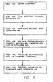
- a user in a first step 100, first obtains a substrate on which to apply profiled insulation 10.
- the substrate onto which profiled insulation 10 is placed is copper wires 16 as shown in twisted pair 14 in Fig. 2 and as discussed in detail above.
- a similar process may be used to form profiled jacket 32 from Fig. 5 , where the substrate would be all of the internal components of cable 30.
- the substrate, wire 16 is selected, it is fed through hollow cavity 53 of extrusion tip 52 and pulled out of the front opening of extrusion die 50 at step 102.
- the heated molten polymer, such as FEP is introduced into polymer chamber 54 of extrusion die 50.
- step 106 as the polymer proceeds to the front of extrusion die 50 and exits out of the front end, the polymer moves around air chambers 56 (as well as vertical fins 58) causing a corresponding number of cavities 12 to form in the polymer 12.
- air pressure is introduced or removed by air-pressure device 59 via vertical fins 58 and vents 57, further increasing or decreasing air pressure within cavities 12.
- vertical fins 58 simply allow ambient air around extrusion die 50 via vents 57 to enter air chambers 50 and consequently enter cavities 12 in the polymer.
- pressure is introduced via air pressure device 59, preferably either Air, Nitrogen or Helium are used, however, any useful and non-reactive gas may be used as desired.
- air pressure device 59 in use for example in creating cavities 12 in insulation 10 of Fig, 1B , a pressure of 13 789 Pa (2 psi), with the volume of Nitrogen at 728 cc/min produces 10 holes at 0,0762 mm (0.003") diameter each, at a tooling draw down ratio of 127:1 and with a calculated effective dielectric of 1.930.
- Changing the volume of Nitrogen to 612 cc/min at a similar pressure of 13 789 Pa (2 psi) produces holes in the insulation at a 0,0635 mm (0.0025"), with a tooling ratio of 127:1, yielding an effective dielectric of 1.978.
- This step 108 provides a distinct advantage over the prior art.
- the air pressure can be dynamically changed during the extrusion process thereby varying the effective dielectric constant of profiled insulation 10.
- This dynamic changing of air pressure by pressure device 59 during an extrusion eliminates the costly shut down and re-tooling of an extrusion apparatus, allowing the dielectric constant of the resultant profiled insulation to be adjusted/corrected on the fly.
- both wires 16 (substrate) as well as the polymer exit the front of extrusion die 50.
- tools of extrusion die 50 are larger than the finished profiled insulation 10 obtained by the process.
- the ratio of the size of the extrusion die openings to the size of the final profiled insulation product 10 is known as the draw down ratio.
- This size differential allows the molten polymer to "draw down” onto wires 16 at a distance away from the front exit of extrusion die 50.
- the drawn down ration DDR is 120 but may vary between 50 to 200.
- the DDR is a ratio of the cross-sectional area of the insulation compared to the cross-sectional area of the polymer as it exits the tooling.
Landscapes
- Engineering & Computer Science (AREA)
- Manufacturing & Machinery (AREA)
- Extrusion Moulding Of Plastics Or The Like (AREA)
Claims (14)
- Vorrichtung zum Herstellen einer profilierten Isolierung (10), wobei die Vorrichtung umfasst:eine Extrusionsdüse (50), wobei die Extrusionsdüse (50) eine Extrusionsspitze (52) und eine die Extrusionsspitze (52) umgebende Polymerkammer (54) aufweist;wobei die Polymerkammer (54) zumindest eine Luftkammer (56) darin aufweist, wobei die Luftkammer (56) von einer vertikalen Lamelle (58), die sich von der Mitte der Extrusionsdüse (50) über Entlüftungsstutzen (57) radial nach außen erstreckt, an ihrem Platz gehalten und mit der Außenseite der Extrusionsdüse (50) verbunden wird;wobei, wenn geschmolzenes Polymer durch die Polymerkammer (54) um die Luftkammer (56) herum fließt, eine Öffnung in das Polymer eingebracht wird, so dass die profilierte Isolierung gebildet wird, wenn das Polymer die Extrusionsdüse verlässt, die einen Längshohlraum (12, 33) darin aufweist, der dem Standort der von der zumindest einen Luftkammer (56) gebildeten Öffnung entspricht.
- Vorrichtung nach Anspruch 1, wobei die Extrusionsdüse (50) eines von 6, 10 und 17 Luftkammern innerhalb der Polymerkammer aufweist.
- Vorrichtung nach Anspruch 1, wobei die Luftkammern (56) kreisförmig oder trapezförmig sind.
- Vorrichtung nach Anspruch 1, wobei die Luftkammern (56) einen Durchmesser von im Wesentlichen 0,89 mm (0,035 Zoll) aufweisen.
- Vorrichtung nach Anspruch 4, wobei die Luftkammern (56) in der Polymerkammer 12,7 mm (0,5 Zoll) vom offenen Ende der Extrusionsspitze enden.
- Vorrichtung nach Anspruch 1, wobei die Lamellen (58) am Verbindungspunkt mit der Luftkammer einen Durchmesser von im Wesentlichen 0,762 mm (0,030 Zoll) aufweisen.
- Vorrichtung nach Anspruch 1, ferner umfassend eine Luftdruckvorrichtung, die mit den Lamellen (58) verbunden und eingerichtet ist, um Druckgas in die Hohlräume (12, 33) der profilierten Isolierung (10) zuzuführen.
- Verfahren zum Herstellen einer profilierten Isolierung (10) über einen Extrusionsprozess, wobei das Verfahren die folgenden Schritte umfasst:Bereitstellen eines geschmolzenen Polymers, wobei das Polymer in eine Isolierung in einer Polymerkammer (54) innerhalb einer Extrusionsdüse (50) gebildet wird, wobei die Extrusionsdüse (50) eine Extrusionsspitze (52) aufweist;wobei das Polymer um eine oder mehrere Luftkammern (56) in der Polymerkammer (54) fließt, wobei die Luftkammer (56) von einer vertikalen Lamelle (58), die sich von der Mitte der Extrusionsdüse (50) über Entlüftungsstutzen (57) radial nach außen erstreckt, an ihrem Platz gehalten und mit der Außenseite der Extrusionsdüse (50) verbunden wird; undBilden einer profilierten Isolierung (10) mit Längshohlräumen (12, 33), die dem Standort der Luftkammern (56) entsprechen.
- Verfahren nach Anspruch 8, ferner umfassend den Schritt des Einbringens eines Überdrucks in die Luftkammern (56) über eine Luftdruckvorrichtung, die mit der Lamelle (58) verbunden ist, die wiederum mit den Luftkammern verbunden ist.
- Verfahren nach Anspruch 9, wobei der Überdruck unter Verwendung eines von Druckluft, Stickstoff und Helium erhalten wird.
- Verfahren nach Anspruch 9, wobei der Überdruck bei im Wesentlichen 13789 Pa (2 psi) eingebracht wird.
- Verfahren nach Anspruch 9, wobei das Gas bei entweder im Wesentlichen 728 cm3/min and 612 cm3/min eingebracht wird.
- Verfahren nach Anspruch 9, wobei der Überdruck während des Extrusionsprozesses dynamisch verändert wird, so dass eingebrachte Änderungen im Druck und Volumen des Gases den Durchmesser der Hohlräume in der profilierten Isolierung dynamisch verändern.
- Verfahren nach Anspruch 8, ferner umfassend den Schritt des Erstickens der Luftkammer, wodurch ein Vakuum gebildet wird, aus dem eine Isolierung entsteht, die die Spitze der Extrusionsdüse verlässt, wobei eine profilierte Isolierung mit kollabierten Hohlräumen gebildet wird, die dem Standort der Luftkammern entsprechen.
Applications Claiming Priority (1)
| Application Number | Priority Date | Filing Date | Title |
|---|---|---|---|
| US11/260,871 US7993568B2 (en) | 2005-10-27 | 2005-10-27 | Profiled insulation LAN cables |
Publications (2)
| Publication Number | Publication Date |
|---|---|
| EP1783787A1 EP1783787A1 (de) | 2007-05-09 |
| EP1783787B1 true EP1783787B1 (de) | 2013-03-06 |
Family
ID=37663333
Family Applications (1)
| Application Number | Title | Priority Date | Filing Date |
|---|---|---|---|
| EP06301077A Not-in-force EP1783787B1 (de) | 2005-10-27 | 2006-10-23 | Lan Kabel mit Profilierter Isolation |
Country Status (4)
| Country | Link |
|---|---|
| US (1) | US7993568B2 (de) |
| EP (1) | EP1783787B1 (de) |
| KR (1) | KR101270732B1 (de) |
| CN (1) | CN101093740B (de) |
Families Citing this family (26)
| Publication number | Priority date | Publication date | Assignee | Title |
|---|---|---|---|---|
| US7560646B2 (en) | 2007-05-31 | 2009-07-14 | Nexans | Profiled insulation and method for making the same |
| FR2919750B1 (fr) * | 2007-08-02 | 2016-01-08 | Axon Cable Sa | Cable coaxial a faible constante dielectrique, et ses procede et outil de fabrication |
| CN101978433A (zh) * | 2008-03-17 | 2011-02-16 | 纳幕尔杜邦公司 | 抗压导体绝缘材料 |
| US20090233052A1 (en) * | 2008-03-17 | 2009-09-17 | E.I. Du Pont De Nemours And Company | Conductors Having Polymer Insulation On Irregular Surface |
| US7795539B2 (en) * | 2008-03-17 | 2010-09-14 | E. I. Du Pont De Nemours And Company | Crush resistant conductor insulation |
| CA2724528C (en) * | 2008-07-03 | 2017-03-28 | Adc Telecommunications, Inc. | Telecommunications wire having a channeled dielectric insulator and methods for manufacturing the same |
| JP5421565B2 (ja) * | 2008-09-24 | 2014-02-19 | 住友電気工業株式会社 | 同軸ケーブル |
| US8735726B2 (en) * | 2009-01-14 | 2014-05-27 | General Cable Technologies Corporation | Jacket for data cable |
| US20100276178A1 (en) * | 2009-04-29 | 2010-11-04 | Joshua Keller | Profiled insulation and method for making the same |
| US9129727B2 (en) * | 2009-05-04 | 2015-09-08 | Panduit Corp. | Communication cable with embossed tape having encapsulated gas |
| KR20120027086A (ko) * | 2009-05-29 | 2012-03-21 | 스미토모 덴키 고교 가부시키가이샤 | 전선의 제조 방법 |
| US9368258B2 (en) | 2011-11-23 | 2016-06-14 | Nexans | Forward twisted profiled insulation for LAN cables |
| CN102568664A (zh) * | 2012-02-22 | 2012-07-11 | 江苏亨鑫科技有限公司 | 低损耗耐高温电缆 |
| US9242419B2 (en) * | 2012-05-09 | 2016-01-26 | Milliken & Company | Divided conduit extrusion die and method |
| CN104319027B (zh) * | 2014-11-13 | 2017-09-22 | 东莞市傲森电子科技有限公司 | 一种高温极细线发泡铁氟龙的藕状押出方法 |
| CN107258004A (zh) * | 2014-12-19 | 2017-10-17 | 陶氏环球技术有限责任公司 | 具有经设计的微观结构的电缆护套以及制备具有经设计的微观结构的电缆护套的方法 |
| BR112017016756B1 (pt) * | 2015-02-20 | 2022-11-01 | Dow Global Technologies Llc | Condutor revestido |
| JP6152867B2 (ja) * | 2015-04-06 | 2017-06-28 | 横浜ゴム株式会社 | ゴム押出部材の製造方法及び製造装置 |
| EP3357073B1 (de) * | 2015-09-28 | 2020-12-23 | Dow Global Technologies LLC | Abziehbarer kabelmantel mit designten mikrostrukturen sowie verfahren zur herstellung von abziehbaren kabelmänteln mit designten mikrostrukturen |
| EP3357072B1 (de) * | 2015-09-28 | 2020-12-09 | Dow Global Technologies LLC | Abziehbarer kabelmantel mit designten mikrostrukturen sowie verfahren zur herstellung von abziehbaren kabelmänteln mit designten mikrostrukturen |
| CN108028102B (zh) * | 2015-09-28 | 2022-07-22 | 陶氏环球技术有限责任公司 | 具有所设计的微观结构的可剥离电缆护套和用于制备具有所设计的微观结构的可剥离电缆护套的方法 |
| DE102016224106A1 (de) * | 2016-12-05 | 2018-06-07 | Leoni Kabel Gmbh | Hochstromkabel und Stromversorgungssystem mit Hochstromkabel |
| US10784014B1 (en) * | 2019-06-20 | 2020-09-22 | Superior Essex International LP | Cables with foamed insulation suitable for air-blown installation |
| CN115458222A (zh) * | 2021-05-21 | 2022-12-09 | 泰科电子(上海)有限公司 | 带状电缆 |
| US20250157700A1 (en) * | 2023-11-14 | 2025-05-15 | Leviton Manufacturing Co., Inc. | Layered profile insulation |
| CN121726141A (zh) * | 2024-09-24 | 2026-03-24 | 华为技术有限公司 | 电缆 |
Family Cites Families (10)
| Publication number | Priority date | Publication date | Assignee | Title |
|---|---|---|---|---|
| US3274315A (en) * | 1963-02-25 | 1966-09-20 | Tokan Kogyo Co Ltd | Process for unitized construction of synthetic resin board or cylinder |
| US3299686A (en) * | 1964-01-13 | 1967-01-24 | Northern Electric Co | Strand extruder |
| DE1735017C3 (de) * | 1966-02-07 | 1979-04-05 | Francesco Dr.-Ing. Mailand Steffenini (Italien) | Einteilige Wickelhülse aus Kunststoff, insbesondere zur Aufnahme von Garnwicklungen |
| US3771934A (en) * | 1969-02-18 | 1973-11-13 | Int Standard Electric Corp | Apparatus for extending water-blocked cartwheel cable |
| FR2141599A1 (de) | 1971-06-18 | 1973-01-26 | Cotexunion | |
| US4655987A (en) * | 1982-10-12 | 1987-04-07 | Guillermo Zertuche | Method and apparatus for extruding tubular articles having several conduits |
| US5063018A (en) * | 1990-06-04 | 1991-11-05 | Cordis Corporation | Extrusion method |
| FR2747832B1 (fr) * | 1996-04-23 | 1998-05-22 | Filotex Sa | Procede et dispositif de fabrication d'une gaine aeree en un materiau isolant autour d'un conducteur, et cable coaxial muni d'une telle gaine |
| US7214880B2 (en) * | 2002-09-24 | 2007-05-08 | Adc Incorporated | Communication wire |
| US7163388B2 (en) * | 2004-05-19 | 2007-01-16 | Cangen Holdings, Inc. | Method and apparatus for incorporating lumens into the wall of a tubular extrusion |
-
2005
- 2005-10-27 US US11/260,871 patent/US7993568B2/en not_active Expired - Lifetime
-
2006
- 2006-10-23 EP EP06301077A patent/EP1783787B1/de not_active Not-in-force
- 2006-10-26 KR KR1020060104538A patent/KR101270732B1/ko not_active Expired - Fee Related
- 2006-10-27 CN CN2006101719277A patent/CN101093740B/zh not_active Expired - Fee Related
Also Published As
| Publication number | Publication date |
|---|---|
| CN101093740A (zh) | 2007-12-26 |
| US20070098940A1 (en) | 2007-05-03 |
| US7993568B2 (en) | 2011-08-09 |
| KR101270732B1 (ko) | 2013-06-03 |
| EP1783787A1 (de) | 2007-05-09 |
| KR20070045962A (ko) | 2007-05-02 |
| CN101093740B (zh) | 2013-02-06 |
Similar Documents
| Publication | Publication Date | Title |
|---|---|---|
| EP1783787B1 (de) | Lan Kabel mit Profilierter Isolation | |
| CA1154216A (en) | Foamed perfluorocarbon resin compositions | |
| CN101930806B (zh) | 树脂组合物及高频同轴电缆 | |
| US6231919B1 (en) | Method of making conductor insulated with foamed fluoropolymer | |
| CN211237751U (zh) | 具有介电泡沫的电缆 | |
| EP1998341B1 (de) | Verbesserte profilierte Isolierung und Herstellungsverfahren dafür | |
| EP2065155B1 (de) | Schäumende Polymerzusammensetzung mit hoher Verarbeitungstemperatur | |
| EP1942134A1 (de) | Schäumende Polymerzusammensetzung mit hoher Verarbeitungstemperatur | |
| EP2208750B1 (de) | Übertragungsleitung enthaltend einen dielektrischen microzellularen Schaum | |
| US6124770A (en) | Expandable resin composition | |
| US20140367143A1 (en) | Coaxial cable | |
| CN102738549B (zh) | 高频同轴电缆 | |
| US2835927A (en) | Methods of producing cellular plastics | |
| CN117476290B (zh) | 射频同轴电缆的制造方法、射频同轴电缆及制造装置 | |
| CN1301842C (zh) | 制造具有泡沫绝缘的同轴导线的设备与方法 | |
| EP3548252B1 (de) | Mikrokapillare drahtbeschichtungsdüsenmontage | |
| JP2011228064A (ja) | 高周波同軸ケーブルの製造方法及び高周波同軸ケーブル並びに押出装置 | |
| EP1935931A1 (de) | Schäumende Polymerzusammensetzung mit hoher Verarbeitungstemperatur | |
| Marvian et al. | Extrusion foam coating of coaxial cables using chemical blowing agent | |
| JPH03275737A (ja) | 発泡ポリエーテルエーテルケトン絶縁電線の製造方法 | |
| JPH03233815A (ja) | 発泡絶縁電線の製造方法 | |
| DE2521526A1 (de) | Verfahren zur herstellung von mit geschaeumtem pvc isolierten adern fuer elektrische kabel | |
| JPH03272516A (ja) | 発泡ポリエーテルイミド絶縁電線の製造方法 | |
| Marvian et al. | Extrusion foam coating of coaxial cables using butane as physical blowing agent | |
| JPS6119412B2 (de) |
Legal Events
| Date | Code | Title | Description |
|---|---|---|---|
| PUAI | Public reference made under article 153(3) epc to a published international application that has entered the european phase |
Free format text: ORIGINAL CODE: 0009012 |
|
| AK | Designated contracting states |
Kind code of ref document: A1 Designated state(s): AT BE BG CH CY CZ DE DK EE ES FI FR GB GR HU IE IS IT LI LT LU LV MC NL PL PT RO SE SI SK TR |
|
| AX | Request for extension of the european patent |
Extension state: AL BA HR MK YU |
|
| 17P | Request for examination filed |
Effective date: 20071109 |
|
| AKX | Designation fees paid |
Designated state(s): AT BE BG CH CY CZ DE DK EE ES FI FR GB GR HU IE IS IT LI LT LU LV MC NL PL PT RO SE SI SK TR |
|
| 17Q | First examination report despatched |
Effective date: 20090929 |
|
| RAP1 | Party data changed (applicant data changed or rights of an application transferred) |
Owner name: NEXANS |
|
| GRAP | Despatch of communication of intention to grant a patent |
Free format text: ORIGINAL CODE: EPIDOSNIGR1 |
|
| GRAS | Grant fee paid |
Free format text: ORIGINAL CODE: EPIDOSNIGR3 |
|
| GRAA | (expected) grant |
Free format text: ORIGINAL CODE: 0009210 |
|
| AK | Designated contracting states |
Kind code of ref document: B1 Designated state(s): AT BE BG CH CY CZ DE DK EE ES FI FR GB GR HU IE IS IT LI LT LU LV MC NL PL PT RO SE SI SK TR |
|
| REG | Reference to a national code |
Ref country code: GB Ref legal event code: FG4D |
|
| REG | Reference to a national code |
Ref country code: CH Ref legal event code: EP Ref country code: AT Ref legal event code: REF Ref document number: 600033 Country of ref document: AT Kind code of ref document: T Effective date: 20130315 |
|
| REG | Reference to a national code |
Ref country code: IE Ref legal event code: FG4D |
|
| REG | Reference to a national code |
Ref country code: DE Ref legal event code: R096 Ref document number: 602006034887 Country of ref document: DE Effective date: 20130502 |
|
| REG | Reference to a national code |
Ref country code: AT Ref legal event code: MK05 Ref document number: 600033 Country of ref document: AT Kind code of ref document: T Effective date: 20130306 |
|
| PG25 | Lapsed in a contracting state [announced via postgrant information from national office to epo] |
Ref country code: LT Free format text: LAPSE BECAUSE OF FAILURE TO SUBMIT A TRANSLATION OF THE DESCRIPTION OR TO PAY THE FEE WITHIN THE PRESCRIBED TIME-LIMIT Effective date: 20130306 Ref country code: AT Free format text: LAPSE BECAUSE OF FAILURE TO SUBMIT A TRANSLATION OF THE DESCRIPTION OR TO PAY THE FEE WITHIN THE PRESCRIBED TIME-LIMIT Effective date: 20130306 Ref country code: SE Free format text: LAPSE BECAUSE OF FAILURE TO SUBMIT A TRANSLATION OF THE DESCRIPTION OR TO PAY THE FEE WITHIN THE PRESCRIBED TIME-LIMIT Effective date: 20130306 Ref country code: ES Free format text: LAPSE BECAUSE OF FAILURE TO SUBMIT A TRANSLATION OF THE DESCRIPTION OR TO PAY THE FEE WITHIN THE PRESCRIBED TIME-LIMIT Effective date: 20130617 Ref country code: BG Free format text: LAPSE BECAUSE OF FAILURE TO SUBMIT A TRANSLATION OF THE DESCRIPTION OR TO PAY THE FEE WITHIN THE PRESCRIBED TIME-LIMIT Effective date: 20130606 |
|
| REG | Reference to a national code |
Ref country code: NL Ref legal event code: VDEP Effective date: 20130306 |
|
| REG | Reference to a national code |
Ref country code: LT Ref legal event code: MG4D |
|
| PG25 | Lapsed in a contracting state [announced via postgrant information from national office to epo] |
Ref country code: FI Free format text: LAPSE BECAUSE OF FAILURE TO SUBMIT A TRANSLATION OF THE DESCRIPTION OR TO PAY THE FEE WITHIN THE PRESCRIBED TIME-LIMIT Effective date: 20130306 Ref country code: SI Free format text: LAPSE BECAUSE OF FAILURE TO SUBMIT A TRANSLATION OF THE DESCRIPTION OR TO PAY THE FEE WITHIN THE PRESCRIBED TIME-LIMIT Effective date: 20130306 Ref country code: GR Free format text: LAPSE BECAUSE OF FAILURE TO SUBMIT A TRANSLATION OF THE DESCRIPTION OR TO PAY THE FEE WITHIN THE PRESCRIBED TIME-LIMIT Effective date: 20130607 Ref country code: LV Free format text: LAPSE BECAUSE OF FAILURE TO SUBMIT A TRANSLATION OF THE DESCRIPTION OR TO PAY THE FEE WITHIN THE PRESCRIBED TIME-LIMIT Effective date: 20130306 |
|
| PG25 | Lapsed in a contracting state [announced via postgrant information from national office to epo] |
Ref country code: IS Free format text: LAPSE BECAUSE OF FAILURE TO SUBMIT A TRANSLATION OF THE DESCRIPTION OR TO PAY THE FEE WITHIN THE PRESCRIBED TIME-LIMIT Effective date: 20130706 Ref country code: PT Free format text: LAPSE BECAUSE OF FAILURE TO SUBMIT A TRANSLATION OF THE DESCRIPTION OR TO PAY THE FEE WITHIN THE PRESCRIBED TIME-LIMIT Effective date: 20130708 Ref country code: NL Free format text: LAPSE BECAUSE OF FAILURE TO SUBMIT A TRANSLATION OF THE DESCRIPTION OR TO PAY THE FEE WITHIN THE PRESCRIBED TIME-LIMIT Effective date: 20130306 Ref country code: CZ Free format text: LAPSE BECAUSE OF FAILURE TO SUBMIT A TRANSLATION OF THE DESCRIPTION OR TO PAY THE FEE WITHIN THE PRESCRIBED TIME-LIMIT Effective date: 20130306 Ref country code: RO Free format text: LAPSE BECAUSE OF FAILURE TO SUBMIT A TRANSLATION OF THE DESCRIPTION OR TO PAY THE FEE WITHIN THE PRESCRIBED TIME-LIMIT Effective date: 20130306 Ref country code: EE Free format text: LAPSE BECAUSE OF FAILURE TO SUBMIT A TRANSLATION OF THE DESCRIPTION OR TO PAY THE FEE WITHIN THE PRESCRIBED TIME-LIMIT Effective date: 20130306 Ref country code: SK Free format text: LAPSE BECAUSE OF FAILURE TO SUBMIT A TRANSLATION OF THE DESCRIPTION OR TO PAY THE FEE WITHIN THE PRESCRIBED TIME-LIMIT Effective date: 20130306 |
|
| PG25 | Lapsed in a contracting state [announced via postgrant information from national office to epo] |
Ref country code: PL Free format text: LAPSE BECAUSE OF FAILURE TO SUBMIT A TRANSLATION OF THE DESCRIPTION OR TO PAY THE FEE WITHIN THE PRESCRIBED TIME-LIMIT Effective date: 20130306 Ref country code: CY Free format text: LAPSE BECAUSE OF FAILURE TO SUBMIT A TRANSLATION OF THE DESCRIPTION OR TO PAY THE FEE WITHIN THE PRESCRIBED TIME-LIMIT Effective date: 20130306 |
|
| PLBE | No opposition filed within time limit |
Free format text: ORIGINAL CODE: 0009261 |
|
| STAA | Information on the status of an ep patent application or granted ep patent |
Free format text: STATUS: NO OPPOSITION FILED WITHIN TIME LIMIT |
|
| PG25 | Lapsed in a contracting state [announced via postgrant information from national office to epo] |
Ref country code: DK Free format text: LAPSE BECAUSE OF FAILURE TO SUBMIT A TRANSLATION OF THE DESCRIPTION OR TO PAY THE FEE WITHIN THE PRESCRIBED TIME-LIMIT Effective date: 20130306 |
|
| 26N | No opposition filed |
Effective date: 20131209 |
|
| PG25 | Lapsed in a contracting state [announced via postgrant information from national office to epo] |
Ref country code: IT Free format text: LAPSE BECAUSE OF FAILURE TO SUBMIT A TRANSLATION OF THE DESCRIPTION OR TO PAY THE FEE WITHIN THE PRESCRIBED TIME-LIMIT Effective date: 20130306 |
|
| REG | Reference to a national code |
Ref country code: DE Ref legal event code: R097 Ref document number: 602006034887 Country of ref document: DE Effective date: 20131209 |
|
| PG25 | Lapsed in a contracting state [announced via postgrant information from national office to epo] |
Ref country code: MC Free format text: LAPSE BECAUSE OF FAILURE TO SUBMIT A TRANSLATION OF THE DESCRIPTION OR TO PAY THE FEE WITHIN THE PRESCRIBED TIME-LIMIT Effective date: 20130306 |
|
| REG | Reference to a national code |
Ref country code: CH Ref legal event code: PL |
|
| GBPC | Gb: european patent ceased through non-payment of renewal fee |
Effective date: 20131023 |
|
| REG | Reference to a national code |
Ref country code: IE Ref legal event code: MM4A |
|
| PG25 | Lapsed in a contracting state [announced via postgrant information from national office to epo] |
Ref country code: GB Free format text: LAPSE BECAUSE OF NON-PAYMENT OF DUE FEES Effective date: 20131023 Ref country code: LI Free format text: LAPSE BECAUSE OF NON-PAYMENT OF DUE FEES Effective date: 20131031 Ref country code: CH Free format text: LAPSE BECAUSE OF NON-PAYMENT OF DUE FEES Effective date: 20131031 |
|
| PG25 | Lapsed in a contracting state [announced via postgrant information from national office to epo] |
Ref country code: IE Free format text: LAPSE BECAUSE OF NON-PAYMENT OF DUE FEES Effective date: 20131023 |
|
| PG25 | Lapsed in a contracting state [announced via postgrant information from national office to epo] |
Ref country code: LU Free format text: LAPSE BECAUSE OF NON-PAYMENT OF DUE FEES Effective date: 20131023 Ref country code: HU Free format text: LAPSE BECAUSE OF FAILURE TO SUBMIT A TRANSLATION OF THE DESCRIPTION OR TO PAY THE FEE WITHIN THE PRESCRIBED TIME-LIMIT; INVALID AB INITIO Effective date: 20061023 |
|
| REG | Reference to a national code |
Ref country code: FR Ref legal event code: PLFP Year of fee payment: 10 |
|
| REG | Reference to a national code |
Ref country code: FR Ref legal event code: PLFP Year of fee payment: 11 |
|
| REG | Reference to a national code |
Ref country code: FR Ref legal event code: PLFP Year of fee payment: 12 |
|
| REG | Reference to a national code |
Ref country code: FR Ref legal event code: PLFP Year of fee payment: 13 |
|
| PGFP | Annual fee paid to national office [announced via postgrant information from national office to epo] |
Ref country code: DE Payment date: 20181019 Year of fee payment: 13 |
|
| PGFP | Annual fee paid to national office [announced via postgrant information from national office to epo] |
Ref country code: TR Payment date: 20181011 Year of fee payment: 13 Ref country code: BE Payment date: 20181019 Year of fee payment: 13 Ref country code: FR Payment date: 20181022 Year of fee payment: 13 |
|
| REG | Reference to a national code |
Ref country code: DE Ref legal event code: R119 Ref document number: 602006034887 Country of ref document: DE |
|
| PG25 | Lapsed in a contracting state [announced via postgrant information from national office to epo] |
Ref country code: DE Free format text: LAPSE BECAUSE OF NON-PAYMENT OF DUE FEES Effective date: 20200501 |
|
| REG | Reference to a national code |
Ref country code: BE Ref legal event code: MM Effective date: 20191031 |
|
| PG25 | Lapsed in a contracting state [announced via postgrant information from national office to epo] |
Ref country code: BE Free format text: LAPSE BECAUSE OF NON-PAYMENT OF DUE FEES Effective date: 20191031 |
|
| PG25 | Lapsed in a contracting state [announced via postgrant information from national office to epo] |
Ref country code: FR Free format text: LAPSE BECAUSE OF NON-PAYMENT OF DUE FEES Effective date: 20191031 |
|
| PG25 | Lapsed in a contracting state [announced via postgrant information from national office to epo] |
Ref country code: TR Free format text: LAPSE BECAUSE OF NON-PAYMENT OF DUE FEES Effective date: 20191023 |