EP1784248B1 - Dialysesystem - Google Patents
Dialysesystem Download PDFInfo
- Publication number
- EP1784248B1 EP1784248B1 EP05759485.5A EP05759485A EP1784248B1 EP 1784248 B1 EP1784248 B1 EP 1784248B1 EP 05759485 A EP05759485 A EP 05759485A EP 1784248 B1 EP1784248 B1 EP 1784248B1
- Authority
- EP
- European Patent Office
- Prior art keywords
- housing
- exchange resin
- dialysate fluid
- sodium
- meq
- Prior art date
- Legal status (The legal status is an assumption and is not a legal conclusion. Google has not performed a legal analysis and makes no representation as to the accuracy of the status listed.)
- Expired - Lifetime
Links
Images


Classifications
-
- B—PERFORMING OPERATIONS; TRANSPORTING
- B01—PHYSICAL OR CHEMICAL PROCESSES OR APPARATUS IN GENERAL
- B01D—SEPARATION
- B01D61/00—Processes of separation using semi-permeable membranes, e.g. dialysis, osmosis or ultrafiltration; Apparatus, accessories or auxiliary operations specially adapted therefor
- B01D61/24—Dialysis ; Membrane extraction
- B01D61/30—Accessories; Auxiliary operation
-
- A—HUMAN NECESSITIES
- A61—MEDICAL OR VETERINARY SCIENCE; HYGIENE
- A61M—DEVICES FOR INTRODUCING MEDIA INTO, OR ONTO, THE BODY; DEVICES FOR TRANSDUCING BODY MEDIA OR FOR TAKING MEDIA FROM THE BODY; DEVICES FOR PRODUCING OR ENDING SLEEP OR STUPOR
- A61M1/00—Suction or pumping devices for medical purposes; Devices for carrying-off, for treatment of, or for carrying-over, body-liquids; Drainage systems
- A61M1/14—Dialysis systems; Artificial kidneys; Blood oxygenators ; Reciprocating systems for treatment of body fluids, e.g. single needle systems for hemofiltration or pheresis
- A61M1/16—Dialysis systems; Artificial kidneys; Blood oxygenators ; Reciprocating systems for treatment of body fluids, e.g. single needle systems for hemofiltration or pheresis with membranes
-
- A—HUMAN NECESSITIES
- A61—MEDICAL OR VETERINARY SCIENCE; HYGIENE
- A61M—DEVICES FOR INTRODUCING MEDIA INTO, OR ONTO, THE BODY; DEVICES FOR TRANSDUCING BODY MEDIA OR FOR TAKING MEDIA FROM THE BODY; DEVICES FOR PRODUCING OR ENDING SLEEP OR STUPOR
- A61M1/00—Suction or pumping devices for medical purposes; Devices for carrying-off, for treatment of, or for carrying-over, body-liquids; Drainage systems
- A61M1/14—Dialysis systems; Artificial kidneys; Blood oxygenators ; Reciprocating systems for treatment of body fluids, e.g. single needle systems for hemofiltration or pheresis
- A61M1/16—Dialysis systems; Artificial kidneys; Blood oxygenators ; Reciprocating systems for treatment of body fluids, e.g. single needle systems for hemofiltration or pheresis with membranes
- A61M1/1601—Control or regulation
- A61M1/1603—Regulation parameters
- A61M1/1605—Physical characteristics of the dialysate fluid
-
- A—HUMAN NECESSITIES
- A61—MEDICAL OR VETERINARY SCIENCE; HYGIENE
- A61M—DEVICES FOR INTRODUCING MEDIA INTO, OR ONTO, THE BODY; DEVICES FOR TRANSDUCING BODY MEDIA OR FOR TAKING MEDIA FROM THE BODY; DEVICES FOR PRODUCING OR ENDING SLEEP OR STUPOR
- A61M1/00—Suction or pumping devices for medical purposes; Devices for carrying-off, for treatment of, or for carrying-over, body-liquids; Drainage systems
- A61M1/14—Dialysis systems; Artificial kidneys; Blood oxygenators ; Reciprocating systems for treatment of body fluids, e.g. single needle systems for hemofiltration or pheresis
- A61M1/16—Dialysis systems; Artificial kidneys; Blood oxygenators ; Reciprocating systems for treatment of body fluids, e.g. single needle systems for hemofiltration or pheresis with membranes
- A61M1/1694—Dialysis systems; Artificial kidneys; Blood oxygenators ; Reciprocating systems for treatment of body fluids, e.g. single needle systems for hemofiltration or pheresis with membranes with recirculating dialysing liquid
- A61M1/1696—Dialysis systems; Artificial kidneys; Blood oxygenators ; Reciprocating systems for treatment of body fluids, e.g. single needle systems for hemofiltration or pheresis with membranes with recirculating dialysing liquid with dialysate regeneration
-
- A—HUMAN NECESSITIES
- A61—MEDICAL OR VETERINARY SCIENCE; HYGIENE
- A61M—DEVICES FOR INTRODUCING MEDIA INTO, OR ONTO, THE BODY; DEVICES FOR TRANSDUCING BODY MEDIA OR FOR TAKING MEDIA FROM THE BODY; DEVICES FOR PRODUCING OR ENDING SLEEP OR STUPOR
- A61M1/00—Suction or pumping devices for medical purposes; Devices for carrying-off, for treatment of, or for carrying-over, body-liquids; Drainage systems
- A61M1/34—Filtering material out of the blood by passing it through a membrane, i.e. hemofiltration or diafiltration
-
- A—HUMAN NECESSITIES
- A61—MEDICAL OR VETERINARY SCIENCE; HYGIENE
- A61M—DEVICES FOR INTRODUCING MEDIA INTO, OR ONTO, THE BODY; DEVICES FOR TRANSDUCING BODY MEDIA OR FOR TAKING MEDIA FROM THE BODY; DEVICES FOR PRODUCING OR ENDING SLEEP OR STUPOR
- A61M1/00—Suction or pumping devices for medical purposes; Devices for carrying-off, for treatment of, or for carrying-over, body-liquids; Drainage systems
- A61M1/34—Filtering material out of the blood by passing it through a membrane, i.e. hemofiltration or diafiltration
- A61M1/3403—Regulation parameters
-
- A—HUMAN NECESSITIES
- A61—MEDICAL OR VETERINARY SCIENCE; HYGIENE
- A61M—DEVICES FOR INTRODUCING MEDIA INTO, OR ONTO, THE BODY; DEVICES FOR TRANSDUCING BODY MEDIA OR FOR TAKING MEDIA FROM THE BODY; DEVICES FOR PRODUCING OR ENDING SLEEP OR STUPOR
- A61M1/00—Suction or pumping devices for medical purposes; Devices for carrying-off, for treatment of, or for carrying-over, body-liquids; Drainage systems
- A61M1/34—Filtering material out of the blood by passing it through a membrane, i.e. hemofiltration or diafiltration
- A61M1/3403—Regulation parameters
- A61M1/341—Regulation parameters by measuring the filtrate rate or volume
-
- A—HUMAN NECESSITIES
- A61—MEDICAL OR VETERINARY SCIENCE; HYGIENE
- A61M—DEVICES FOR INTRODUCING MEDIA INTO, OR ONTO, THE BODY; DEVICES FOR TRANSDUCING BODY MEDIA OR FOR TAKING MEDIA FROM THE BODY; DEVICES FOR PRODUCING OR ENDING SLEEP OR STUPOR
- A61M2205/00—General characteristics of the apparatus
- A61M2205/33—Controlling, regulating or measuring
- A61M2205/3331—Pressure; Flow
-
- A—HUMAN NECESSITIES
- A61—MEDICAL OR VETERINARY SCIENCE; HYGIENE
- A61M—DEVICES FOR INTRODUCING MEDIA INTO, OR ONTO, THE BODY; DEVICES FOR TRANSDUCING BODY MEDIA OR FOR TAKING MEDIA FROM THE BODY; DEVICES FOR PRODUCING OR ENDING SLEEP OR STUPOR
- A61M2205/00—General characteristics of the apparatus
- A61M2205/33—Controlling, regulating or measuring
- A61M2205/3368—Temperature
Definitions
- a dialysis system typically includes a hydraulic system for circulating blood, a hydraulic system for circulating dialysate fluid, and a semi-permeable membrane.
- the blood system and the dialysate fluid system have fluid flow paths that extend past the membrane on opposite sides of the membrane. Urea and other blood components, but not blood cells, travel across the membrane from the blood side to the dialysate side as the blood and dialysate fluid both flow past the membrane.
- US 2003/105424 (A1 ) describes methods and devices for providing dialysis treatment.
- the device includes a resin bed including zirconium phosphate, zirconium oxide, and urease.
- dialysate fluid which is water infused with minerals and other essential blood components, is continually directed to flow past a membrane along a flow path extending from a source to a waste receptacle.
- This type of continuous flow may require hundreds of liters of dialysate fluid.
- More current dialysis systems recycle the exposed dialysate fluid rather than send it to a waste receptacle.
- Dialysis systems that recycle dialysate fluid have a dialysate fluid volume on the order of 6-1 0 liters.
- urea and other blood waste compounds In order to recycle dialysate fluid, urea and other blood waste compounds must be removed before the fluid is again passed by the membrane.
- One way to accomplish the removal of urea is to expose the urea to urease, which breaks the urea molecules down into ammonium ions and carbonate.
- the ammonium ions which are toxic and should not be exposed to the membrane, can be bound, for example, by zirconium phosphate.
- zirconium phosphate acts as an ion exchanger and exchanges ammonium ions for sodium ions.
- the 6-10 liter systems have the capacity to dilute rising sodium ion levels such that the sodium ion concentration does not reach physiologically unacceptable levels.
- These 6-10 liter systems have the added benefit of being transportable relative to continuous flow type systems that require a source of high purity water used to make dialysate fluid in high volumes. For example, with the proper training and supervision, 6-10 liter systems can be easily adapted for use in a home environment without extensive equipment installation or home modification.
- Dialysis is often required because a patient's renal function is reduced, which means, in part, that the patient's ability to remove water from the blood is similarly reduced.
- the total hydraulic fluid volume is expandable. Because the total volume is expandable, water can be removed from the patient into the dialysate system during dialysis. Water transport can be accomplished by creating a pressure differential between the blood side and the dialysate side such that water will flow from the blood side across the membrane to the dialysate side in a controlled manner.
- a dialysate fluid circulation apparatus as claimed includes a dialyzer, a first housing and a second housing.
- the first housing contains material capable of releasing sodium into dialysate fluid flowing through the first housing.
- the second housing contains material capable of binding sodium ions from dialysate fluid flowing through the second housing.
- Hydraulic conduit sections are configured to extend between the dialyzer, the first housing, and the second housing to connect the dialyzer with the housings in a primary flow path for dialysate fluid to flow from the dialyzer to the first housing, from the first housing to the second housing, and from the second housing back to the dialyzer.
- the hydraulic conduit sections are further configured to define a bypass flow path for dialysate fluid to bypass the second housing by flowing from the first housing back to the dialyzer.
- a fluid flow regulator is operative to control the flows of dialysate fluid along the primary and bypass flow paths.
- a controller actuates the regulator in response to input from a meter that is operative to indicate the sodium ion concentration in the dialysate fluid emerging from the first housing.
- an apparatus as claimed is configured for use with a dialysate fluid system that includes material capable of releasing sodium into dialysate fluid flowing in the system.
- the apparatus comprises a housing containing material capable of binding sodium ions from dialysate fluid flowing through the housing.
- a method as claimed includes the steps of passing dialysate fluid through a dialyzer, conveying the dialysate fluid from the dialyzer to a first housing containing material that releases sodium into the dialysate fluid, and passing the dialysate fluid through the material in the first housing.
- the method further includes the steps of conveying the dialysate fluid from the first housing to a second housing containing material that binds sodium ions from the dialysate fluid, passing the dialysate fluid through the material in the second housing, and conveying the dialysate fluid from the second housing back to the dialyzer.
- the method includes the additional steps of measuring sodium ion concentration in the dialysate fluid emerging from the first housing, and directing a portion of the dialysate fluid to bypass the second housing if the measured sodium ion concentration is not greater than a predetermined level.
- the dialysis systems shown schematically in the drawings have parts that are examples of the elements recited in the apparatus claims, and can be operated in steps that are examples of the elements recited in the method claims.
- the illustrated systems thus include examples of how a person of ordinary skill in the art can make and use the claimed invention.
- an example of a dialysis system 10 includes a pair of distinct hydraulic systems 12 and 14.
- the first hydraulic system 12 contains dialysate fluid.
- a first pump 16 drives dialysate fluid through the dialysate fluid system 12.
- a second pump 18 drives blood through the blood system 14.
- the dialysate fluid system 12 and the blood system 14 overlap at a dialyzer 20, but are otherwise separate from each other. Impurities, including urea, are drawn out of the blood and into the dialysate fluid as the blood and dialysate fluid both flow through the dialyzer 20.
- the dialysate fluid system 12 further includes a first housing 30 and a second housing 32.
- the first housing 30 contains material 34 that decomposes urea from the dialysate fluid flowing through the first housing 30. The decomposition of urea may produce undesirable amounts of sodium.
- the second housing 32 contains material that binds sodium ions from the dialysate fluid flowing through the second housing 32.
- a first conduit 40 extends from the dialyzer 20 to the first housing 30.
- a second conduit 42 extends from the first housing 30 to the second housing 32.
- a third conduit 44 extends from the second housing 32 back to the dialyzer 20.
- the first, second and third conduits 40, 42 and 44 complete a primary flow path along which the dialysate fluid can circulate through the system 12 in a clockwise direction, as viewed in Fig. 1 under the influence of the pump 16.
- the primary flow path includes the dialyzer 20, the first conduit 40, the first housing 30, the second conduit 42, the second housing 32, and the third conduit 44.
- a fourth conduit 46 bypasses the second housing 32.
- This provides a bypass flow path that differs from the primary flow path by omitting the second housing 32.
- the bypass flow path thus includes the dialyzer 20, the first conduit 40, the first housing 30, a portion of the second conduit 42, the fourth conduit 46, and a portion of the third conduit 44.
- a bypass flow regulator 50 controls the flow of dialysate fluid through the fourth conduit 46.
- the regulator 50 could be a simple clamp or an on/off valve, but preferably is a valve that is shiftable between a closed condition and a range of open conditions.
- the dialysate fluid system 12 includes a bubble remover 54 and an infusate reservoir 56.
- the bubble remover 54 is operative to remove gas bubbles from the dialysate fluid.
- the infusate reservoir 56 has a pump 58 for delivering infusate to the system 12.
- the infusate is a solution containing minerals and other blood components that might need to be added or replenished in the dialysate fluid.
- the dialyzer 20 is a known device including a housing 60 containing a semi-permeable membrane 62.
- the membrane 62 is disposed between the blood system 14 and the dialysate fluid system 12 such that blood flows in one direction through the housing 60 along the blood side 64 of the membrane 62, and dialysate fluid flows in the opposite direction through the housing 60 on the dialysate side 66 of the membrane 62.
- Urea and other blood impurities are small enough to pass through the membrane 62 from the blood side 64 to the dialysate side 66, but blood cells and other blood components are too large to pass through the membrane 62 and are retained in the blood.
- the concentration gradient for each impurity between the blood side 64 and the dialysate side 66 is the concentration gradient for each impurity between the blood side 64 and the dialysate side 66. If the concentration of an impurity on the blood side 64 is higher than the concentration of the impurity on the dialysate side 66, the impurity will diffuse across the membrane 62 in order to equalize the concentration.
- a pressure differential across the membrane 62 Another factor affecting the diffusion of blood impurities across the membrane 62 is a pressure differential across the membrane 62. If the hydraulic fluid pressure is higher on one side of the membrane 62, fluid will flow across the membrane from the higher pressure side to the lower pressure side in order to equalize the pressure across the membrane 62. Fluid flow across the membrane 62 due to pressure differences is not selective in terms of the components flowing across the membrane. Therefore, water molecules, minerals, and other smaller blood components will flow across the membrane 62 under the influence of a sufficient pressure gradient.
- a pressure-driven flow across a membrane from the blood side to the dialysate side is known as ultrafiltration.
- the first housing 30 downstream of the dialyzer 20 preferably is a sorbent-type cartridge containing material 34 that decomposes urea and releases sodium.
- Sorbent cartridges are well known.
- a typical sorbent cartridge contains several layers of materials including, for example, one or more layers of activated carbon, urease, zirconium phosphate, and/or zirconium oxide.
- urease breaks urea down into ammonium and carbonate.
- the zirconium phosphate layer, or a similar material binds the ammonium in exchange for sodium ions.
- the different layers of the sorbent cartridge will, of course, bind other compounds, minerals, and ions as well. Some of these other compounds, minerals, and ions may also cause sodium to be released.
- the combination of these materials allows water suitable for drinking to be charged into the system for use as dialysate fluid.
- the second housing 32 downstream of the dialyzer 20 contains the material 36 that will bind sodium ions.
- One type of compatible material may release protons or some other physiologically harmless or less harmful counter ion in exchange for sodium ions as the sodium ions are adsorbed. Such materials will typically bind other ions in addition to sodium ions.
- a compatible material is a mixed bed ion exchange resin.
- a mixed bed ion exchange resin in this case comprises a cation exchange resin and an anionic exchange resin that are intimately mixed and contained in the same housing. Intimate mixing of the cation and anion exchange resins provides a constant, large concentration gradient that drives mass transfer of the ionic species from solution to adsorb to the resin surface in exchange for the complementary cationic and anionic species.
- the beneficial concentration gradient is constantly available as long as the exchange resins have ion binding capacity.
- the ratio of cation exchange resin to anion exchange resin can be varied to obtain the most efficient sodium binding possible.
- a cation exchange resin is a proton loaded sulfonated spherical styrene-divinylbenzene copolymer.
- An example of an anion exchange resin is a hydroxide loaded spherical quaternary amine styrene-divinylbenzene copolymer.
- Additional examples of ion exchange materials that can be used include, but are not intended to be limited to, proton loaded zirconium phosphate (cation exchange material) and hydroxide loaded zirconium oxide (anion exchange material).
- Ion exchange materials are often rated based on their theoretical capacity of a particular ion or molecule. For example, a particular volume of material might have a theoretical capacity of 488 grains of NaCl (541 mEq of NaCl).
- the desired sodium ion binding capacity of the material 36 used in the second housing 32 can be established by evaluating the amount of sodium predicted to be released by the material 34 in the first housing 30 during dialysis. For example, the sodium ion binding capacity of the material 36 used in the second housing 32 could be less than or equal to about 800 mEq, less than or equal to about 600 mEq, or less than or equal to about 500 mEq depending on the predicted sodium release from the material 34 in the first housing 30.
- the cation and anion exchange resins may be separately maintained in the second housing 32.
- the cation exchange resin might occupy the first half of the second housing 32 and the anion exchange resin might occupy the second half of the second housing 32.
- the ratio of cation to anion resins can be varied in this resin configuration.
- the second housing 32 may comprise two separate compartments connected in parallel or in series where one of the housings contains a cation exchange resin and the other housing contains an anion exchange resin. Separating the cation and anion exchange resins into different housing compartments also allows the mass of anion to cation exchange materials to be independently altered, thereby varying the ratio of anion to cation exchange materials.
- the overall ion binding capacity of cation and anion exchange resins separated into housing compartments connected in parallel or series may not be as great as a mixed bed application in a single housing compartment.
- a mixed bed ion exchange system might be the most appropriate choice.
- a parallel or series configuration might be utilized.
- the dialysate fluid system 12 further includes a meter 70 capable of indicating sodium ion concentration in the dialysis fluid emerging from the first housing 30.
- the meter 70 may be, for example, a sodium ion selective electrode, which would measure sodium ion concentration directly. However, the meter 70 does not need to be capable of measuring sodium ion concentration directly.
- the meter 70 may be a conductivity meter or a pH meter. In the case of a conductivity meter or a pH meter, the total ion concentration in solution is measured. Such measurements, if taken over time, can provide an indication of changes in sodium ion concentration. Inductive, i.e., non-contact, conductivity measurements also are possible.
- the dialysis system 10 further includes a controller 80 that is operatively interconnected with the pumps 16 and 18, the regulator 50 in the bypass conduit 46, and the sodium meter 70.
- the controller 80 has hardware and/or software configured for operation of those components 16, 18, 50 and 70, and may comprise any suitable programmable logic controller or other control device, or combination of control devices, that is programmed or otherwise configured to perform as recited in the claims.
- the dialysate fluid system 12 may also include, for example, various valves for starting and stopping fluid flow, fluid pumps or other fluid flow generating devices, flow meters for detecting flow and measuring flow rates, a dialysate fluid heater for controlling the temperature of the dialysate, an ammonia and/or ammonium ion monitoring device to detect ammonia molecules and/or ammonium ions in the dialysate fluid, and other known devices that may take part in the performance of a dialysis treatment on a patient. Such other devices, which are well known to those skilled in the art, are omitted from the drawings for clarity of illustration.
- the controller 80 initiates a dialysis treatment by starting the pumps 16 and 18 to initiate circulating flows of dialysate fluid and blood through their respective hydraulic systems 12 and 14.
- the dialyzer 20 then causes urea and other impurities to be transferred from the blood system 14 to the dialysate fluid system 12.
- the dialysate fluid then encounters the material 34 as it flows through the first housing 30, whereupon the decomposition of urea from the dialysate fluid causes sodium to be added to the fluid.
- the concentration of sodium in the fluid emerging from the first housing 30 is detected by the meter 70 and is input to the controller 80.
- the controller 80 is operable in differing modes in accordance with the sodium concentration indicated by the meter 70. For example, if the sodium concentration indicated by the meter 70 is not greater than a predetermined threshold level, the controller 80 operates in a bypass mode in which the regulator 50 is maintained in a fully open condition. This enables a significant portion of the dialysate fluid to bypass the second housing 32 by flowing through the bypass conduit 46, and thereby to bypass the sodium-binding material 36 that would otherwise act upon that portion of the dialysate fluid.
- the threshold level of sodium concentration could be, for example, about 145 mEq/L, or any other level considered to define a physiologically acceptable concentration of sodium, such as levels of about 150, 155, or 160 mEq/L.
- the controller 80 shifts to a partial bypass mode of operation by shifting the regulator 50 from the fully open condition to lesser open condition. This permits a lesser proportion of the dialysate fluid to flow through the bypass conduit 46, with a correspondingly greater proportion of the dialysate fluid flowing through the second housing 32 for removal of sodium.
- the controller 80 operates in the partial bypass mode with reference to a predetermined, manageable range of sodium levels above the threshold level.
- the manageable range of sodium concentration levels could be, for example, from about 90 mEq/L to about 160 mEq/L.
- the controller 80 can shift the regulator 50 through a range of open conditions that corresponds to the manageable range of sodium levels. Accordingly, the proportion of dialysate fluid directed to the second housing 32 is increased or decreased in direct relationship to the detected level of sodium as that level increases or decreases throughout the manageable range.
- the controller 80 shifts the regulator 50 to a closed condition for operation in a mode in which none of the dialysate fluid is permitted to bypass the second housing 32 as it flows from the first housing 30 back to the dialyzer 20.
- a dialysate fluid system 12 is configured to be charged with dialysate fluid, and to be operated without a significant increase in the volume of fluid contained in the system 12 throughout a dialysis treatment.
- the dialysate fluid system 12 thus has a non-expandable volume.
- the dialyzer 20, housings 30 and 32, conduits 40-46, and other hydraulic system components shown in the drawings, as well as any additional hydraulic devices that may be included as noted above are each configured with only a single volumetric capacity to contain or convey dialysate fluid. This constrains the volume of the system 12 such that a significant volume of water is prevented from passing from the blood side 64 of the dialyzer membrane 62 to the dialysate side 66.
- the non-expandable volume of the system 12 is less than or equal to about 3 liters.
- the non-expandable volume could alternatively be less than or equal to about 2 liters, less than or equal to about 1.5 liters, or about 1 liter.
- a dialysis system 100 has parts that are shown schematically in Figs. 3 and 4 .
- the dialysis system 100 of Figs. 3 and 4 includes distinct hydraulic systems 102 and 104 for dialysate fluid and blood, respectively.
- Those two systems 102 and 104 have components that are substantially the same as corresponding components of their counterparts 12 and 14 in the dialysis system 10.
- Such parts are indicated by the use of the same reference numbers in Figs. 1-2 and 3-4 .
- this dialysate fluid system 102 does not have a non-expandable volume that constrains a significant volume of water from passing through the dialyzer membrane 62 from the blood side 64 to the dialysate side 66. Instead, the dialysate fluid system 102 includes a volumetric ultrafiltration system 110.
- the volumetric ultrafiltration system 110 includes an ultrafiltrate reservoir 112 which, in the illustrated example, is connected to the third conduit 44 by a fifth conduit 114 with a fluid flow regulator 116.
- a controller 118 ( Fig. 4 ) is operatively interconnected with the regulator 116 in the volumetric ultrafiltration system 110 in addition to being operatively interconnected with the other control devices that are common to the two dialysis systems 100 and 10.
- a user input device 120 ( Fig. 4 ) also is included in the volumetric ultrafiltration system 110.
- the controller 118 differs from the controller 80 only by being further programmed or otherwise configured as needed to control the regulator 116 in response to the input device 120 as recited in the claims.
- the controller 118 responds to the input device 120 by actuating the regulator 116 to permit fluid in the system 12 to flow to the ultrafiltration reservoir 112 rather than back to the dialyzer 20.
- This causes a hydraulic fluid pressure drop on the dialysate side 66 of the membrane 62.
- the resulting pressure differential acting across the membrane 62 from the blood side 64 to the dialysate side 66 compels water and other blood molecules small enough to move through the membrane 62 to migrate from the blood side 64 to the dialysate side 66.
- the mixed bed ion exchange column used was a Purolite PCL 2011 MBIE Column manufactured by The Purolite Company (Bala Cynwyd, PA). This column had the following characteristics:
- the temperature of the solution analyzed was maintained at physiologic temperature (37°C) to simulate use in a dialysis system and because temperature impacts ion exchange rates in the column.
- the solution used during each run was kept well mixed to maintain homogeneous concentration levels.
- the conductivity of the column effluent was measured using a YSI 3200 conductivity meter manufactured by YSI Incorporated (Yellow Springs, OH).
- the YSI 3200 conductivity meter was also used to monitor the temperature of the dialysate effluent. Data from the YSI 3200 conductivity meter was captured using a computer running software written within Visual Basic 6 and connected to the YSI 3200 through a RS-232 serial port.
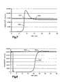
- Figs. 5-8 plot the conductivity (curves 300, 500 and 600) or concentration (curve 400) of column effluent over time.
- the conductivity/concentration of the solution fed into the column (302, 402, 502 and 602), as shown in each plot, is constant over the course of the experiment because the concentration of the solution fed into the column is constant.
- the conductivity/concentration of the column effluent rises above the conductivity/concentration of the example solution, see points 304, 404, 504 and 604. The exact cause of this rise is uncertain.
- Example 1 has an additional experimental parameter over the other experiments.
- the input solution was switched from the 36.4 mEg/L NaCl solution to distilled water.
- the perpendicular line 306 indicates the time at which the flow of distilled water was initiated and the flow of NaCl solution was stopped.
- the conductance of the effluent dropped to about zero shortly after the distilled water flow was initiated as would be expected because the conductivity of distilled water should be about zero.
- the short delay before the effluent conductance dropped is due to the short length of time it took for the distilled water to transit the column and emerge as effluent.
- Example 2 shows a conductance curve similar to example 2's concentration curve with the exception that only one NaCl solution was used.
- Example 4 as shown in Fig. 8 , exhibits a slightly different effluent conductance curve 600 than examples 1-3.
- the effluent conductance 600 does not rise as abruptly past the conductance value for the input solution 602. It is believed that this is most likely due to the presence of sodium bicarbonate in the input solution. With sodium bicarbonate a certain percentage of the sodium is believed to exchange for a proton before the bicarbonate can exchange for hydroxide thereby creating carbonic acid. The carbonic acid can then dissociate to water and carbon dioxide.
- the amount of sodium exchanged and the capacity per initial mass of resin for each example is shown in Table 2.
- the capacity of the column chosen is less than the theoretical capacity of the column. This level of exchange capacity is compatible with the commercially available SORB+ cartridge manufactured by Renal Solutions, Inc. (Warrendale, PA). It has been established by Renal Solutions that 80% of dialysis patients will produce a maximum of about 500 mEq of sodium ions during dialysis using the SORB+TM column. This number is only used here as an indicator of the effectiveness of the technique and columns could easily be provided that have capacities less than or greater than 500 mEq as required by a particular dialysis system.
Landscapes
- Health & Medical Sciences (AREA)
- Heart & Thoracic Surgery (AREA)
- Engineering & Computer Science (AREA)
- Urology & Nephrology (AREA)
- Life Sciences & Earth Sciences (AREA)
- Hematology (AREA)
- Veterinary Medicine (AREA)
- Public Health (AREA)
- Vascular Medicine (AREA)
- Anesthesiology (AREA)
- Biomedical Technology (AREA)
- General Health & Medical Sciences (AREA)
- Animal Behavior & Ethology (AREA)
- Emergency Medicine (AREA)
- Water Supply & Treatment (AREA)
- Chemical Kinetics & Catalysis (AREA)
- Chemical & Material Sciences (AREA)
- External Artificial Organs (AREA)
- Separation Using Semi-Permeable Membranes (AREA)
Claims (39)
- Eine Vorrichtung zur Zirkulation von Dialyseflüssigkeit umfassend:(a) ein Dialysator (20);(b) eine erste Behausung (30) die Material (34) enthält, das dazu geeignet ist, Natrium in Dialyseflüssigkeit, die durch die erste Behausung hindurch fließt, abzugeben;(c) eine zweite Behausung (32), die Material (36) enthält, das dazu geeignet ist, Natriumionen von Dialyseflüssigkeit, die durch die zweite Behausung hindurch fließt, zu binden;(d) hydraulische Leitungsteile (40-46) dazu ausgelegt, sich zwischen dem Dialysator, der ersten Behausung und der zweiten Behausung zu erstrecken, um den Dialysator mit der ersten und der zweiten Behausung in einem primären Fließweg für Dialyseflüssigkeit zu verbinden, um vom Dialysator zu der ersten Behausung, von der ersten Behausung zur zweiten Behausung und von der zweiten Behausung zurück zum Dialysator zu fließen;
charaktersisiert dadurch, dass:die hydraulischen Leitungsteile weiter dazu ausgelegt sind, einen Neben-Fließweg (46) für Dialyseflüssigkeit zu definieren, um die zweite Behausung durch Fließen von der ersten Behausung zurück zum Dialysator zu umgehen. - Die Vorrichtung nach Anspruch 1, weiter umfassend einen Fließregulator (116) für Flüssigkeit, der betriebsfähig ist, Flüsse von Dialyseflüssigkeit entlang des primären Fließwegs und des Neben-Fließwegs zu kontrollieren.
- Die Vorrichtung nach Anspruch 2, weiter umfassend einen Zähler (70), der betriebsfähig ist, die Konzentration an Natriumionen in der Dialyseflüssigkeit, welche aus der ersten Behausung hervorgeht, auszugeben.
- Die Vorrichtung nach Anspruch 3, weiter umfassend einen Kontroller (80), der betriebsfähig mit dem Regulator und dem Zähler verbunden ist, um den Regulator in Antwort auf die Konzentration an Natriumionen, die durch den Zähler ausgegeben wird, zu betätigen.
- Die Vorrichtung nach Anspruch 1, weiter umfassend eine Vorrichtung zur volumetrischen Ultrafiltration (110), die eine hydraulische Leitung, einen Fließregulator für Flüssigkeiten und ein Flüssigkeitsbehältnis in Flüssigkeits-Fließkommunikation mit dem Dialysator umfasst.
- Die Vorrichtung nach Anspruch 1, wobei der Dialysator, die erste Behausung, die zweite Behausung und die hydraulischen Leitungsteile verbundene Teile eines Systems zur Zirkulation von Dialyseflüssigkeit sind, das ein nichtexpandierbares Volumen hat.
- Die Vorrichtung nach Anspruch 6, wobei das nichtexpandierbare Volumen weniger ist als oder gleich groß ist wie ungefähr 3 Liter.
- Die Vorrichtung nach Anspruch 6, wobei das nichtexpandierbare Volumen weniger ist als oder gleich groß ist wie ungefähr 2 Liter.
- Die Vorrichtung nach Anspruch 6, wobei das nichtexpandierbare Volumen weniger ist als oder gleich groß ist wie ungefähr 1,5 Liter.
- Die Vorrichtung nach Anspruch 6, wobei das nichtexpandierbare Volumen ungefähr 1 Liter ist.
- Die Vorrichtung nach Anspruch 1, wobei das Material (36), das in der zweiten Behausung enthalten ist, ein Mischbett-Ionenaustauschharz umfasst.
- Die Vorrichtung nach Anspruch 11, wobei das Mischbett-Ionenaustauschharz eine Bindungskapazität für Natriumionen hat, die weniger ist als oder gleich groß ist wie ungefähr 800 mEq.
- Die Vorrichtung nach Anspruch 11, wobei das Mischbett-Ionenaustauschharz eine Bindungskapazität für Natriumionen hat, die weniger ist als oder gleich groß ist wie ungefähr 600 mEq.
- Die Vorrichtung nach Anspruch 11, wobei das Mischbett-Ionenaustauschharz eine Bindungskapazität für Natriumionen hat, die weniger ist als oder gleich groß ist wie ungefähr 500 mEq.
- Die Vorrichtung nach Anspruch 11, wobei das Mischbett-Ionenaustauschharz ein Kationenaustauschharz und ein Anionenaustauschharz umfasst.
- Die Vorrichtung nach Anspruch 15, wobei das Kationenonenaustauschharz ein sulfoniertes, sphärisches Styren-Divinyl-Benzol-Coploymer ist.
- Die Vorrichtung nach Anspruch 15, wobei das Anionenonenaustauschharz ein sphärisches, mit einem quartären Amin versehenes Styren-Divinyl-Benzol-Coploymer ist.
- Eine Vorrichtung zur Verwendung mit einem Dialyseflüssigkeits-System, das ein Material umfasst, das dazu geeignet ist, Natrium in Dialyseflüssigkeit, die in das System fließt, abzugeben, umfassend:(a) eine erste Behausung (30) die Material (34) enthält, das dazu geeignet ist, Natrium in Dialyseflüssigkeit, die durch die erste Behausung hindurch fließt, abzugeben;(b) eine zweite Behausung (32), die Material (36) enthält, das dazu geeignet ist, Natriumionen von Dialyseflüssigkeit, die durch die zweite Behausung hindurch fließt, zu binden;(c) hydraulische Leitungsteile (40-46) dazu ausgelegt, einen primären Fließweg zu definieren, wobei der primäre Fließweg einen Fließweg in die erste Behausung, einen Fließweg zwischen der ersten Behausung und der zweiten Behausung und einen Fließweg, der die zweiten Behausung verlässt, bereitstellt,
wobei die hydraulischen Leitungsteile dazu ausgelegt, einen Neben-Fließweg (46) zu definieren, wobei der Neben-Fließweg einen Fließweg bereitstellt, der den primären Fließweg zwischen der ersten Behausung und der zweiten Behausung mit dem primären Fließweg, der die zweite Behausung verlässt, verbindet; und(d) ein Fließregulator (116) für Flüssigkeit, der betriebsfähig ist, Flüsse von Dialiysierflüssigkeit entlang des primären Fließwegs und des Neben-Fließwegs zu kontrollieren. - Die Vorrichtung nach Anspruch 18, wobei das Material (36), das in der zweiten Behausung enthalten ist, ein Mischbett-Ionenaustauschharz ist.
- Die Vorrichtung nach Anspruch 19, wobei das Mischbett-Ionenaustauschharz ein Kationenaustauschharz und ein Anionenaustauschharz umfasst.
- Die Vorrichtung nach Anspruch 20, wobei das Kationenonenaustauschharz ein sulfoniertes, sphärisches Styren-Divinyl-Benzol-Coploymer ist.
- Die Vorrichtung nach Anspruch 20, wobei das Anionenonenaustauschharz ein sphärisches, mit einem quartären Amin versehenes Styren-Divinyl-Benzol-Coploymer ist.
- Die Vorrichtung nach Anspruch 19, wobei das Mischbett-Ionenaustauschharz eine Bindungskapazität für Natriumionen hat, die weniger ist als oder gleich groß ist wie ungefähr 800 mEq.
- Die Vorrichtung nach Anspruch 19, wobei das Mischbett-Ionenaustauschharz eine Bindungskapazität für Natriumionen hat, die weniger ist als oder gleich groß ist wie ungefähr 600 mEq.
- Die Vorrichtung nach Anspruch 19, wobei das Mischbett-Ionenaustauschharz eine Bindungskapazität für Natriumionen hat, die weniger ist als oder gleich groß ist wie ungefähr 500 mEq.
- Ein Verfahren , das folgende Schritte umfasst:a) Durchführen von Dialyseflüssigkeit durch einen Dialysator (20);b) Leiten der Dialyseflüssigkeit vom Dialysator zu der ersten Behausung (30), die Material (34) enthält, das Natriumionen in die Dialyseflüssigkeit abgibt;c) Durchführen der Dialyseflüssigkeit durch das Material in der ersten Behausung;d) Leiten der Dialyseflüssigkeit von der ersten Behausung zu einer zweiten Behausung (32), die Material (36) enthält, das Natriumionen von der Dialyseflüssigkeit bindet;e) Durchführen der Dialyseflüssigkeit durch das Material in der zweiten Behausung;f) Leiten der Dialyseflüssigkeit von der zweiten Behausung zurück zum Dialysator;
charakterisiert durchg) Messen der Natriumionenkonzentration in der Dialyseflüssigkeit, welche aus der ersten Behausung hervorgeht, und Führen eines Anteils der Dialyseflüssigkeit, um die zweite Behausung zu umgehen, wenn die gemessene Natriumionenkonzentration nicht größer ist als ein vorgegebenes Level. - Das Verfahren nach Anspruch 26, wobei das vorgegebene Level ungefähr 160 mEQ/L beträgt.
- Das Verfahren nach Anspruch 26, wobei das vorgegebene Level ungefähr 155 mEQ/L beträgt.
- Das Verfahren nach Anspruch 26, wobei das vorgegebene Level ungefähr 150 mEQ/L beträgt.
- Das Verfahren nach Anspruch 26, wobei das vorgegebene Level ungefähr 145 mEQ/L beträgt.
- Das Verfahren nach Anspruch 26, wobei die zweite Behausung ein Mischbett-Ionenaustauschharz enthält.
- Das Verfahren nach Anspruch 31, wobei das Mischbett-Ionenaustauschharz ein Kationenaustauschharz und ein Anionenaustauschharz umfasst.
- Das Verfahren nach Anspruch 32, wobei das Kationenonenaustauschharz ein sulfoniertes, sphärisches Styren-Divinyl-Benzol-Coploymer ist.
- Das Verfahren nach Anspruch 32, wobei das Anionenonenaustauschharz ein sphärisches, mit einem quartären Amin versehenes Styren-Divinyl-Benzol-Coploymer ist.
- Das Verfahren nach Anspruch 31, wobei das Mischbett-Ionenaustauschharz eine Bindungskapazität für Natriumionen hat, die weniger ist als oder gleich groß ist wie ungefähr 800 mEq.
- Das Verfahren nach Anspruch 31, wobei das Mischbett-Ionenaustauschharz eine Bindungskapazität für Natriumionen hat, die weniger ist als oder gleich groß ist wie ungefähr 600 mEq.
- Das Verfahren nach Anspruch 31, wobei das Mischbett-Ionenaustauschharz eine Bindungskapazität für Natriumionen hat, die weniger ist als oder gleich groß ist wie ungefähr 500 mEq.
- Das Verfahren nach Anspruch 31, weiter umfassend einen Schritt zum Bewirken von volumetrischer Ultrafiltration durch Umlenken von Dialyseflüssigkeit in ein Flüssigkeitsbehältnis.
- Das Verfahren nach Anspruch 31, wobei die Dialyseflüssigkeit Wasser umfasst, das zum Trinken geeignet ist.
Applications Claiming Priority (2)
| Application Number | Priority Date | Filing Date | Title |
|---|---|---|---|
| US57825704P | 2004-06-09 | 2004-06-09 | |
| PCT/US2005/020275 WO2005123230A2 (en) | 2004-06-09 | 2005-06-09 | Dialysis system |
Publications (3)
| Publication Number | Publication Date |
|---|---|
| EP1784248A2 EP1784248A2 (de) | 2007-05-16 |
| EP1784248A4 EP1784248A4 (de) | 2012-07-04 |
| EP1784248B1 true EP1784248B1 (de) | 2014-07-30 |
Family
ID=35510286
Family Applications (1)
| Application Number | Title | Priority Date | Filing Date |
|---|---|---|---|
| EP05759485.5A Expired - Lifetime EP1784248B1 (de) | 2004-06-09 | 2005-06-09 | Dialysesystem |
Country Status (4)
| Country | Link |
|---|---|
| US (2) | US7776210B2 (de) |
| EP (1) | EP1784248B1 (de) |
| JP (1) | JP4653170B2 (de) |
| WO (1) | WO2005123230A2 (de) |
Families Citing this family (147)
| Publication number | Priority date | Publication date | Assignee | Title |
|---|---|---|---|---|
| WO2006049822A1 (en) * | 2004-10-28 | 2006-05-11 | Nxstage Medical, Inc | Blood treatment dialyzer/filter design to trap entrained air in a fluid circuit |
| US20060217771A1 (en) | 2005-02-07 | 2006-09-28 | Medtronic, Inc. | Potassium monitoring |
| US20070102340A1 (en) * | 2005-10-27 | 2007-05-10 | Nxstage Medical, Inc. | Blood treatment filter and method of manufacturing |
| US7815809B2 (en) * | 2005-12-13 | 2010-10-19 | Gambro Lundia Ab | Method for conductivity calculation in a treatment fluid upstream and downstream a filtration unit in apparatuses for the blood treatment |
| US7981280B2 (en) * | 2006-01-06 | 2011-07-19 | Renal Solutions, Inc. | Recirculation of blood in an extracorporeal blood treatment system |
| US8876753B2 (en) | 2006-01-30 | 2014-11-04 | The Regents Of The University Of California | Peritoneal dialysis methods and apparatus |
| NZ593511A (en) | 2006-01-30 | 2012-09-28 | Univ California | Peritoneal dialysis methods and apparatus |
| US8366316B2 (en) * | 2006-04-14 | 2013-02-05 | Deka Products Limited Partnership | Sensor apparatus systems, devices and methods |
| EP2724736B1 (de) | 2006-04-14 | 2022-06-08 | DEKA Products Limited Partnership | Kassette mit eingehauster pumpe |
| US10537671B2 (en) | 2006-04-14 | 2020-01-21 | Deka Products Limited Partnership | Automated control mechanisms in a hemodialysis apparatus |
| US20080149563A1 (en) * | 2006-12-22 | 2008-06-26 | Renal Solutions, Inc. | Method of controlling dialysis using blood circulation times |
| US8631683B2 (en) | 2007-02-06 | 2014-01-21 | Fresenius Medical Care Holdings, Inc. | Dialysis systems including non-invasive multi-function sensor systems |
| US8042563B2 (en) | 2007-02-27 | 2011-10-25 | Deka Products Limited Partnership | Cassette system integrated apparatus |
| US8393690B2 (en) | 2007-02-27 | 2013-03-12 | Deka Products Limited Partnership | Enclosure for a portable hemodialysis system |
| US9517295B2 (en) | 2007-02-27 | 2016-12-13 | Deka Products Limited Partnership | Blood treatment systems and methods |
| US8425471B2 (en) | 2007-02-27 | 2013-04-23 | Deka Products Limited Partnership | Reagent supply for a hemodialysis system |
| US8491184B2 (en) | 2007-02-27 | 2013-07-23 | Deka Products Limited Partnership | Sensor apparatus systems, devices and methods |
| US8366655B2 (en) * | 2007-02-27 | 2013-02-05 | Deka Products Limited Partnership | Peritoneal dialysis sensor apparatus systems, devices and methods |
| US8409441B2 (en) | 2007-02-27 | 2013-04-02 | Deka Products Limited Partnership | Blood treatment systems and methods |
| US20090107335A1 (en) | 2007-02-27 | 2009-04-30 | Deka Products Limited Partnership | Air trap for a medical infusion device |
| US8357298B2 (en) | 2007-02-27 | 2013-01-22 | Deka Products Limited Partnership | Hemodialysis systems and methods |
| US9028691B2 (en) | 2007-02-27 | 2015-05-12 | Deka Products Limited Partnership | Blood circuit assembly for a hemodialysis system |
| US8562834B2 (en) | 2007-02-27 | 2013-10-22 | Deka Products Limited Partnership | Modular assembly for a portable hemodialysis system |
| CN101711171B (zh) | 2007-02-27 | 2014-03-26 | 德卡产品有限公司 | 血液透析系统及方法 |
| US9199022B2 (en) | 2008-09-12 | 2015-12-01 | Fresenius Medical Care Holdings, Inc. | Modular reservoir assembly for a hemodialysis and hemofiltration system |
| US9358331B2 (en) | 2007-09-13 | 2016-06-07 | Fresenius Medical Care Holdings, Inc. | Portable dialysis machine with improved reservoir heating system |
| US8597505B2 (en) | 2007-09-13 | 2013-12-03 | Fresenius Medical Care Holdings, Inc. | Portable dialysis machine |
| US9308307B2 (en) | 2007-09-13 | 2016-04-12 | Fresenius Medical Care Holdings, Inc. | Manifold diaphragms |
| US8240636B2 (en) | 2009-01-12 | 2012-08-14 | Fresenius Medical Care Holdings, Inc. | Valve system |
| US8105487B2 (en) | 2007-09-25 | 2012-01-31 | Fresenius Medical Care Holdings, Inc. | Manifolds for use in conducting dialysis |
| US10035103B2 (en) | 2008-10-30 | 2018-07-31 | Fresenius Medical Care Holdings, Inc. | Modular, portable dialysis system |
| US8771508B2 (en) | 2008-08-27 | 2014-07-08 | Deka Products Limited Partnership | Dialyzer cartridge mounting arrangement for a hemodialysis system |
| US8889004B2 (en) | 2007-11-16 | 2014-11-18 | Fresenius Medical Care Holdings, Inc. | Dialysis systems and methods |
| CA2704011C (en) * | 2007-11-16 | 2016-07-05 | Fresenius Medical Care Holdings, Inc. | Dialysis systems and methods |
| EP3511034B1 (de) | 2007-11-29 | 2023-03-29 | Fresenius Medical Care Holdings, Inc. | System zur extrakorporalen blutbehandlung und durchführung von hämodialyse und hämofiltration |
| US8640887B2 (en) * | 2008-10-03 | 2014-02-04 | Fresenius Medical Care Holdings, Inc. | Zirconium phosphate particles having improved adsorption capacity and method of synthesizing the same |
| AU2009302327C1 (en) | 2008-10-07 | 2015-09-10 | Fresenius Medical Care Holdings, Inc. | Priming system and method for dialysis systems |
| USD611152S1 (en) | 2009-05-18 | 2010-03-02 | Fresenius Medical Care Holdings, Inc. | Dialysis system sorbent cartridge mount |
| US8080161B2 (en) * | 2009-06-11 | 2011-12-20 | Baxter International Inc. | Dialysis treatment devices for removing urea |
| US9526820B2 (en) | 2009-08-04 | 2016-12-27 | Fresenius Medical Care Holdings, Inc. | Dialysis systems, components, and methods |
| US9399091B2 (en) | 2009-09-30 | 2016-07-26 | Medtronic, Inc. | System and method to regulate ultrafiltration |
| JP2013509271A (ja) | 2009-10-30 | 2013-03-14 | デカ・プロダクツ・リミテッド・パートナーシップ | 血管アクセスデバイスの離脱を検知するための装置および方法 |
| JP5560347B2 (ja) | 2009-12-07 | 2014-07-23 | フレセニウス メディカル ケア ホールディングス インコーポレーテッド | ジルコニウムイオン交換収着剤を用いた浄水カートリッジ |
| US8529491B2 (en) * | 2009-12-31 | 2013-09-10 | Fresenius Medical Care Holdings, Inc. | Detecting blood flow degradation |
| US8449686B2 (en) | 2010-04-26 | 2013-05-28 | Fresenius Medical Care Holdings, Inc. | Methods for cleaning a drain line of a dialysis machine |
| US8784668B2 (en) | 2010-10-12 | 2014-07-22 | Fresenius Medical Care Holdings, Inc. | Systems and methods for compensation of compliant behavior in regenerative dialysis systems |
| US8641659B2 (en) | 2011-02-17 | 2014-02-04 | Medtronic, Inc. | Method and device to treat kidney disease |
| US8945936B2 (en) | 2011-04-06 | 2015-02-03 | Fresenius Medical Care Holdings, Inc. | Measuring chemical properties of a sample fluid in dialysis systems |
| US9456755B2 (en) | 2011-04-29 | 2016-10-04 | Medtronic, Inc. | Method and device to monitor patients with kidney disease |
| US9848778B2 (en) | 2011-04-29 | 2017-12-26 | Medtronic, Inc. | Method and device to monitor patients with kidney disease |
| US9750862B2 (en) | 2011-04-29 | 2017-09-05 | Medtronic, Inc. | Adaptive system for blood fluid removal |
| US9017277B2 (en) | 2011-05-02 | 2015-04-28 | Medtronic, Inc. | System and implantable device for treating chronic kidney disease |
| US9333286B2 (en) | 2011-05-12 | 2016-05-10 | Fresenius Medical Care Holdings, Inc. | Medical tubing installation detection |
| US8836519B2 (en) | 2011-05-12 | 2014-09-16 | Fresenius Medical Care Holdings, Inc. | Determining the absence or presence of fluid in a dialysis system |
| CA3166031A1 (en) | 2011-05-24 | 2012-11-29 | Deka Products Limited Partnership | Hemodialysis system |
| US20130030356A1 (en) * | 2011-07-29 | 2013-01-31 | Baxter Healthcare S.A. | Sodium management for dialysis systems |
| ES2562466T3 (es) * | 2011-07-29 | 2016-03-04 | Baxter International Inc. | Gestión de sodio para sistemas de diálisis |
| CN103889481B (zh) | 2011-08-02 | 2016-03-09 | 美敦力公司 | 带有具有可控的顺应性容积的流动路径的血液透析系统 |
| US10857277B2 (en) | 2011-08-16 | 2020-12-08 | Medtronic, Inc. | Modular hemodialysis system |
| WO2013028809A2 (en) | 2011-08-22 | 2013-02-28 | Medtronic, Inc. | Dual flow sorbent cartridge |
| US8906240B2 (en) | 2011-08-29 | 2014-12-09 | Fresenius Medical Care Holdings, Inc. | Early detection of low bicarbonate level |
| US8992777B2 (en) | 2011-11-18 | 2015-03-31 | Fresenius Medical Care Holdings, Inc. | Systems and methods for providing notifications in dialysis systems |
| WO2013103906A1 (en) | 2012-01-04 | 2013-07-11 | Medtronic, Inc. | Multi-staged filtration system for blood fluid removal |
| US9165112B2 (en) | 2012-02-03 | 2015-10-20 | Fresenius Medical Care Holdings, Inc. | Systems and methods for displaying objects at a medical treatment apparatus display screen |
| PL2644215T3 (pl) * | 2012-03-28 | 2015-04-30 | Gambro Lundia Ab | Aparat do pozaustrojowej obróbki krwi |
| ES2609592T3 (es) | 2012-09-28 | 2017-04-21 | Gambro Lundia Ab | Aparato de tratamiento sanguíneo extracorpóreo y método de configuración de un tratamiento sanguíneo extracorpóreo |
| US10905816B2 (en) * | 2012-12-10 | 2021-02-02 | Medtronic, Inc. | Sodium management system for hemodialysis |
| US9201036B2 (en) | 2012-12-21 | 2015-12-01 | Fresenius Medical Care Holdings, Inc. | Method and system of monitoring electrolyte levels and composition using capacitance or induction |
| US9157786B2 (en) | 2012-12-24 | 2015-10-13 | Fresenius Medical Care Holdings, Inc. | Load suspension and weighing system for a dialysis machine reservoir |
| US11565029B2 (en) | 2013-01-09 | 2023-01-31 | Medtronic, Inc. | Sorbent cartridge with electrodes |
| US9713666B2 (en) | 2013-01-09 | 2017-07-25 | Medtronic, Inc. | Recirculating dialysate fluid circuit for blood measurement |
| US9707328B2 (en) | 2013-01-09 | 2017-07-18 | Medtronic, Inc. | Sorbent cartridge to measure solute concentrations |
| US11154648B2 (en) | 2013-01-09 | 2021-10-26 | Medtronic, Inc. | Fluid circuits for sorbent cartridge with sensors |
| US10478543B2 (en) | 2013-01-11 | 2019-11-19 | The Charles Stark Draper Laboratory, Inc. | Systems and methods for increasing convective clearance of undesired particles in a microfluidic device |
| US10603419B2 (en) | 2013-01-11 | 2020-03-31 | The Charles Stark Draper Laboratories, Inc. | Systems and methods for increasing convective clearance of undesired particles in a microfluidic device |
| US10342909B2 (en) * | 2013-01-11 | 2019-07-09 | The Charles Stark Draper Laboratory Inc. | Systems and methods for increasing convective clearance of undesired particles in a microfluidic device |
| US10850016B2 (en) | 2013-02-01 | 2020-12-01 | Medtronic, Inc. | Modular fluid therapy system having jumpered flow paths and systems and methods for cleaning and disinfection |
| US9623164B2 (en) | 2013-02-01 | 2017-04-18 | Medtronic, Inc. | Systems and methods for multifunctional volumetric fluid control |
| US10010663B2 (en) | 2013-02-01 | 2018-07-03 | Medtronic, Inc. | Fluid circuit for delivery of renal replacement therapies |
| US9526822B2 (en) | 2013-02-01 | 2016-12-27 | Medtronic, Inc. | Sodium and buffer source cartridges for use in a modular controlled compliant flow path |
| US10543052B2 (en) | 2013-02-01 | 2020-01-28 | Medtronic, Inc. | Portable dialysis cabinet |
| WO2014121160A1 (en) * | 2013-02-01 | 2014-08-07 | Medtronic, Inc. | Sorbent cartridge with electrodes |
| US9827361B2 (en) | 2013-02-02 | 2017-11-28 | Medtronic, Inc. | pH buffer measurement system for hemodialysis systems |
| US9144640B2 (en) | 2013-02-02 | 2015-09-29 | Medtronic, Inc. | Sorbent cartridge configurations for improved dialysate regeneration |
| US9433721B2 (en) | 2013-06-25 | 2016-09-06 | Fresenius Medical Care Holdings, Inc. | Vial spiking assemblies and related methods |
| US10076283B2 (en) | 2013-11-04 | 2018-09-18 | Medtronic, Inc. | Method and device to manage fluid volumes in the body |
| US9354640B2 (en) | 2013-11-11 | 2016-05-31 | Fresenius Medical Care Holdings, Inc. | Smart actuator for valve |
| US9943780B2 (en) | 2013-11-26 | 2018-04-17 | Medtronic, Inc. | Module for in-line recharging of sorbent materials with optional bypass |
| US10052624B2 (en) | 2013-11-26 | 2018-08-21 | Medtronic, Inc. | Zirconium phosphate and zirconium oxide recharging flow paths |
| US10064986B2 (en) | 2013-11-26 | 2018-09-04 | Medtronic, Inc. | Recharger for recharging zirconium phosphate and zirconium oxide modules |
| US10537875B2 (en) | 2013-11-26 | 2020-01-21 | Medtronic, Inc. | Precision recharging of sorbent materials using patient and session data |
| US10099215B2 (en) | 2013-11-26 | 2018-10-16 | Medtronic, Inc. | Management of recharger effluent pH |
| US9884145B2 (en) | 2013-11-26 | 2018-02-06 | Medtronic, Inc. | Parallel modules for in-line recharging of sorbents using alternate duty cycles |
| US9974896B2 (en) | 2014-06-24 | 2018-05-22 | Medtronic, Inc. | Method of zirconium phosphate recharging |
| US10099214B2 (en) | 2013-11-26 | 2018-10-16 | Medtronic, Inc. | Zirconium phosphate and zirconium oxide recharger control logic and operational process algorithms |
| US10052612B2 (en) | 2013-11-26 | 2018-08-21 | Medtronic, Inc. | Zirconium phosphate recharging method and apparatus |
| US10004839B2 (en) | 2013-11-26 | 2018-06-26 | Medtronic, Inc. | Multi-use sorbent cartridge |
| US9895477B2 (en) | 2013-11-26 | 2018-02-20 | Medtronic, Inc. | Detachable module for recharging sorbent materials with optional bypass |
| US10595775B2 (en) | 2013-11-27 | 2020-03-24 | Medtronic, Inc. | Precision dialysis monitoring and synchronization system |
| WO2015126879A1 (en) * | 2014-02-19 | 2015-08-27 | Medtronic, Inc. | Module for in-line recharging of sorbent materials with optional bypass |
| AU2015219213B2 (en) * | 2014-02-19 | 2019-04-04 | Medtronic, Inc. | Parallel modules for in-line recharging of sorbents using alternate duty cycles |
| EP3160533B1 (de) | 2014-06-24 | 2020-08-12 | Medtronic Inc. | Sorptionsmittelbeutel |
| EP3160531B1 (de) | 2014-06-24 | 2019-08-14 | Medtronic Inc. | Auffüllung von urease in dialysesystemen unter verwendung eines ureaseeinführers |
| CN106604752B (zh) | 2014-06-24 | 2019-07-09 | 美敦力公司 | 用于补充吸附剂盒内的脲酶的脲酶引入系统 |
| EP3160535B1 (de) | 2014-06-24 | 2024-10-02 | Mozarc Medical US LLC | Modulare dialysatregenerationsanordnung |
| US10004838B2 (en) | 2014-06-24 | 2018-06-26 | Medtronic, Inc. | Reserve zirconium phosphate module for use in sorbent dialysis |
| CN106659827B (zh) | 2014-06-24 | 2019-07-09 | 美敦力公司 | 使用脲酶袋补充透析系统中的脲酶 |
| US10357757B2 (en) | 2014-06-24 | 2019-07-23 | Medtronic, Inc. | Stacked sorbent assembly |
| US9895479B2 (en) | 2014-12-10 | 2018-02-20 | Medtronic, Inc. | Water management system for use in dialysis |
| US10098993B2 (en) | 2014-12-10 | 2018-10-16 | Medtronic, Inc. | Sensing and storage system for fluid balance |
| US10874787B2 (en) | 2014-12-10 | 2020-12-29 | Medtronic, Inc. | Degassing system for dialysis |
| US9713665B2 (en) | 2014-12-10 | 2017-07-25 | Medtronic, Inc. | Degassing system for dialysis |
| US9974942B2 (en) | 2015-06-19 | 2018-05-22 | Fresenius Medical Care Holdings, Inc. | Non-vented vial drug delivery |
| US10335534B2 (en) | 2015-11-06 | 2019-07-02 | Medtronic, Inc. | Dialysis prescription optimization for decreased arrhythmias |
| US10874790B2 (en) | 2016-08-10 | 2020-12-29 | Medtronic, Inc. | Peritoneal dialysis intracycle osmotic agent adjustment |
| US10994064B2 (en) | 2016-08-10 | 2021-05-04 | Medtronic, Inc. | Peritoneal dialysate flow path sensing |
| US12329892B2 (en) | 2016-04-04 | 2025-06-17 | Mozarc Medical Us Llc | Dextrose concentration sensor for a peritoneal dialysis system |
| EP3272375A1 (de) | 2016-07-22 | 2018-01-24 | Fraunhofer-Gesellschaft zur Förderung der angewandten Forschung e.V. | Vorrichtung und verfahren zur erzeugung eines dialysats zur dialyse |
| US11013843B2 (en) | 2016-09-09 | 2021-05-25 | Medtronic, Inc. | Peritoneal dialysis fluid testing system |
| US10981148B2 (en) | 2016-11-29 | 2021-04-20 | Medtronic, Inc. | Zirconium oxide module conditioning |
| JP2019536570A (ja) | 2016-12-05 | 2019-12-19 | テマセク ポリテクニックTemasek Polytechnic | 透析デバイスおよび透析システムのための吸着剤 |
| US11167070B2 (en) | 2017-01-30 | 2021-11-09 | Medtronic, Inc. | Ganged modular recharging system |
| US10960381B2 (en) | 2017-06-15 | 2021-03-30 | Medtronic, Inc. | Zirconium phosphate disinfection recharging and conditioning |
| DE102017116097A1 (de) * | 2017-07-18 | 2019-01-24 | B. Braun Avitum Ag | Vorrichtung und Verfahren zur Durchführung einer isonaträmischen Dialyse |
| US11278654B2 (en) | 2017-12-07 | 2022-03-22 | Medtronic, Inc. | Pneumatic manifold for a dialysis system |
| US11033667B2 (en) | 2018-02-02 | 2021-06-15 | Medtronic, Inc. | Sorbent manifold for a dialysis system |
| US11110215B2 (en) | 2018-02-23 | 2021-09-07 | Medtronic, Inc. | Degasser and vent manifolds for dialysis |
| WO2020028096A1 (en) | 2018-07-30 | 2020-02-06 | Fresenius Medical Care Holdings, Inc. | Valve actuation systems and related methods |
| EP4233984B1 (de) | 2018-07-31 | 2025-11-05 | Fresenius Medical Care Holdings, Inc. | Drehventile für dialysesysteme |
| US12285552B2 (en) | 2018-08-14 | 2025-04-29 | Mozarc Medical Us Llc | Precision dialysis therapy based on sorbent effluent analysis |
| US11213616B2 (en) | 2018-08-24 | 2022-01-04 | Medtronic, Inc. | Recharge solution for zirconium phosphate |
| US11806457B2 (en) | 2018-11-16 | 2023-11-07 | Mozarc Medical Us Llc | Peritoneal dialysis adequacy meaurements |
| CN113423456B (zh) | 2018-12-07 | 2024-03-19 | 费森尤斯医疗保健控股公司 | 用于管理医疗系统中的流体流动的旋转阀 |
| US11806456B2 (en) | 2018-12-10 | 2023-11-07 | Mozarc Medical Us Llc | Precision peritoneal dialysis therapy based on dialysis adequacy measurements |
| US12433976B2 (en) | 2019-01-08 | 2025-10-07 | Mozarc Medical Us Llc | Bicarbonate sensor for dialysis |
| US11607669B2 (en) | 2019-02-20 | 2023-03-21 | Medtronic, Inc. | Precision recharging based on sorbent module manufacturing characteristics |
| EP3976133B1 (de) | 2019-08-05 | 2024-01-24 | Fresenius Medical Care Holdings, Inc. | Leitfähigkeitskontrollsysteme |
| WO2021119401A1 (en) | 2019-12-12 | 2021-06-17 | Fresenius Medical Care Holdings, Inc. | Blood treatment systems |
| US12290621B2 (en) | 2020-04-13 | 2025-05-06 | Temasek Polytechnic | Dialysate regenerator comprising reversible retainer |
| US12128165B2 (en) | 2020-04-27 | 2024-10-29 | Mozarc Medical Us Llc | Dual stage degasser |
| US12569601B2 (en) | 2021-04-07 | 2026-03-10 | Mozarc Medical Us Llc | Increased operational capabilities of a dialysis system |
| US12397093B2 (en) | 2021-05-18 | 2025-08-26 | Mozarc Medical Us Llc | Sorbent cartridge designs |
| US12154673B2 (en) | 2021-08-02 | 2024-11-26 | Mozarc Medical Us Llc | Artificial intelligence assisted home therapy settings for dialysis |
| US11850344B2 (en) | 2021-08-11 | 2023-12-26 | Mozarc Medical Us Llc | Gas bubble sensor |
| US11965763B2 (en) | 2021-11-12 | 2024-04-23 | Mozarc Medical Us Llc | Determining fluid flow across rotary pump |
| US11944733B2 (en) | 2021-11-18 | 2024-04-02 | Mozarc Medical Us Llc | Sodium and bicarbonate control |
| WO2024043193A1 (ja) * | 2022-08-23 | 2024-02-29 | フィジオロガス・テクノロジーズ株式会社 | 対象液処理装置 |
Family Cites Families (32)
| Publication number | Priority date | Publication date | Assignee | Title |
|---|---|---|---|---|
| US3441136A (en) * | 1966-07-07 | 1969-04-29 | Milton Roy Co | Controlled blood dialysis system |
| GB1189458A (en) * | 1967-09-27 | 1970-04-29 | Nat Res Dev | Improvements in or relating to dialysers |
| US3506126A (en) * | 1968-05-03 | 1970-04-14 | Milton Roy Co | Closed recirculating hemodialysis system |
| GB1267105A (de) * | 1968-12-02 | 1972-03-15 | ||
| US3669880A (en) * | 1969-06-30 | 1972-06-13 | Cci Aerospace Corp | Recirculation dialysate system for use with an artificial kidney machine |
| BE759038A (fr) * | 1969-11-17 | 1971-04-30 | Cci Aerospace Corp | Module a dialysat a remise en circulation, destine a etre jete |
| US3697418A (en) * | 1971-01-25 | 1972-10-10 | Cci Aerospace Corp | Method and apparatus for regenerating the dialyzing fluid for an artificial kidney |
| JPS5226076B2 (de) * | 1972-10-06 | 1977-07-12 | ||
| US4036747A (en) * | 1973-02-27 | 1977-07-19 | Takeda Chemical Industries, Ltd. | Adsorbent for recycling artificial kidney |
| US4118314A (en) * | 1974-01-09 | 1978-10-03 | Seisan Kaihatsu Kagaku Kenkyusho | Apparatus for treatment of artificial kidney dialyzing fluid |
| SE7403799L (de) * | 1974-03-21 | 1975-09-22 | Gambro Ab | |
| IT1014620B (it) * | 1974-05-06 | 1977-04-30 | Bellco Spa | Procedimento per la rigenerazione di liquidi dializzanti in sistemi di emodialisi |
| US4366051A (en) * | 1976-11-19 | 1982-12-28 | Halbert Fischel | Hemodialysis system |
| NL7703937A (nl) * | 1977-04-12 | 1978-10-16 | Organon Teknika Bv | Inrichting voorzien van een sorbent voor het zuiveren van bloed; een voor orale toepassing geschikt sorbent en een werkwijze voor vervaar- diging van het sorbent. |
| US4581141A (en) * | 1978-02-27 | 1986-04-08 | Purdue Research Foundation | Dialysis material and method for removing uremic substances |
| US4209392A (en) * | 1978-05-15 | 1980-06-24 | Wallace Richard A | Portable hepatic-assist method and apparatus for same |
| US4247393A (en) * | 1979-01-11 | 1981-01-27 | Wallace Richard A | Hemodialysis assist device |
| US4564455A (en) * | 1983-12-13 | 1986-01-14 | The Graver Company | Three component resin system and method for purifying aqueous solutions |
| JPH089030B2 (ja) * | 1987-12-21 | 1996-01-31 | 三菱電機株式会社 | イオン交換樹脂による水のpH制御方法 |
| US5277820A (en) * | 1992-02-06 | 1994-01-11 | Hemocleanse, Inc. | Device and method for extracorporeal blood treatment |
| US5536412A (en) * | 1992-02-06 | 1996-07-16 | Hemocleanse, Inc. | Hemofiltration and plasmafiltration devices and methods |
| US6156007A (en) * | 1992-09-04 | 2000-12-05 | Hemotherm, Inc. | Apparatus for whole-body hyperthermia |
| US5685988A (en) * | 1993-09-15 | 1997-11-11 | Malchesky; Paul | Dialysis process and system |
| US6332985B1 (en) * | 1999-03-29 | 2001-12-25 | Uop Llc | Process for removing toxins from bodily fluids using zirconium or titanium microporous compositions |
| US6099737A (en) * | 1999-03-29 | 2000-08-08 | Uop Llc | Process for removing toxins from blood using zirconium metallate or titanium metallate compositions |
| US7033498B2 (en) * | 2000-11-28 | 2006-04-25 | Renal Solutions, Inc. | Cartridges useful in cleaning dialysis solutions |
| US6579460B1 (en) * | 2001-03-13 | 2003-06-17 | Uop Llc | Process and composition for removing toxins from bodily fluids |
| US6582955B2 (en) * | 2001-05-11 | 2003-06-24 | Spectrum Laboratories, Inc. | Bioreactor with application as blood therapy device |
| US7241272B2 (en) * | 2001-11-13 | 2007-07-10 | Baxter International Inc. | Method and composition for removing uremic toxins in dialysis processes |
| US6960179B2 (en) * | 2001-11-16 | 2005-11-01 | National Quality Care, Inc | Wearable continuous renal replacement therapy device |
| EP1523350B1 (de) * | 2002-07-19 | 2011-04-13 | Baxter International Inc. | System für die peritonealdialyse |
| US20040099593A1 (en) * | 2002-11-25 | 2004-05-27 | Potito De Paolis | Concurrent dialysate purification cartridge |
-
2005
- 2005-06-09 JP JP2007527721A patent/JP4653170B2/ja not_active Expired - Fee Related
- 2005-06-09 US US11/148,928 patent/US7776210B2/en not_active Expired - Fee Related
- 2005-06-09 EP EP05759485.5A patent/EP1784248B1/de not_active Expired - Lifetime
- 2005-06-09 WO PCT/US2005/020275 patent/WO2005123230A2/en not_active Ceased
-
2010
- 2010-06-30 US US12/827,617 patent/US7947179B2/en not_active Expired - Fee Related
Also Published As
| Publication number | Publication date |
|---|---|
| EP1784248A2 (de) | 2007-05-16 |
| HK1113555A1 (en) | 2008-10-10 |
| WO2005123230A2 (en) | 2005-12-29 |
| US7776210B2 (en) | 2010-08-17 |
| JP4653170B2 (ja) | 2011-03-16 |
| WO2005123230A3 (en) | 2006-10-12 |
| US20100326911A1 (en) | 2010-12-30 |
| US20050274658A1 (en) | 2005-12-15 |
| US7947179B2 (en) | 2011-05-24 |
| EP1784248A4 (de) | 2012-07-04 |
| JP2008502449A (ja) | 2008-01-31 |
Similar Documents
| Publication | Publication Date | Title |
|---|---|---|
| EP1784248B1 (de) | Dialysesystem | |
| US10821214B2 (en) | Urease introduction system for replenishing urease in a sorbent cartridge | |
| EP1345687B1 (de) | Bei der reinigungvondialyselösungen nützliche patronen | |
| CN104994894B (zh) | 血液透析用的钠管理系统 | |
| CN104168934B (zh) | 用于移除透析过程中的尿毒症毒素的方法和组合物 | |
| CN103747818B (zh) | 透析系统的钠管理 | |
| US9023185B2 (en) | Low scale potential water treatment | |
| US20020112609A1 (en) | Cartridges useful in cleaning dialysis solutions | |
| CN105120913A (zh) | 用于模块化受控相容流路的钠和缓冲液源盒 | |
| JP2004525747A5 (de) | ||
| CA2656468C (en) | Electrodeionization apparatus and low scale potential water treatment | |
| AU2014242274A1 (en) | Hemodialysis and peritoneal dialysis systems having electrodialysis and electrodeionization capabilities | |
| CN115835893B (zh) | 透析液再生器及包含其的系统 | |
| HK1113555B (en) | Dialysis system | |
| CN118159312B (zh) | 透析液再生循环系统及透析设备 | |
| CN119215253A (zh) | 透析液再生系统及透析设备 | |
| HK1230117A1 (en) | Method for treating dialysate, dialysis system, and method for pre-evaluating dialysis patients for treatment with same | |
| HK1059061B (en) | Cartridges useful in cleaning dialysis solutions |
Legal Events
| Date | Code | Title | Description |
|---|---|---|---|
| PUAI | Public reference made under article 153(3) epc to a published international application that has entered the european phase |
Free format text: ORIGINAL CODE: 0009012 |
|
| 17P | Request for examination filed |
Effective date: 20070105 |
|
| AK | Designated contracting states |
Kind code of ref document: A2 Designated state(s): AT BE BG CH CY CZ DE DK EE ES FI FR GB GR HU IE IS IT LI LT LU MC NL PL PT RO SE SI SK TR |
|
| AX | Request for extension of the european patent |
Extension state: AL BA HR LV MK YU |
|
| REG | Reference to a national code |
Ref country code: HK Ref legal event code: DE Ref document number: 1113555 Country of ref document: HK |
|
| A4 | Supplementary search report drawn up and despatched |
Effective date: 20120606 |
|
| RIC1 | Information provided on ipc code assigned before grant |
Ipc: B01D 61/26 20060101AFI20120531BHEP Ipc: A61M 1/16 20060101ALI20120531BHEP |
|
| 17Q | First examination report despatched |
Effective date: 20130314 |
|
| GRAP | Despatch of communication of intention to grant a patent |
Free format text: ORIGINAL CODE: EPIDOSNIGR1 |
|
| INTG | Intention to grant announced |
Effective date: 20140127 |
|
| GRAS | Grant fee paid |
Free format text: ORIGINAL CODE: EPIDOSNIGR3 |
|
| GRAA | (expected) grant |
Free format text: ORIGINAL CODE: 0009210 |
|
| AK | Designated contracting states |
Kind code of ref document: B1 Designated state(s): AT BE BG CH CY CZ DE DK EE ES FI FR GB GR HU IE IS IT LI LT LU MC NL PL PT RO SE SI SK TR |
|
| AX | Request for extension of the european patent |
Extension state: AL BA HR LV MK YU |
|
| REG | Reference to a national code |
Ref country code: GB Ref legal event code: FG4D |
|
| REG | Reference to a national code |
Ref country code: CH Ref legal event code: EP |
|
| REG | Reference to a national code |
Ref country code: AT Ref legal event code: REF Ref document number: 679672 Country of ref document: AT Kind code of ref document: T Effective date: 20140815 |
|
| REG | Reference to a national code |
Ref country code: IE Ref legal event code: FG4D |
|
| REG | Reference to a national code |
Ref country code: DE Ref legal event code: R096 Ref document number: 602005044358 Country of ref document: DE Effective date: 20140911 |
|
| REG | Reference to a national code |
Ref country code: SE Ref legal event code: TRGR |
|
| REG | Reference to a national code |
Ref country code: HK Ref legal event code: GR Ref document number: 1113555 Country of ref document: HK |
|
| REG | Reference to a national code |
Ref country code: AT Ref legal event code: MK05 Ref document number: 679672 Country of ref document: AT Kind code of ref document: T Effective date: 20140730 |
|
| REG | Reference to a national code |
Ref country code: NL Ref legal event code: VDEP Effective date: 20140730 |
|
| REG | Reference to a national code |
Ref country code: LT Ref legal event code: MG4D |
|
| PG25 | Lapsed in a contracting state [announced via postgrant information from national office to epo] |
Ref country code: FI Free format text: LAPSE BECAUSE OF FAILURE TO SUBMIT A TRANSLATION OF THE DESCRIPTION OR TO PAY THE FEE WITHIN THE PRESCRIBED TIME-LIMIT Effective date: 20140730 Ref country code: GR Free format text: LAPSE BECAUSE OF FAILURE TO SUBMIT A TRANSLATION OF THE DESCRIPTION OR TO PAY THE FEE WITHIN THE PRESCRIBED TIME-LIMIT Effective date: 20141031 Ref country code: ES Free format text: LAPSE BECAUSE OF FAILURE TO SUBMIT A TRANSLATION OF THE DESCRIPTION OR TO PAY THE FEE WITHIN THE PRESCRIBED TIME-LIMIT Effective date: 20140730 Ref country code: BG Free format text: LAPSE BECAUSE OF FAILURE TO SUBMIT A TRANSLATION OF THE DESCRIPTION OR TO PAY THE FEE WITHIN THE PRESCRIBED TIME-LIMIT Effective date: 20141030 Ref country code: LT Free format text: LAPSE BECAUSE OF FAILURE TO SUBMIT A TRANSLATION OF THE DESCRIPTION OR TO PAY THE FEE WITHIN THE PRESCRIBED TIME-LIMIT Effective date: 20140730 Ref country code: PT Free format text: LAPSE BECAUSE OF FAILURE TO SUBMIT A TRANSLATION OF THE DESCRIPTION OR TO PAY THE FEE WITHIN THE PRESCRIBED TIME-LIMIT Effective date: 20141202 |
|
| PG25 | Lapsed in a contracting state [announced via postgrant information from national office to epo] |
Ref country code: IS Free format text: LAPSE BECAUSE OF FAILURE TO SUBMIT A TRANSLATION OF THE DESCRIPTION OR TO PAY THE FEE WITHIN THE PRESCRIBED TIME-LIMIT Effective date: 20141130 Ref country code: PL Free format text: LAPSE BECAUSE OF FAILURE TO SUBMIT A TRANSLATION OF THE DESCRIPTION OR TO PAY THE FEE WITHIN THE PRESCRIBED TIME-LIMIT Effective date: 20140730 Ref country code: NL Free format text: LAPSE BECAUSE OF FAILURE TO SUBMIT A TRANSLATION OF THE DESCRIPTION OR TO PAY THE FEE WITHIN THE PRESCRIBED TIME-LIMIT Effective date: 20140730 Ref country code: CY Free format text: LAPSE BECAUSE OF FAILURE TO SUBMIT A TRANSLATION OF THE DESCRIPTION OR TO PAY THE FEE WITHIN THE PRESCRIBED TIME-LIMIT Effective date: 20140730 Ref country code: AT Free format text: LAPSE BECAUSE OF FAILURE TO SUBMIT A TRANSLATION OF THE DESCRIPTION OR TO PAY THE FEE WITHIN THE PRESCRIBED TIME-LIMIT Effective date: 20140730 |
|
| PG25 | Lapsed in a contracting state [announced via postgrant information from national office to epo] |
Ref country code: RO Free format text: LAPSE BECAUSE OF FAILURE TO SUBMIT A TRANSLATION OF THE DESCRIPTION OR TO PAY THE FEE WITHIN THE PRESCRIBED TIME-LIMIT Effective date: 20140730 Ref country code: CZ Free format text: LAPSE BECAUSE OF FAILURE TO SUBMIT A TRANSLATION OF THE DESCRIPTION OR TO PAY THE FEE WITHIN THE PRESCRIBED TIME-LIMIT Effective date: 20140730 Ref country code: SK Free format text: LAPSE BECAUSE OF FAILURE TO SUBMIT A TRANSLATION OF THE DESCRIPTION OR TO PAY THE FEE WITHIN THE PRESCRIBED TIME-LIMIT Effective date: 20140730 Ref country code: DK Free format text: LAPSE BECAUSE OF FAILURE TO SUBMIT A TRANSLATION OF THE DESCRIPTION OR TO PAY THE FEE WITHIN THE PRESCRIBED TIME-LIMIT Effective date: 20140730 Ref country code: EE Free format text: LAPSE BECAUSE OF FAILURE TO SUBMIT A TRANSLATION OF THE DESCRIPTION OR TO PAY THE FEE WITHIN THE PRESCRIBED TIME-LIMIT Effective date: 20140730 |
|
| REG | Reference to a national code |
Ref country code: DE Ref legal event code: R097 Ref document number: 602005044358 Country of ref document: DE |
|
| PLBE | No opposition filed within time limit |
Free format text: ORIGINAL CODE: 0009261 |
|
| STAA | Information on the status of an ep patent application or granted ep patent |
Free format text: STATUS: NO OPPOSITION FILED WITHIN TIME LIMIT |
|
| 26N | No opposition filed |
Effective date: 20150504 |
|
| PG25 | Lapsed in a contracting state [announced via postgrant information from national office to epo] |
Ref country code: SI Free format text: LAPSE BECAUSE OF FAILURE TO SUBMIT A TRANSLATION OF THE DESCRIPTION OR TO PAY THE FEE WITHIN THE PRESCRIBED TIME-LIMIT Effective date: 20140730 |
|
| PG25 | Lapsed in a contracting state [announced via postgrant information from national office to epo] |
Ref country code: MC Free format text: LAPSE BECAUSE OF FAILURE TO SUBMIT A TRANSLATION OF THE DESCRIPTION OR TO PAY THE FEE WITHIN THE PRESCRIBED TIME-LIMIT Effective date: 20140730 |
|
| REG | Reference to a national code |
Ref country code: CH Ref legal event code: PL |
|
| PG25 | Lapsed in a contracting state [announced via postgrant information from national office to epo] |
Ref country code: LU Free format text: LAPSE BECAUSE OF FAILURE TO SUBMIT A TRANSLATION OF THE DESCRIPTION OR TO PAY THE FEE WITHIN THE PRESCRIBED TIME-LIMIT Effective date: 20150609 |
|
| REG | Reference to a national code |
Ref country code: IE Ref legal event code: MM4A |
|
| PG25 | Lapsed in a contracting state [announced via postgrant information from national office to epo] |
Ref country code: LI Free format text: LAPSE BECAUSE OF NON-PAYMENT OF DUE FEES Effective date: 20150630 Ref country code: IE Free format text: LAPSE BECAUSE OF NON-PAYMENT OF DUE FEES Effective date: 20150609 Ref country code: CH Free format text: LAPSE BECAUSE OF NON-PAYMENT OF DUE FEES Effective date: 20150630 |
|
| REG | Reference to a national code |
Ref country code: FR Ref legal event code: PLFP Year of fee payment: 12 |
|
| PG25 | Lapsed in a contracting state [announced via postgrant information from national office to epo] |
Ref country code: BE Free format text: LAPSE BECAUSE OF FAILURE TO SUBMIT A TRANSLATION OF THE DESCRIPTION OR TO PAY THE FEE WITHIN THE PRESCRIBED TIME-LIMIT Effective date: 20140730 |
|
| REG | Reference to a national code |
Ref country code: FR Ref legal event code: PLFP Year of fee payment: 13 |
|
| PG25 | Lapsed in a contracting state [announced via postgrant information from national office to epo] |
Ref country code: HU Free format text: LAPSE BECAUSE OF FAILURE TO SUBMIT A TRANSLATION OF THE DESCRIPTION OR TO PAY THE FEE WITHIN THE PRESCRIBED TIME-LIMIT; INVALID AB INITIO Effective date: 20050609 |
|
| PG25 | Lapsed in a contracting state [announced via postgrant information from national office to epo] |
Ref country code: TR Free format text: LAPSE BECAUSE OF FAILURE TO SUBMIT A TRANSLATION OF THE DESCRIPTION OR TO PAY THE FEE WITHIN THE PRESCRIBED TIME-LIMIT Effective date: 20140730 |
|
| REG | Reference to a national code |
Ref country code: FR Ref legal event code: PLFP Year of fee payment: 14 |
|
| PGFP | Annual fee paid to national office [announced via postgrant information from national office to epo] |
Ref country code: IT Payment date: 20190521 Year of fee payment: 15 Ref country code: DE Payment date: 20190521 Year of fee payment: 15 |
|
| PGFP | Annual fee paid to national office [announced via postgrant information from national office to epo] |
Ref country code: FR Payment date: 20190522 Year of fee payment: 15 Ref country code: SE Payment date: 20190527 Year of fee payment: 15 |
|
| PGFP | Annual fee paid to national office [announced via postgrant information from national office to epo] |
Ref country code: GB Payment date: 20190522 Year of fee payment: 15 |
|
| REG | Reference to a national code |
Ref country code: DE Ref legal event code: R119 Ref document number: 602005044358 Country of ref document: DE |
|
| GBPC | Gb: european patent ceased through non-payment of renewal fee |
Effective date: 20200609 |
|
| PG25 | Lapsed in a contracting state [announced via postgrant information from national office to epo] |
Ref country code: GB Free format text: LAPSE BECAUSE OF NON-PAYMENT OF DUE FEES Effective date: 20200609 Ref country code: FR Free format text: LAPSE BECAUSE OF NON-PAYMENT OF DUE FEES Effective date: 20200630 |
|
| PG25 | Lapsed in a contracting state [announced via postgrant information from national office to epo] |
Ref country code: DE Free format text: LAPSE BECAUSE OF NON-PAYMENT OF DUE FEES Effective date: 20210101 Ref country code: SE Free format text: LAPSE BECAUSE OF NON-PAYMENT OF DUE FEES Effective date: 20200610 |
|
| REG | Reference to a national code |
Ref country code: SE Ref legal event code: EUG |
|
| PG25 | Lapsed in a contracting state [announced via postgrant information from national office to epo] |
Ref country code: IT Free format text: LAPSE BECAUSE OF NON-PAYMENT OF DUE FEES Effective date: 20200609 |