EP1784252B1 - Dispositif de positionnement de pot melangeur dans une armoire a etageres et armoire equipee de tels dispositifs - Google Patents
Dispositif de positionnement de pot melangeur dans une armoire a etageres et armoire equipee de tels dispositifs Download PDFInfo
- Publication number
- EP1784252B1 EP1784252B1 EP05798588A EP05798588A EP1784252B1 EP 1784252 B1 EP1784252 B1 EP 1784252B1 EP 05798588 A EP05798588 A EP 05798588A EP 05798588 A EP05798588 A EP 05798588A EP 1784252 B1 EP1784252 B1 EP 1784252B1
- Authority
- EP
- European Patent Office
- Prior art keywords
- pot
- prongs
- mixing pot
- lid
- positioning
- Prior art date
- Legal status (The legal status is an assumption and is not a legal conclusion. Google has not performed a legal analysis and makes no representation as to the accuracy of the status listed.)
- Expired - Lifetime
Links
Images


Classifications
-
- B—PERFORMING OPERATIONS; TRANSPORTING
- B01—PHYSICAL OR CHEMICAL PROCESSES OR APPARATUS IN GENERAL
- B01F—MIXING, e.g. DISSOLVING, EMULSIFYING OR DISPERSING
- B01F27/00—Mixers with rotary stirring devices in fixed receptacles; Kneaders
- B01F27/80—Mixers with rotary stirring devices in fixed receptacles; Kneaders with stirrers rotating about a substantially vertical axis
- B01F27/88—Mixers with rotary stirring devices in fixed receptacles; Kneaders with stirrers rotating about a substantially vertical axis with a separate receptacle-stirrer unit that is adapted to be coupled to a drive mechanism
-
- B—PERFORMING OPERATIONS; TRANSPORTING
- B01—PHYSICAL OR CHEMICAL PROCESSES OR APPARATUS IN GENERAL
- B01F—MIXING, e.g. DISSOLVING, EMULSIFYING OR DISPERSING
- B01F35/00—Accessories for mixers; Auxiliary operations or auxiliary devices; Parts or details of general application
- B01F35/30—Driving arrangements; Transmissions; Couplings; Brakes
- B01F35/32—Driving arrangements
- B01F35/323—Driving arrangements for vertical stirrer shafts
- B01F35/3231—Driving several stirrer shafts, e.g. about the same axis
-
- B—PERFORMING OPERATIONS; TRANSPORTING
- B01—PHYSICAL OR CHEMICAL PROCESSES OR APPARATUS IN GENERAL
- B01F—MIXING, e.g. DISSOLVING, EMULSIFYING OR DISPERSING
- B01F35/00—Accessories for mixers; Auxiliary operations or auxiliary devices; Parts or details of general application
- B01F35/40—Mounting or supporting mixing devices or receptacles; Clamping or holding arrangements therefor
- B01F35/42—Clamping or holding arrangements for mounting receptacles on mixing devices
-
- B—PERFORMING OPERATIONS; TRANSPORTING
- B01—PHYSICAL OR CHEMICAL PROCESSES OR APPARATUS IN GENERAL
- B01F—MIXING, e.g. DISSOLVING, EMULSIFYING OR DISPERSING
- B01F2101/00—Mixing characterised by the nature of the mixed materials or by the application field
- B01F2101/30—Mixing paints or paint ingredients, e.g. pigments, dyes, colours, lacquers or enamel
Definitions
- the present invention relates to a mixing pot positioning device closed by a cover through which a shaft provided with an agitator protrudes, in a rack cabinet comprising, integrated with a shelf tray, at least one motor device of driving movement of at least one rotary coupling member, said leading, arranged to cooperate with a complementary rotary coupling member, said led, carried by the portion of the shaft of the mixing jar protruding above the cover of the pot, coupling means leading and driven disengageably engaging, when positioning the pot in the plant, to form an automatic head driving in rotation of the stirring shaft of the mixing pot, and a cabinet equipped with such devices.
- Such cabinets are commonly used by bodybuilders in the automotive field. These cabinets have shelves arranged one above the other and below which are provided pallet-type drive heads which cooperate with fingers mounted on the lid of each pot for driving a through shaft this cover and supporting a stirring propeller or other element.
- the pins or other pots locking means also have the disadvantage of making it difficult to clean the shelves they are part of.
- the openings, which are made in the shelves for making or setting up the pins make the flows paint can occur from one shelf to another.
- the patent EP-B-0 778 080 describes a solution for positioning pots allowing the implementation of smooth shelves without providing any particular organ on these shelves.
- This patent describes, for the holding in position of the pot on a shelf tray, a stirring head consisting of a molded part whose body has the general shape of a gooseneck ending in a clamp-shaped open collar made of a piece or reported.
- This clip is made elastically and extends over an angular opening slightly greater than 180 °.
- This clamp is intended to cooperate with a circular plate equipping the stirring shaft of the cover.
- This circular plate is provided with a centering ring whose diameter corresponds substantially to that left free by the clamp.
- the progressive thrust exerted on the pot allows the ring to penetrate inside the clamp.
- the entire pot under the effect of the pallet-finger cooperation is prevented from rotating by means of a stirrup which cooperates with the spout of the pot to limit, inside of a determined angular range, the rotation of the pot.
- This stirrup is mounted to pivot freely such that, in working position, its branches do not extend parallel to the axis of rotation of the stirring shaft but form an angle with the latter.
- An object of the present invention is therefore to provide a mixing pot positioning device closed by a cover, whose design allows it to be used in cabinets with smooth shelves, this device for receiving the pot height and diameter any and adaptable to lids of different diameters.
- Another object of the present invention is to provide a positioning device whose design makes it possible to adapt it to any type of lid without having to bring a part to said lid.
- Another object of the present invention is to limit the number of parts cooperating in the positioning and maintenance of the lid box assembly so as to reduce the cost of production.
- the subject of the invention is a device for positioning a mixing pot closed by a cover through which a shaft fitted with an agitator protrudes into a shelf cabinet
- a drive motor device for moving at least one rotary coupling member, said leading, arranged to cooperate with a complementary rotary coupling member, said led, carried by the portion of the shaft of the mixing mixer pot above the pot lid, driving and driven coupling members disengageably engaging in positioning the pot in the cabinet to form an automatic rotating head of the agitator shaft of the pot mixer
- this device consisting of a fork with branches in parallel arrangement, characterized in that the so-called active parts of the branches, which extend substantially parallel to the rotational axis of the automatic head in the operative position of the device, constitute axial abutments intended to come into bearing contact with the periphery of the lid of the mixing pot when positioning the pot in the cabinet, these branches, which form with the axis of rotation of the head an isosceles triangle, being spaced
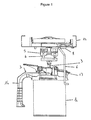
- the device of the present invention will allow the positioning of pot 1 mixer closed by a cover 2 through which protrudes a shaft 3 provided with an agitator, in a rack cabinet.
- This cabinet comprises, integrated with a shelf tray 14, at least one motor device, such as a pulley, driving in displacement of at least one rotary coupling member, said leading 5, arranged to cooperate with a complementary rotary coupling member, said led 4, carried by the portion of the shaft 3 of the mixing pot 1 protruding above the lid 2 of the pot.
- Coupling members leading 5 and led 4 disengageably engage, during the positioning of the pot 1 in the installation, to form an automatic rotating head of the shaft 3 stirrer pot 1 mixer around an axis passing through the axis of rotation of the driving member 5.
- the driving member 5 is in the form of a rotary vane
- the driven member 4 consists of a rotating fork .
- the positioning device is, for its part, essentially consists of a fork with branches in parallel arrangement.
- the so-called active parts 6 of the branches of this fork extend and are maintained substantially parallel to the axis of rotation of the automatic head in the working position of the positioning device.
- These so-called active portions of the branches constitute axial abutments intended to come into bearing contact with the periphery of the lid 2 of the mixer pot 1, during positioning of the pot 1 in the cabinet. This abutment positioning is more particularly visible to figures 1 and 5 .
- These branches form with the axis of rotation of the automatic drive head an isosceles triangle, as illustrated by figure 5 .
- each of the two sides of the same length of the isosceles triangle corresponds substantially to the radius of the lid in which the stirring shaft is centered.
- identical positioning devices for lids of different diameters can be fitted on the same shelf. The design is identical, only the positioning of the device on the shelf bottom varies according to the diameter of the lid.
- the branches of the fork extend at their upper end of connection to the shelf plate 14 by a section 8 substantially perpendicular to the active parts 6 of the branches of the device. At least a portion of this section 8 constitutes a bearing abutment against the bottom of the shelf to limit the angular displacements of the active parts 6 of said branches under the effect of the thrust generated by the introduction of the pot in the space 7 insertion between branches.
- the active portions of the limbs extend substantially parallel to the bottom of the shelf carrying the positioning arrangement.
- the branches are made of a wire material. This results in a simplification of the construction.
- a bridge 11 junction forming a bearing abutment against the shelf bottom 14 and avoids a buckling of said branches. This bridge 11 is more particularly visible at the figure 4 .
- a connecting bridge 12 maintaining the active parts 6 of the branches parallel to each other, in particular under the effect of a thrust generated by the introduction of the pot 1 in the space 7 d inter-branch insertion.
- the lid 2 comprises, opposite its handle 16, on its portion of circular arc intended to be inserted into the inter-branch space 7 of the device, a radial projection constituted, preferably, by the pouring spout 13 of the cover 2. This projection forms in cooperation with the branches of the device an anti-rotation stop of the mixer 1 pot.
- this fork plays both the role of axial abutment of centering member and anti-rotation stop.
- the positioning in a cabinet pots with different lid diameters the device, adapted to be fixed in at least two locations to the tray 14, is coupled in a removable manner said shelf shelf 14 to vary at will the dimensions of the isosceles triangle formed between the branches of the device and axis of the drive head in rotation of the agitator shaft.
- the shelf tray 14 thus comprises at least two receiving locations of the device, each location being chosen according to the dimensions of the lid of the pot or box to be housed in the cabinet.
- the driving member which has the shape of a rotary vane cooperates with the fingers 6 of a fork constituting the driven member 4, is provided with centering guides 15 in the general V-shape to ensure the alignment between the driving elements 5 and 4 led.
- the fork ensures a pre-positioning of the cover equipped with the driven member 4, the final positioning can be provided by the cooperation of the driving member 5 and the driven member 4, due to the presence of centering guides 15 on the driving member 5.
- It may also be provided, in a manner known per se, to incorporate in the connection zone between the driving member 5 and the driven member 6, a torque limiter at least temporarily interrupting the connection between the drive motor device and the agitator shaft of the mixing pot.
- This torque limiter may be constituted by a slot provided at the centering guides 15. This slot widens to be traversed by the finger of the organ 4 conducted beyond the exercise of a predetermined pair.
Landscapes
- Chemical & Material Sciences (AREA)
- Chemical Kinetics & Catalysis (AREA)
- Accessories For Mixers (AREA)
- Mixers Of The Rotary Stirring Type (AREA)
- Mixers With Rotating Receptacles And Mixers With Vibration Mechanisms (AREA)
Priority Applications (1)
| Application Number | Priority Date | Filing Date | Title |
|---|---|---|---|
| PL05798588T PL1784252T3 (pl) | 2004-08-26 | 2005-08-25 | Urządzenie do ustawiania zbiornika mieszalnika w szafie z półkami i szafa wyposażona w takie urządzenie |
Applications Claiming Priority (2)
| Application Number | Priority Date | Filing Date | Title |
|---|---|---|---|
| FR0409123A FR2874512B1 (fr) | 2004-08-26 | 2004-08-26 | Dispositif de positionnement de pot melangeur dans une armoire a etageres et armoire equipee de tels dispositifs |
| PCT/FR2005/002141 WO2006024800A1 (fr) | 2004-08-26 | 2005-08-25 | Dispositif de positionnement de pot melangeur dans une armoire a etageres et armoire equipee de tels dispositifs |
Publications (2)
| Publication Number | Publication Date |
|---|---|
| EP1784252A1 EP1784252A1 (fr) | 2007-05-16 |
| EP1784252B1 true EP1784252B1 (fr) | 2008-07-23 |
Family
ID=34948292
Family Applications (1)
| Application Number | Title | Priority Date | Filing Date |
|---|---|---|---|
| EP05798588A Expired - Lifetime EP1784252B1 (fr) | 2004-08-26 | 2005-08-25 | Dispositif de positionnement de pot melangeur dans une armoire a etageres et armoire equipee de tels dispositifs |
Country Status (6)
| Country | Link |
|---|---|
| EP (1) | EP1784252B1 (pl) |
| CN (1) | CN100503025C (pl) |
| DE (1) | DE602005008447D1 (pl) |
| FR (1) | FR2874512B1 (pl) |
| PL (1) | PL1784252T3 (pl) |
| WO (1) | WO2006024800A1 (pl) |
Cited By (1)
| Publication number | Priority date | Publication date | Assignee | Title |
|---|---|---|---|---|
| CN105249830A (zh) * | 2015-11-26 | 2016-01-20 | 广东新宝电器股份有限公司 | 一种智能暖奶器 |
Families Citing this family (5)
| Publication number | Priority date | Publication date | Assignee | Title |
|---|---|---|---|---|
| USRE39732E1 (en) * | 1995-12-08 | 2007-07-17 | Fillon Investissement | Driving head for stirrer cans |
| WO2003045707A1 (fr) * | 2001-11-30 | 2003-06-05 | F.A.S. | Machine d'agitation de peinture et son procede de montage |
| FR2932697B1 (fr) * | 2008-06-20 | 2011-06-10 | Fillon Technologies | Dispositif d'agitation et son procede de reglage |
| FR3092771B1 (fr) * | 2019-02-15 | 2021-02-12 | Fillon Technologies | Meuble pour l’agitation du contenu de pots mélangeurs |
| CN114789008B (zh) * | 2022-06-23 | 2022-09-02 | 深圳澳睿新能源科技有限公司 | 一种锂电池正极材料加工生产装置 |
Family Cites Families (4)
| Publication number | Priority date | Publication date | Assignee | Title |
|---|---|---|---|---|
| US5358153A (en) * | 1991-12-30 | 1994-10-25 | E. I. Du Pont De Nemours And Company | Mixing lid including a pouring device for containers used on stirring machines |
| US5368389A (en) * | 1992-06-22 | 1994-11-29 | Dedoes Industries, Inc. | Paint can cover assembly |
| FR2742072B1 (fr) * | 1995-12-08 | 1998-01-16 | Fillon Pichon Sa | Tete d'entrainement pour pots agitateurs |
| FR2785953B1 (fr) * | 1998-11-17 | 2000-12-29 | Fillon Pichon Sa | Installation pour l'agitation du contenu, tel que de la peinture, de pots melangeurs |
-
2004
- 2004-08-26 FR FR0409123A patent/FR2874512B1/fr not_active Expired - Fee Related
-
2005
- 2005-08-25 WO PCT/FR2005/002141 patent/WO2006024800A1/fr not_active Ceased
- 2005-08-25 EP EP05798588A patent/EP1784252B1/fr not_active Expired - Lifetime
- 2005-08-25 DE DE602005008447T patent/DE602005008447D1/de not_active Expired - Lifetime
- 2005-08-25 PL PL05798588T patent/PL1784252T3/pl unknown
- 2005-08-25 CN CNB2005800287087A patent/CN100503025C/zh not_active Expired - Fee Related
Cited By (2)
| Publication number | Priority date | Publication date | Assignee | Title |
|---|---|---|---|---|
| CN105249830A (zh) * | 2015-11-26 | 2016-01-20 | 广东新宝电器股份有限公司 | 一种智能暖奶器 |
| CN105249830B (zh) * | 2015-11-26 | 2018-01-09 | 广东新宝电器股份有限公司 | 一种智能暖奶器 |
Also Published As
| Publication number | Publication date |
|---|---|
| FR2874512B1 (fr) | 2006-11-17 |
| CN100503025C (zh) | 2009-06-24 |
| WO2006024800A1 (fr) | 2006-03-09 |
| DE602005008447D1 (de) | 2008-09-04 |
| FR2874512A1 (fr) | 2006-03-03 |
| PL1784252T3 (pl) | 2009-04-30 |
| CN101014405A (zh) | 2007-08-08 |
| EP1784252A1 (fr) | 2007-05-16 |
Similar Documents
| Publication | Publication Date | Title |
|---|---|---|
| EP0778080B1 (fr) | Tête d'entraínement et couvercle pour pots agitateurs | |
| FR2485117A1 (pl) | ||
| EP1784252B1 (fr) | Dispositif de positionnement de pot melangeur dans une armoire a etageres et armoire equipee de tels dispositifs | |
| EP3469970A1 (fr) | Porte-lame pour robot ménager de cuisine | |
| EP0461326B1 (fr) | Dispositif limiteur de couples pour centre modulaire de mélangeage, notamment pour peintures et produits analogues | |
| FR2601871A1 (fr) | Porte-outil dentaire | |
| EP3226731B1 (fr) | Appareil de cuisson à air chaud | |
| FR3048599A1 (fr) | Pied de mixage comprenant un arbre d'entrainement destine a etre entraine en rotation par un boitier moteur | |
| FR3069143A1 (fr) | Un plateau support d'un outil pour appareil de preparation culinaire et appareil de preparation culinaire le comportant | |
| EP1870602B1 (fr) | Pièce d'assemblage de deux éléments entre eux, dispositif d'assemblage associé et application au domaine de l'automobile | |
| FR3058305B1 (fr) | Dispositif de traitement d'aliments muni d'un pied d'appui | |
| FR3058307B1 (fr) | Dispositif de traitement d'aliments cooperant avec plusieurs recipients de cuisson | |
| EP3320818B1 (fr) | Dispositif de traitement d'aliments muni d'un système de fixation d'un outil | |
| EP2058531B1 (fr) | Dispositif de fixation d'une première pièce sur une seconde pièce, telle qu'un panneau | |
| EP1483996B1 (fr) | Accesoire de travail rotatif pour appareil electromenager de preparation culinaire | |
| EP2392750A1 (fr) | Attache volante de support et de fixation d'une structure sur une paroi, munie d'un adaptateur | |
| WO2020165539A1 (fr) | Meuble pour l'agitation du contenu de pots mélangeurs | |
| FR3069507B1 (fr) | Ensemble maneton-manivelle d'un mecanisme de transmission de mouvement d'un systeme d'essuie-glace | |
| FR2575251A1 (fr) | Embrayage a friction | |
| FR2715819A3 (fr) | Robot ménager comportant une pièce auxiliaire avec accouplement à autoemboîtement, ainsi qu'un accouplement et une pièce d'accouplement convenant pour être utilisés dans un tel robot ménager. | |
| EP1566130A1 (fr) | Appareil electromenager de preparation culinaire | |
| EP3063419B1 (fr) | Bague anti-desserrage d'un ecrou | |
| WO2019106269A1 (fr) | Installation pour l'agitation du contenu de pots melangeurs fermes par un couvercle a travers lequel fait saillie un arbre muni d'un agitateur | |
| FR3140527A1 (fr) | Appareil culinaire comprenant un élément de guidage d’une pale de brassage | |
| FR2858029A1 (fr) | Ecrou a grande flottabilite |
Legal Events
| Date | Code | Title | Description |
|---|---|---|---|
| PUAI | Public reference made under article 153(3) epc to a published international application that has entered the european phase |
Free format text: ORIGINAL CODE: 0009012 |
|
| 17P | Request for examination filed |
Effective date: 20070201 |
|
| AK | Designated contracting states |
Kind code of ref document: A1 Designated state(s): DE FR GB IT PL |
|
| 17Q | First examination report despatched |
Effective date: 20070605 |
|
| RBV | Designated contracting states (corrected) |
Designated state(s): DE FR GB IT PL |
|
| DAX | Request for extension of the european patent (deleted) | ||
| GRAP | Despatch of communication of intention to grant a patent |
Free format text: ORIGINAL CODE: EPIDOSNIGR1 |
|
| GRAS | Grant fee paid |
Free format text: ORIGINAL CODE: EPIDOSNIGR3 |
|
| GRAA | (expected) grant |
Free format text: ORIGINAL CODE: 0009210 |
|
| AK | Designated contracting states |
Kind code of ref document: B1 Designated state(s): DE FR GB IT PL |
|
| REG | Reference to a national code |
Ref country code: GB Ref legal event code: FG4D Free format text: NOT ENGLISH |
|
| REF | Corresponds to: |
Ref document number: 602005008447 Country of ref document: DE Date of ref document: 20080904 Kind code of ref document: P |
|
| REG | Reference to a national code |
Ref country code: PL Ref legal event code: T3 |
|
| PLBE | No opposition filed within time limit |
Free format text: ORIGINAL CODE: 0009261 |
|
| STAA | Information on the status of an ep patent application or granted ep patent |
Free format text: STATUS: NO OPPOSITION FILED WITHIN TIME LIMIT |
|
| 26N | No opposition filed |
Effective date: 20090424 |
|
| PG25 | Lapsed in a contracting state [announced via postgrant information from national office to epo] |
Ref country code: IT Free format text: LAPSE BECAUSE OF FAILURE TO SUBMIT A TRANSLATION OF THE DESCRIPTION OR TO PAY THE FEE WITHIN THE PRESCRIBED TIME-LIMIT Effective date: 20080723 |
|
| PGFP | Annual fee paid to national office [announced via postgrant information from national office to epo] |
Ref country code: DE Payment date: 20130821 Year of fee payment: 9 |
|
| PGFP | Annual fee paid to national office [announced via postgrant information from national office to epo] |
Ref country code: GB Payment date: 20130821 Year of fee payment: 9 Ref country code: FR Payment date: 20130823 Year of fee payment: 9 Ref country code: PL Payment date: 20130816 Year of fee payment: 9 |
|
| REG | Reference to a national code |
Ref country code: DE Ref legal event code: R119 Ref document number: 602005008447 Country of ref document: DE |
|
| GBPC | Gb: european patent ceased through non-payment of renewal fee |
Effective date: 20140825 |
|
| REG | Reference to a national code |
Ref country code: DE Ref legal event code: R119 Ref document number: 602005008447 Country of ref document: DE Effective date: 20150303 |
|
| REG | Reference to a national code |
Ref country code: FR Ref legal event code: ST Effective date: 20150430 |
|
| PG25 | Lapsed in a contracting state [announced via postgrant information from national office to epo] |
Ref country code: DE Free format text: LAPSE BECAUSE OF NON-PAYMENT OF DUE FEES Effective date: 20150303 Ref country code: GB Free format text: LAPSE BECAUSE OF NON-PAYMENT OF DUE FEES Effective date: 20140825 |
|
| PG25 | Lapsed in a contracting state [announced via postgrant information from national office to epo] |
Ref country code: FR Free format text: LAPSE BECAUSE OF NON-PAYMENT OF DUE FEES Effective date: 20140901 |
|
| PG25 | Lapsed in a contracting state [announced via postgrant information from national office to epo] |
Ref country code: PL Free format text: LAPSE BECAUSE OF NON-PAYMENT OF DUE FEES Effective date: 20140825 |
|
| REG | Reference to a national code |
Ref country code: PL Ref legal event code: LAPE |