EP1784577B1 - Verriegelungssensor für ein innen verriegelndes stellglied - Google Patents
Verriegelungssensor für ein innen verriegelndes stellglied Download PDFInfo
- Publication number
- EP1784577B1 EP1784577B1 EP20050777165 EP05777165A EP1784577B1 EP 1784577 B1 EP1784577 B1 EP 1784577B1 EP 20050777165 EP20050777165 EP 20050777165 EP 05777165 A EP05777165 A EP 05777165A EP 1784577 B1 EP1784577 B1 EP 1784577B1
- Authority
- EP
- European Patent Office
- Prior art keywords
- field
- actuator
- emitting device
- lock
- target
- Prior art date
- Legal status (The legal status is an assumption and is not a legal conclusion. Google has not performed a legal analysis and makes no representation as to the accuracy of the status listed.)
- Expired - Lifetime
Links
Images


Classifications
-
- F—MECHANICAL ENGINEERING; LIGHTING; HEATING; WEAPONS; BLASTING
- F15—FLUID-PRESSURE ACTUATORS; HYDRAULICS OR PNEUMATICS IN GENERAL
- F15B—SYSTEMS ACTING BY MEANS OF FLUIDS IN GENERAL; FLUID-PRESSURE ACTUATORS, e.g. SERVOMOTORS; DETAILS OF FLUID-PRESSURE SYSTEMS, NOT OTHERWISE PROVIDED FOR
- F15B15/00—Fluid-actuated devices for displacing a member from one position to another; Gearing associated therewith
- F15B15/20—Other details, e.g. assembly with regulating devices
- F15B15/28—Means for indicating the position, e.g. end of stroke
- F15B15/2807—Position switches, i.e. means for sensing of discrete positions only, e.g. limit switches
-
- B—PERFORMING OPERATIONS; TRANSPORTING
- B64—AIRCRAFT; AVIATION; COSMONAUTICS
- B64C—AEROPLANES; HELICOPTERS
- B64C25/00—Alighting gear
- B64C25/02—Undercarriages
- B64C25/08—Undercarriages non-fixed, e.g. jettisonable
- B64C25/10—Undercarriages non-fixed, e.g. jettisonable retractable, foldable, or the like
- B64C25/18—Operating mechanisms
- B64C25/26—Control or locking systems therefor
- B64C25/28—Control or locking systems therefor with indicating or warning devices
-
- F—MECHANICAL ENGINEERING; LIGHTING; HEATING; WEAPONS; BLASTING
- F15—FLUID-PRESSURE ACTUATORS; HYDRAULICS OR PNEUMATICS IN GENERAL
- F15B—SYSTEMS ACTING BY MEANS OF FLUIDS IN GENERAL; FLUID-PRESSURE ACTUATORS, e.g. SERVOMOTORS; DETAILS OF FLUID-PRESSURE SYSTEMS, NOT OTHERWISE PROVIDED FOR
- F15B15/00—Fluid-actuated devices for displacing a member from one position to another; Gearing associated therewith
- F15B15/20—Other details, e.g. assembly with regulating devices
- F15B15/26—Locking mechanisms
-
- F—MECHANICAL ENGINEERING; LIGHTING; HEATING; WEAPONS; BLASTING
- F15—FLUID-PRESSURE ACTUATORS; HYDRAULICS OR PNEUMATICS IN GENERAL
- F15B—SYSTEMS ACTING BY MEANS OF FLUIDS IN GENERAL; FLUID-PRESSURE ACTUATORS, e.g. SERVOMOTORS; DETAILS OF FLUID-PRESSURE SYSTEMS, NOT OTHERWISE PROVIDED FOR
- F15B15/00—Fluid-actuated devices for displacing a member from one position to another; Gearing associated therewith
- F15B15/20—Other details, e.g. assembly with regulating devices
- F15B15/26—Locking mechanisms
- F15B15/261—Locking mechanisms using positive interengagement, e.g. balls and grooves, for locking in the end positions
-
- Y—GENERAL TAGGING OF NEW TECHNOLOGICAL DEVELOPMENTS; GENERAL TAGGING OF CROSS-SECTIONAL TECHNOLOGIES SPANNING OVER SEVERAL SECTIONS OF THE IPC; TECHNICAL SUBJECTS COVERED BY FORMER USPC CROSS-REFERENCE ART COLLECTIONS [XRACs] AND DIGESTS
- Y10—TECHNICAL SUBJECTS COVERED BY FORMER USPC
- Y10T—TECHNICAL SUBJECTS COVERED BY FORMER US CLASSIFICATION
- Y10T70/00—Locks
- Y10T70/80—Parts, attachments, accessories and adjuncts
- Y10T70/8027—Condition indicators
Definitions
- the present invention provides a sensing arrangement to positively determine the locked or locked status of an internally locking actuator.
- the present invention provides a lock sensor mechanism that may be used in an internally locking actuator used in aircraft landing gear.
- An actuator is a mechanism that causes a device to be adjusted or moved, or turned on or off. Hydraulic actuators are used in aircraft landing gear to extend and retract the landing gear. In general, each actuator includes a cylinder or pressure vessel that contains a piston. The piston extends and retracts through the addition of a working fluid (hydraulic oil or compressed gas). Often it is desirable to add a mechanical lock facility to the actuator such that the piston may be mechanically restrained in either of or both the fully extended position and the fully retracted position. A variety of methods are known in the art to provide the mechanical locking facility - a lock which remains set in the absence of the working fluid. These include, but are not limited to the collet lock and the segment lock.
- a separate, independently movable piston within the primary piston is employed to perform the lock and unlock function.
- This lock piston is typically designed such that when the primary piston is not at either end of its displacement, the working fluid preferentially acts on the primary piston to move it. When the primary piston reaches the end of its displacement, the working fluid then works to displace the lock piston.
- the lock piston moves a plurality of lock segments that are sized to fit in grooves located in the cylinder when the lock segments are radially aligned with the grooves. The lock piston is unable to displace fully unless the lock segments mate with the grooves in the cylinder to achieve a true lock.
- a sensing system is employed to indicate to the pilot and the flight control system of the aircraft that a true, mechanical lock has been achieved.
- the lock piston by virtue of being constrained within the primary piston is by design difficult to sense.
- the location of the lock piston must be somehow communicated outside of the piston and cylinder. This is performed by connecting to the lock piston a pin, which slides through a slot in the primary piston. This pin is generally used to align with and connect to a lock sensing mechanism to indicate whether the actuator is locked or unlocked.
- the lock piston When the lock segments are not located within the external grooves the lock piston is unable to move past the lock segments and the lock indicator pin will not align with or connect to the lock sensing mechanism. When the lock segments are located within the external grooves the internal pressure in the vessel moves the lock piston beyond the lock segments and the lock indicator pin is able to align with and connect to the lock sensing mechanism.
- the sensing mechanism is located in an indicator housing assembly which is located at the end of the actuators side brace.
- a switch lever located in the lock sensing mechanism extends from the indicator housing assembly into the path of the lock mechanism of the actuator piston.
- the lock sensing mechanism is activated when a lock indicator pin, connected to the locking mechanism in the piston, moves the switch lever magnifying a displacement on the other end of the lever. This magnified distance moves a target guide, which moves a target into proximity sensor range.
- the proximity sensors transmit a signal indicating that the piston is fully extended and locked.
- the lock sensing mechanisms that include several mechanical parts may be worn down over time. Additionally, mechanical parts can tail to due to interference from foreign bodies or from general mechanical fatigue. It is therefore preferable to use a sensor that does not include mechanical parts and therefore may reduce the necessity for replacement or maintenance of the parts.
- US 3453937 discloses a hydraulic actuator having a main operating piston and a concentric locking and unlocking piston moveable relative thereto, with the position of the locking piston controlling the extension of locking segments which hold the main operating piston of the actuator in one extreme position.
- the locking piston is connected to the locking segments by dogs which move over-center in the locked position.
- the locking piston has a probe movable therewith and a proximity sensor is located adjacent the locking position of the probe and senses its position to signal switching circuitry to activate indicators of the locked or unlocked condition of the actuator.
- the proximity sensor is located exteriorly of the cylinder for the operating and locking pistons and is illustrated in the form of an electromagnet having a sensing coil about a magnet circuit with an air gap which is decreased by the probe on the locking piston to change the reluctance of the magnetic path and the reactance and impedance of the coil where the body of the actuator is of a dielectric material the proximity sensor may rely on a change on the capacity reactance for its response.
- the present invention provides an aircraft landing gear actuator having an internal lock sensor, according to claim 1.
- the at least one field emitting device may be a proximity sensor.
- the at least one target may be made from metallic material.
- the at least one target may be, for example, ferromagnetic.
- the target is integral with the lock indicator ring, for example the target may be the lock indicator ring or may be mounted on the lock indicator ring.
- a sensor including a second field emitting device located longitudinally from a first field emitting device at a location at which the field emitted from the second field emitting device is spaced from the field emitted from the first field emitting device, the at least one target being operable to move within each emitted field.
- a sensor including a second field emitting device located in the same plane as a first field emitting device and circumferentially located relative to the first field emitting device to space the field emitted from the first field emitting device from the second field emitting device.
- an aircraft landing gear actuator comprising a lock sensor described herein.
- the present invention further provides an actuator comprising a lock sensor described herein.
- an internal lock sensor for use in an actuator the lock sensor comprising at least one field emitting device connected to the actuator and operable to emit a field and to measure a change in the emitted field and at least one target connected to actuator and operable to move into and out of the field emitted by the at least one field emitting device, the at least one target being operable to change the emitted field when located in the field.
- the at least one field emitting device may be a proximity sensor.
- the at least one target may be made from metallic material.
- the at least one target may be, for example, ferromagnetic.
- the target is integral with the lock indicator ring, for example the target may be the lock indicator ring or may be mounted on the lock indicator ring.
- a sensor that includes at least one positioning device for positioning the at least one field emitting device relative to the internal piston.
- the positioning device may be at washer or a shim.
- the at least one positioning device may be integral with the field emitting device and may comprise a washer and flange arrangement or a threading arrangement for altering the position of the field emitting device relative to the internal components of the actuator.
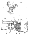
- Figure 1 is a cut away side view of a prior art lock sensing mechanism
- Figure 2 is a cross sectional view of an actuator in which the lock sensor of the present invention may be used;
- Figure 3 is a cross sectional view of the lock sensor of the present invention shown in the locked position
- Figure 4 is a cross sectional view of the lock sensor of the present invention shown in the unlocked position.
- FIGS 5A and B illustrate examples of connecting devices for the field emitting device of the lock sensor of the present invention.
- the lock sensing mechanism 10 includes an indicator housing assembly 12 which contains a switch lever 14, a target guide 16 and a target 18. One end of the switch lever 14 extends out of the indicator housing assembly 12 and into the path of a lock indicator pin, not shown, located on an internal piston in the actuator to which the lock sensing mechanism 10 is attached.
- the use of this type of sensing mechanism 10 is described above in the background of the invention section.
- the actuator 20 includes a piston 22 that is installed within a cylinder assembly 24.
- an internal lock mechanism that includes a plug 26, a lock piston 28, inner and outer springs 30, 32 and various other components that will not be described in detail.
- Lock segments 34 located around the lock piston 28 fit into grooves in the lock piston 28. The lock segments 34 extend when the lock piston 28 moves inside the piston head. When the lock segments 34 are located in the corresponding grooves in the cylinder 24 the piston is locked in the extended position.
- the lock piston 28 moves inside the piston head and a lock indicator pin 41 touches the switch lever 14 when the piston is fully extended which indicates that the actuator is extended and locked.
- hydraulic fluid is supplied to retract the piston the hydraulic pressure will move the lock piston 28 inside the piston.
- the lock piston 28 moves the lock segments retract into the piston head to unlock the piston 22 and the piston retracts.
- the movement of the lock piston 28 moves the lock indicator ring 40 away from the sensing mechanism and a signal that the actuator is unlocked is registered.
- the lock sensor 44 includes at least one field emitting device 46 and at least one target 48.
- the field emitting device 46 is mounted on a locking actuator pressure vessel where it monitors the position of the at least one target 48.
- the at least one target 48 is operable to move into and out of the field produced by the field emitting device 46.
- the at least one field emitting device 46 emits a field that when breached sends a signal to indicate such.
- the breaching of the field may include either a break in the field or a change in a measurement of the emitted field.
- the field emitting device may be an inductance sensor and a breach of the field is indicated by a change in the inductance measurement, for example when a ferromagnetic material moves into the field.
- the field emitting device 46 may be a proximity sensor, such devices are known and commercially available, for example proximity sensors manufactured by Eldec Corporation.
- proximity sensors that may be used in the present invention include, but are not limited to, capacitive, eddy current killed oscillation, inductive, photoelectric, and ultrasonic.
- capacitive proximity sensor the field emitting device would act as one capacitor, and the target will include a conductive surface which will act as the second capacitor.
- the capacitance will vary inversely with the distance between the two capacitors and a pre-set value can be programmed to trigger target detection.
- an eddy current killed oscillation proximity sensor an oscillating magnetic field is emitted by the sensor.
- the sensor In the presence of electrically conductive materials (such as a target) electrical eddy currents are generated.
- the sensor is designed such that the energy induced in the conductive target is sufficient to halt the oscillation of the magnetic field - killing the oscillation.
- the target may be made of metal and when moved into proximity with the field emitting device will cease oscillating thereby indicating a breach of the field.
- Other proximity sensors include photoelectric devices and ultrasonic proximity sensors.
- the at least one field emitting device 46 is mounted on the rod end cap 50 of the side brace 52 of the actuator.
- the at least one field emitting device 46 may be mounted using threads, i.e a screw-type fit. It will be understood that the field emitting device 46 may be mounted by any means known to a person skilled in the art, in a manner that provides a pressure seal. Examples of ways for mounting or attaching the field emitting device 46 to the rod end cap, include but are not limited to, threading the field emitting device into the rod end cap, mounting the field emitting device to the rod end cap using an o-ring and a flange that may be attached to the rod end cap using, for example, bolts or screws, for which examples are illustrated in Figure 5 .
- the target 48 is integral with the lock indicator ring 24.
- the lock indicator ring 24 is manufactured from a material that will induce a change in the field emitted from the field emitting device 46 when placed within the emitted field. In this manner the lock indicator ring 24 becomes the target 48.
- the target i.e. the lock indicator ring 24
- the lock indicator ring 24 may be made from a metal material that will change the inductance measurement when it enters the field.
- the lock indicator ring 24 may be made from a ferrous material.
- the target 48 may be mounted on to the lock indicator ring 24 and formed from different material than the lock indicator ring 24.
- the target 48 may be made from a ferrous material and mounted, either partially or completely around the external periphery of the lock indicator ring 24. It will be understood that the mounting of the target 48 should be located on the lock indicator ring 24 at least at a position that will be within the range of the emitted field when the lock indicator ring 24 is located within the plane of the field.
- the position for the mounting of the target 48 is chosen so that in the unlocked position the target 48 is not located within the field emitted by the field emitting device 46 and is located at a position outside of the field emitting device 46 sensing range.
- the actuator 20 is in the locked position the target 48 moves within the field, either completely or partially so that the field is interrupted and the field emitting device 46 can identify that the field has been interrogated.
- the target 48 may be mounted directly on the lock piston 28. In this arrangement the mounting of the target 48 to the lock piston 28 may replace the lock indicator ring.
- the target 48 will be mounted on the lock piston 28 at a location that is operable to move into and out of the field. It will be understood that the position of the target 48 in this embodiment will be chosen in order to fulfill the requirements of the disclosed invention.
- the field emitting device 46 Due to production tolerances of the components in the actuator, it is preferable to provide axial adjustment of the field emitting device 46 in order to calibrate (rig) the field emitting device 46 for standard operation.
- the ability to provide axial adjustment allows field interchangeability of the actuator unit. In the embodiments described herein, this adjustment can be made at the attachment point of the field emitting device 46 to the end cap of the side brace. For example, if the field emitting device 46 is threaded onto the side brace then the axial adjustment may be made by releasing the threading attachment of the device 46 to the end cap, i.e. unscrewing the field emitting device or screwing the field emitting device to change the radial location of the field relative to the internal components of the actuator..
- washers and/or shims may be included in the attachment of the field emitting device in order to change the radial position thereof.
- the field emitting device 46 of the present invention will be chosen in order that it can withstand the pressure requirements of the actuator.
- the attachment of the field emitting device 46 must provide a pressure seal at the point of attachment to the end cap of the side brace.
- the lock sensor of the present invention When the lock sensor of the present invention is used in an actuator located in an aircraft landing gear application preferably the lock sensor includes two or more field emitting devices 46.
- the inclusion of an additional field emitting device 46 provides a back up to the system in case of failure of one of the field emitting devices 46.
- the landing gear application it is preferable to have a back up to ensure that a measurement is taken to indicate to the pilot of the aircraft whether the actuator system is in the locked or unlocked position.
- the lock sensor 44 may include two or more field emitting devices 46 located within the same circumferential plane.
- the target 48 i.e. the lock indicator ring
- each field emitting device 46 identifies the presence of the target 48 and more than one indication of the actuator being in the locked position is made.
- This embodiment provides one example of a system that includes a back up measurement.
- An alternative embodiment in which two field emitting devices 46 are included may position a second field emitting device 46 longitudinally spaced along the axis of the actuator from the first field emitting device 46.
- the two field emitting devices 46 may be positioned so that when the actuator is in the locked position the target 48 is located within the field of the first field emitting devices 46. When the actuator is in the unlocked position the target 48 will be located within the field of the second field emitting device 48.
- the at least one field emitting device 48 is located adjacent the lock segments 26 and the at least one target 48 is integral with or attached to one or more of the lock segments 26.
- the field emitted by the at least one field emitting device 46 extends a predetermined distance radially inwards from the periphery of the actuator.
- the field emitting devices 46 in this embodiment will be designed so that the field emitted does not radially extend within reach of being breached by the lock segment 26 containing the target 48 when they are in the unlocked position. This means that when the lock segments 26 are not located in the grooves of the piston they do not breach the field emitted by the at least one field emitting device 46. However, when the lock segments 26 are located in the grooves in the locked position the field is breached and an indication that the actuator is locked is made.
- the field emitting device 46 may be operable to only record a change in the field emitted therefrom.
- the field emitting device 46 may be capable of analysing the recorded change or transmitting the recorded change to a control system located on or near the actuator so that the reporting of or manipulation of the reading is performed by the control system. Any recorded change in the field will be used to send an indication to the pilot, when used in aircraft landing gear, to indicate that the system is in the locked or unlocked position.
- This pressure is greater than the lock spring pressure causing the lock piston 22 to move back. By doing so the lock segments 26 collapse within the piston head pulling the lock indicating ring 24 back toward the cylinder.
- the inductance drops to less than or equal to second predetermined measurement, for example 4.89 mH, transmitting a signal indicating the piston is fully unlocked.
Landscapes
- Engineering & Computer Science (AREA)
- Mechanical Engineering (AREA)
- Physics & Mathematics (AREA)
- Fluid Mechanics (AREA)
- General Engineering & Computer Science (AREA)
- Aviation & Aerospace Engineering (AREA)
- Measuring Fluid Pressure (AREA)
- Actuator (AREA)
- Mechanical Control Devices (AREA)
- Transmission Devices (AREA)
- Measurement Of Length, Angles, Or The Like Using Electric Or Magnetic Means (AREA)
- Orthopedics, Nursing, And Contraception (AREA)
Claims (15)
- Betätigungselement (20) für ein Flugzeug-Fahrwerk mit einem internen Verriegelungssensor (10), wobei der Verriegelungssensor Folgendes umfasst:i. mindestens eine Feldemissionsvorrichtung (46), die an einem Betätigungselement-Druckgefäß angebracht ist, um eine Druckdichtung vorzusehen, um Druckanforderungen des Betätigungselements zu widerstehen und die wirksam ist, um ein Feld zu emittieren und eine Änderung des emittierten Felds zu messen; undii. mindestens ein Ziel (48), das mit dem Betätigungselement (20) verbunden ist und wirksam ist, um sich in das von der mindestens einen Feldemissionsvorrichtung emittierte Feld und daraus heraus zu bewegen, wobei das mindestens eine Ziel wirksam ist, um das emittierte Feld zu verändern, wenn es sich in dem Feld befindet.
- Betätigungselement (20) nach Anspruch 1, das einen mit einem Verriegelungsanzeigering (40) verbundenen innenliegenden Kolben (22) aufweist und mindestens ein damit verbundenes Verriegelungssegment (34) aufweist, wobei das mindestens eine Ziel (48) mit dem innenliegenden Kolben verbunden ist.
- Betätigungselement (20) nach Anspruch 2, wobei sich der Verriegelungsanzeigering (40) an dem Betätigungselement befindet.
- Betätigungselement (20) nach Anspruch 2 oder Anspruch 3, wobei das mindestens eine Ziel einstückig mit dem Verriegelungsanzeigering ausgebildet ist.
- Betätigungselement (20) nach Anspruch 4, wobei es sich bei dem mindestens einen Ziel (48) um den Verriegelungsanzeigering (40) handelt.
- Betätigungselement (20) nach Anspruch 2 oder Anspruch 3, wobei das mindestens eine Ziel (48) an dem Verriegelungsanzeigering (40) angebracht ist.
- Betätigungselement (20) nach Anspruch 2 oder Anspruch 3, wobei das mindestens eine Ziel (48) an dem innenliegenden Kolben (22) des Betätigungselements (20) angebracht ist.
- Betätigungselement (20) nach einem der Ansprüche 2 bis 7, weiter umfassend mindestens eine Positionierungsvorrichtung zum Positionieren der mindestens einen Feldemissionsvorrichtung (48) relativ zu dem innenliegenden Kolben (22).
- Betätigungselement (20) nach einem der Ansprüche 1 bis 8, wobei es sich bei der mindestens einen Feldemissionsvorrichtung (46) um einen Näherungssensor handelt.
- Betätigungselement (20) nach einem der Ansprüche 1 bis 9, wobei es sich bei dem mindestens einen Ziel (48) um ein Metallmaterial handelt.
- Betätigungselement (20) nach einem der Ansprüche 1 bis 10, wobei das mindestens eine Ziel (48) ferromagnetisch ist.
- Betätigungselement (20) nach einem der Ansprüche 1 bis 11, weiter umfassend eine zweite Feldemissionsvorrichtung, die sich in Längsrichtung von einer ersten Feldemissionsvorrichtung entfernt an einem Ort befindet, an dem das von der zweiten Feldemissionsvorrichtung emittierte Feld von dem von der ersten Feldemissionsvorrichtung (46) emittieren Feld beabstandet ist, wobei das mindestens eine Ziel (48) wirksam ist, um sich innerhalb von jedem emittierten Feld zu bewegen.
- Betätigungselement (20)-Verriegelungssensor nach einem der Ansprüche 1 bis 11, weiter umfassend eine zweite Feldemissionsvorrichtung, die sich in der selben Ebene befindet wie eine erste Feldemissionsvorrichtung (46) und sich derart in Umfangsrichtung relativ zu der ersten Feldemissionsvorrichtung befindet, dass das von der ersten Feldemissionsvorrichtung emittierte Feld von der zweite Feldemissionsvorrichtung beabstandet ist.
- Betätigungselement (20) nach einem der Ansprüche 1 bis 13, wobei sich die mindestens eine Feldemissionsvorrichtung (46) an einer Seitenstrebe des Betätigungselements (20) befindet.
- Verfahren, das an einem Flugzeug verwendet wird, um den Zustand eines Verriegelungssensors (22) in einem Betätigungselement (20) eines Flugzeug-Fahrwerks anzuzeigen, wobei der Verriegelungssensor mindestens eine Feldemissionsvorrichtung (46) aufweist, die an einem Betätigungselement-Druckgefäß angebracht ist, um eine Druckdichtung bereitzustellen, um Druckanforderungen des Betätigungselements zu widerstehen und ein Ziel (48) aufweist, das wirksam ist, um sich in das von der Feldemissionsvorrichtung emittierte Feld hinein und daraus hinaus zu bewegen, wobei das Verfahren folgende Schritte umfasst:i. Emittieren eines Felds von der mindestens einen Feldemissionsvorrichtung;ii. Messen des emittierten Felds; undiii. Melden jeder Änderung des emittierten Felds.
Applications Claiming Priority (2)
| Application Number | Priority Date | Filing Date | Title |
|---|---|---|---|
| CA002479454A CA2479454A1 (en) | 2004-08-30 | 2004-08-30 | Internally locking actuator with direct acting integral lock sensor |
| PCT/CA2005/001303 WO2006024145A1 (en) | 2004-08-30 | 2005-08-30 | Lock sensor for an internally locking actuator |
Publications (3)
| Publication Number | Publication Date |
|---|---|
| EP1784577A1 EP1784577A1 (de) | 2007-05-16 |
| EP1784577A4 EP1784577A4 (de) | 2010-04-14 |
| EP1784577B1 true EP1784577B1 (de) | 2013-11-20 |
Family
ID=35997693
Family Applications (1)
| Application Number | Title | Priority Date | Filing Date |
|---|---|---|---|
| EP20050777165 Expired - Lifetime EP1784577B1 (de) | 2004-08-30 | 2005-08-30 | Verriegelungssensor für ein innen verriegelndes stellglied |
Country Status (6)
| Country | Link |
|---|---|
| US (1) | US20090091476A1 (de) |
| EP (1) | EP1784577B1 (de) |
| BR (1) | BRPI0514616A (de) |
| CA (1) | CA2479454A1 (de) |
| ES (1) | ES2445338T3 (de) |
| WO (1) | WO2006024145A1 (de) |
Families Citing this family (9)
| Publication number | Priority date | Publication date | Assignee | Title |
|---|---|---|---|---|
| US7642125B2 (en) * | 2007-09-14 | 2010-01-05 | Macronix International Co., Ltd. | Phase change memory cell in via array with self-aligned, self-converged bottom electrode and method for manufacturing |
| GB2466223A (en) * | 2008-12-15 | 2010-06-16 | Robert John Sykes | Aircraft ground lock detection device. |
| CN102734262B (zh) * | 2012-07-12 | 2014-12-24 | 中联重科股份有限公司 | 驱动缸及具有该驱动缸的起重机和工程机械 |
| US20150167702A1 (en) * | 2013-12-12 | 2015-06-18 | Triumph Actuation Systems - Yakima, LLC | Actuator assemblies |
| CN104632787B (zh) * | 2015-02-12 | 2016-11-30 | 中航飞机起落架有限责任公司 | 一种作动筒内置机械锁锁定状态的自检测机构 |
| EP3109487A1 (de) | 2015-06-26 | 2016-12-28 | SPP Canada Aircraft, Inc. | Duales hydraulisches verriegelungsstellglied für eine strukturstütze |
| CA2895679C (en) | 2015-06-26 | 2017-12-12 | V-Bond Lee | Dual locking hydraulic actuator for structural brace |
| GB2575772A (en) * | 2018-05-22 | 2020-01-29 | Airbus Operations Ltd | System for detecting uplock system integrity |
| DE202022100277U1 (de) | 2022-01-19 | 2023-04-21 | Liebherr-Aerospace Lindenberg Gmbh | Verriegelungserfassungseinrichtung |
Family Cites Families (11)
| Publication number | Priority date | Publication date | Assignee | Title |
|---|---|---|---|---|
| US3177780A (en) * | 1963-05-27 | 1965-04-13 | Roger K Andersen | Locking cylinder |
| US3415167A (en) * | 1966-10-20 | 1968-12-10 | Whitney J. Champagne | Locking cylinder |
| US3453937A (en) | 1967-09-14 | 1969-07-08 | Lionel Pacific Inc | Hydraulic actuator with proximity sensor of locked condition |
| JPS52154976A (en) * | 1976-06-18 | 1977-12-23 | Teijin Seiki Co Ltd | Actuator |
| DE3525029C2 (de) * | 1984-12-22 | 1995-08-31 | Festo Kg | Kolben-Zylinder-Anordnung |
| DE3708989C2 (de) * | 1987-03-19 | 1993-10-14 | Festo Kg | Steuervorrichtung für einen in einem doppeltwirkenden Zylinder verschiebbaren Kolben |
| JPH02292504A (ja) * | 1989-05-01 | 1990-12-04 | Teijin Seiki Co Ltd | ロック機構付液圧アクチュエータ |
| JP2631081B2 (ja) * | 1994-01-18 | 1997-07-16 | ダウティ エアロスペース グロスター リミテッド | 車輪昇降用の作動シリンダ |
| JP3671198B2 (ja) * | 1997-06-13 | 2005-07-13 | ナブテスコ株式会社 | 航空機用脚昇降装置 |
| US6299426B1 (en) * | 1999-06-25 | 2001-10-09 | Pfa Incorporated | Mold and die casting apparatus including a compact core position sensor unit having magnetic switches |
| US6487846B1 (en) * | 2001-09-07 | 2002-12-03 | Honeywell International, Inc. | Thrust reverser actuator including an integrated locking mechanism |
-
2004
- 2004-08-30 CA CA002479454A patent/CA2479454A1/en not_active Abandoned
-
2005
- 2005-08-30 BR BRPI0514616-0A patent/BRPI0514616A/pt not_active IP Right Cessation
- 2005-08-30 WO PCT/CA2005/001303 patent/WO2006024145A1/en not_active Ceased
- 2005-08-30 EP EP20050777165 patent/EP1784577B1/de not_active Expired - Lifetime
- 2005-08-30 ES ES05777165T patent/ES2445338T3/es not_active Expired - Lifetime
- 2005-08-30 US US11/573,215 patent/US20090091476A1/en not_active Abandoned
Also Published As
| Publication number | Publication date |
|---|---|
| ES2445338T3 (es) | 2014-03-03 |
| US20090091476A1 (en) | 2009-04-09 |
| EP1784577A4 (de) | 2010-04-14 |
| CA2479454A1 (en) | 2006-02-28 |
| BRPI0514616A (pt) | 2008-06-17 |
| EP1784577A1 (de) | 2007-05-16 |
| WO2006024145A1 (en) | 2006-03-09 |
Similar Documents
| Publication | Publication Date | Title |
|---|---|---|
| US9303713B2 (en) | Piston-cylinder unit | |
| EP3126226B1 (de) | System zur erkennung der mechanischen trennung eines sensors von einem gesteuerten element | |
| US20090091476A1 (en) | Lock sensor for an internally locking actuator | |
| CN104295540B (zh) | 带气体泄漏报警装置的蓄能器及液压操动机构 | |
| US20100127695A1 (en) | Inductive sensors | |
| CN102419185B (zh) | 用于检测销上的负载的电容传感器 | |
| CN107810388B (zh) | 具有故障检测单元的模块化密封设备 | |
| US7788983B2 (en) | Sensor arrangement | |
| US20100050863A1 (en) | Fluid-powered actuator having an internal position sensor and a sensor module therefor | |
| US8721238B2 (en) | Tool clamping device | |
| DE102015114205A1 (de) | Wegmessverfahren für einen magnetischen Sensor und Sensor | |
| US3453937A (en) | Hydraulic actuator with proximity sensor of locked condition | |
| CA2576801C (en) | Lock sensor for an internally locking actuator | |
| CN109000550B (zh) | 线圈磁场屏蔽式接近传感器 | |
| CN114729655A (zh) | 流体压力缸 | |
| US20070145969A1 (en) | Long stroke hall position sensor having a shaped pole | |
| EP1024300A2 (de) | Anordnung zum Einbau eines Sensors | |
| CN101949401B (zh) | 油缸行程检测装置、液压系统及具有该系统的工程机械 | |
| US4206455A (en) | Piston overtravel indicator | |
| EP3296603B1 (de) | Ventilaufsatz, ventil und verfahren zur steuerung eines ventils | |
| CN216353950U (zh) | 一种液压系统压力继电器 | |
| WO2014092635A1 (en) | Piston-cylinder device and method for detecting axial position | |
| CN219570477U (zh) | 一种带位置检测的电液换向阀 | |
| CN223019595U (zh) | 电磁球阀及阀门控制系统 | |
| CN110836211A (zh) | 带锁定指示器的可锁定线性致动器 |
Legal Events
| Date | Code | Title | Description |
|---|---|---|---|
| PUAI | Public reference made under article 153(3) epc to a published international application that has entered the european phase |
Free format text: ORIGINAL CODE: 0009012 |
|
| 17P | Request for examination filed |
Effective date: 20070130 |
|
| AK | Designated contracting states |
Kind code of ref document: A1 Designated state(s): AT BE BG CH CY CZ DE DK EE ES FI FR GB GR HU IE IS IT LI LT LU LV MC NL PL PT RO SE SI SK TR |
|
| DAX | Request for extension of the european patent (deleted) | ||
| A4 | Supplementary search report drawn up and despatched |
Effective date: 20100311 |
|
| 17Q | First examination report despatched |
Effective date: 20100702 |
|
| GRAP | Despatch of communication of intention to grant a patent |
Free format text: ORIGINAL CODE: EPIDOSNIGR1 |
|
| INTG | Intention to grant announced |
Effective date: 20130603 |
|
| GRAS | Grant fee paid |
Free format text: ORIGINAL CODE: EPIDOSNIGR3 |
|
| GRAA | (expected) grant |
Free format text: ORIGINAL CODE: 0009210 |
|
| AK | Designated contracting states |
Kind code of ref document: B1 Designated state(s): AT BE BG CH CY CZ DE DK EE ES FI FR GB GR HU IE IS IT LI LT LU LV MC NL PL PT RO SE SI SK TR |
|
| REG | Reference to a national code |
Ref country code: GB Ref legal event code: FG4D |
|
| REG | Reference to a national code |
Ref country code: DE Ref legal event code: R081 Ref document number: 602005041938 Country of ref document: DE Owner name: SAFRAN LANDING SYSTEMS CANADA INC. / SAFRAN SY, CA Free format text: FORMER OWNER: MESSIER-DOWTY, INC., AJAX, ONTARIO, CA |
|
| REG | Reference to a national code |
Ref country code: CH Ref legal event code: EP |
|
| REG | Reference to a national code |
Ref country code: AT Ref legal event code: REF Ref document number: 641819 Country of ref document: AT Kind code of ref document: T Effective date: 20131215 |
|
| REG | Reference to a national code |
Ref country code: IE Ref legal event code: FG4D |
|
| REG | Reference to a national code |
Ref country code: DE Ref legal event code: R096 Ref document number: 602005041938 Country of ref document: DE Effective date: 20140116 |
|
| REG | Reference to a national code |
Ref country code: ES Ref legal event code: FG2A Ref document number: 2445338 Country of ref document: ES Kind code of ref document: T3 Effective date: 20140303 |
|
| REG | Reference to a national code |
Ref country code: NL Ref legal event code: VDEP Effective date: 20131120 |
|
| REG | Reference to a national code |
Ref country code: AT Ref legal event code: MK05 Ref document number: 641819 Country of ref document: AT Kind code of ref document: T Effective date: 20131120 |
|
| REG | Reference to a national code |
Ref country code: LT Ref legal event code: MG4D |
|
| PG25 | Lapsed in a contracting state [announced via postgrant information from national office to epo] |
Ref country code: SE Free format text: LAPSE BECAUSE OF FAILURE TO SUBMIT A TRANSLATION OF THE DESCRIPTION OR TO PAY THE FEE WITHIN THE PRESCRIBED TIME-LIMIT Effective date: 20131120 Ref country code: LT Free format text: LAPSE BECAUSE OF FAILURE TO SUBMIT A TRANSLATION OF THE DESCRIPTION OR TO PAY THE FEE WITHIN THE PRESCRIBED TIME-LIMIT Effective date: 20131120 Ref country code: FI Free format text: LAPSE BECAUSE OF FAILURE TO SUBMIT A TRANSLATION OF THE DESCRIPTION OR TO PAY THE FEE WITHIN THE PRESCRIBED TIME-LIMIT Effective date: 20131120 Ref country code: IS Free format text: LAPSE BECAUSE OF FAILURE TO SUBMIT A TRANSLATION OF THE DESCRIPTION OR TO PAY THE FEE WITHIN THE PRESCRIBED TIME-LIMIT Effective date: 20140320 Ref country code: NL Free format text: LAPSE BECAUSE OF FAILURE TO SUBMIT A TRANSLATION OF THE DESCRIPTION OR TO PAY THE FEE WITHIN THE PRESCRIBED TIME-LIMIT Effective date: 20131120 |
|
| PG25 | Lapsed in a contracting state [announced via postgrant information from national office to epo] |
Ref country code: LV Free format text: LAPSE BECAUSE OF FAILURE TO SUBMIT A TRANSLATION OF THE DESCRIPTION OR TO PAY THE FEE WITHIN THE PRESCRIBED TIME-LIMIT Effective date: 20131120 Ref country code: AT Free format text: LAPSE BECAUSE OF FAILURE TO SUBMIT A TRANSLATION OF THE DESCRIPTION OR TO PAY THE FEE WITHIN THE PRESCRIBED TIME-LIMIT Effective date: 20131120 Ref country code: BE Free format text: LAPSE BECAUSE OF FAILURE TO SUBMIT A TRANSLATION OF THE DESCRIPTION OR TO PAY THE FEE WITHIN THE PRESCRIBED TIME-LIMIT Effective date: 20131120 |
|
| PG25 | Lapsed in a contracting state [announced via postgrant information from national office to epo] |
Ref country code: PT Free format text: LAPSE BECAUSE OF FAILURE TO SUBMIT A TRANSLATION OF THE DESCRIPTION OR TO PAY THE FEE WITHIN THE PRESCRIBED TIME-LIMIT Effective date: 20140320 |
|
| PG25 | Lapsed in a contracting state [announced via postgrant information from national office to epo] |
Ref country code: EE Free format text: LAPSE BECAUSE OF FAILURE TO SUBMIT A TRANSLATION OF THE DESCRIPTION OR TO PAY THE FEE WITHIN THE PRESCRIBED TIME-LIMIT Effective date: 20131120 |
|
| REG | Reference to a national code |
Ref country code: DE Ref legal event code: R097 Ref document number: 602005041938 Country of ref document: DE |
|
| PG25 | Lapsed in a contracting state [announced via postgrant information from national office to epo] |
Ref country code: RO Free format text: LAPSE BECAUSE OF FAILURE TO SUBMIT A TRANSLATION OF THE DESCRIPTION OR TO PAY THE FEE WITHIN THE PRESCRIBED TIME-LIMIT Effective date: 20131120 Ref country code: CZ Free format text: LAPSE BECAUSE OF FAILURE TO SUBMIT A TRANSLATION OF THE DESCRIPTION OR TO PAY THE FEE WITHIN THE PRESCRIBED TIME-LIMIT Effective date: 20131120 Ref country code: PL Free format text: LAPSE BECAUSE OF FAILURE TO SUBMIT A TRANSLATION OF THE DESCRIPTION OR TO PAY THE FEE WITHIN THE PRESCRIBED TIME-LIMIT Effective date: 20131120 Ref country code: SK Free format text: LAPSE BECAUSE OF FAILURE TO SUBMIT A TRANSLATION OF THE DESCRIPTION OR TO PAY THE FEE WITHIN THE PRESCRIBED TIME-LIMIT Effective date: 20131120 |
|
| PLBE | No opposition filed within time limit |
Free format text: ORIGINAL CODE: 0009261 |
|
| STAA | Information on the status of an ep patent application or granted ep patent |
Free format text: STATUS: NO OPPOSITION FILED WITHIN TIME LIMIT |
|
| PG25 | Lapsed in a contracting state [announced via postgrant information from national office to epo] |
Ref country code: DK Free format text: LAPSE BECAUSE OF FAILURE TO SUBMIT A TRANSLATION OF THE DESCRIPTION OR TO PAY THE FEE WITHIN THE PRESCRIBED TIME-LIMIT Effective date: 20131120 |
|
| 26N | No opposition filed |
Effective date: 20140821 |
|
| REG | Reference to a national code |
Ref country code: DE Ref legal event code: R097 Ref document number: 602005041938 Country of ref document: DE Effective date: 20140821 |
|
| PG25 | Lapsed in a contracting state [announced via postgrant information from national office to epo] |
Ref country code: SI Free format text: LAPSE BECAUSE OF FAILURE TO SUBMIT A TRANSLATION OF THE DESCRIPTION OR TO PAY THE FEE WITHIN THE PRESCRIBED TIME-LIMIT Effective date: 20131120 |
|
| PG25 | Lapsed in a contracting state [announced via postgrant information from national office to epo] |
Ref country code: LU Free format text: LAPSE BECAUSE OF FAILURE TO SUBMIT A TRANSLATION OF THE DESCRIPTION OR TO PAY THE FEE WITHIN THE PRESCRIBED TIME-LIMIT Effective date: 20140830 Ref country code: MC Free format text: LAPSE BECAUSE OF FAILURE TO SUBMIT A TRANSLATION OF THE DESCRIPTION OR TO PAY THE FEE WITHIN THE PRESCRIBED TIME-LIMIT Effective date: 20131120 |
|
| REG | Reference to a national code |
Ref country code: CH Ref legal event code: PL |
|
| PG25 | Lapsed in a contracting state [announced via postgrant information from national office to epo] |
Ref country code: LI Free format text: LAPSE BECAUSE OF NON-PAYMENT OF DUE FEES Effective date: 20140831 Ref country code: CH Free format text: LAPSE BECAUSE OF NON-PAYMENT OF DUE FEES Effective date: 20140831 Ref country code: IT Free format text: LAPSE BECAUSE OF FAILURE TO SUBMIT A TRANSLATION OF THE DESCRIPTION OR TO PAY THE FEE WITHIN THE PRESCRIBED TIME-LIMIT Effective date: 20131120 |
|
| REG | Reference to a national code |
Ref country code: IE Ref legal event code: MM4A |
|
| PG25 | Lapsed in a contracting state [announced via postgrant information from national office to epo] |
Ref country code: IE Free format text: LAPSE BECAUSE OF NON-PAYMENT OF DUE FEES Effective date: 20140830 |
|
| REG | Reference to a national code |
Ref country code: ES Ref legal event code: FD2A Effective date: 20150925 |
|
| PG25 | Lapsed in a contracting state [announced via postgrant information from national office to epo] |
Ref country code: ES Free format text: LAPSE BECAUSE OF NON-PAYMENT OF DUE FEES Effective date: 20140831 |
|
| PG25 | Lapsed in a contracting state [announced via postgrant information from national office to epo] |
Ref country code: BG Free format text: LAPSE BECAUSE OF FAILURE TO SUBMIT A TRANSLATION OF THE DESCRIPTION OR TO PAY THE FEE WITHIN THE PRESCRIBED TIME-LIMIT Effective date: 20131120 |
|
| PG25 | Lapsed in a contracting state [announced via postgrant information from national office to epo] |
Ref country code: CY Free format text: LAPSE BECAUSE OF FAILURE TO SUBMIT A TRANSLATION OF THE DESCRIPTION OR TO PAY THE FEE WITHIN THE PRESCRIBED TIME-LIMIT Effective date: 20131120 Ref country code: GR Free format text: LAPSE BECAUSE OF FAILURE TO SUBMIT A TRANSLATION OF THE DESCRIPTION OR TO PAY THE FEE WITHIN THE PRESCRIBED TIME-LIMIT Effective date: 20140221 |
|
| REG | Reference to a national code |
Ref country code: FR Ref legal event code: PLFP Year of fee payment: 12 |
|
| PG25 | Lapsed in a contracting state [announced via postgrant information from national office to epo] |
Ref country code: HU Free format text: LAPSE BECAUSE OF FAILURE TO SUBMIT A TRANSLATION OF THE DESCRIPTION OR TO PAY THE FEE WITHIN THE PRESCRIBED TIME-LIMIT; INVALID AB INITIO Effective date: 20050830 Ref country code: TR Free format text: LAPSE BECAUSE OF FAILURE TO SUBMIT A TRANSLATION OF THE DESCRIPTION OR TO PAY THE FEE WITHIN THE PRESCRIBED TIME-LIMIT Effective date: 20131120 |
|
| REG | Reference to a national code |
Ref country code: DE Ref legal event code: R081 Ref document number: 602005041938 Country of ref document: DE Owner name: SAFRAN LANDING SYSTEMS CANADA INC. / SAFRAN SY, CA Free format text: FORMER OWNER: MESSIER-DOWTY, INC., AJAX, ONTARIO, CA Ref country code: DE Ref legal event code: R082 Ref document number: 602005041938 Country of ref document: DE Representative=s name: DF-MP DOERRIES FRANK-MOLNIA & POHLMAN PATENTAN, DE |
|
| REG | Reference to a national code |
Ref country code: FR Ref legal event code: CD Owner name: SAFRAN LANDING SYSTEMS CANADA INC./SAFRAN SYST, CA Effective date: 20170301 |
|
| REG | Reference to a national code |
Ref country code: FR Ref legal event code: PLFP Year of fee payment: 13 |
|
| REG | Reference to a national code |
Ref country code: FR Ref legal event code: PLFP Year of fee payment: 14 |
|
| PGFP | Annual fee paid to national office [announced via postgrant information from national office to epo] |
Ref country code: GB Payment date: 20220721 Year of fee payment: 18 Ref country code: DE Payment date: 20220616 Year of fee payment: 18 |
|
| REG | Reference to a national code |
Ref country code: DE Ref legal event code: R119 Ref document number: 602005041938 Country of ref document: DE |
|
| GBPC | Gb: european patent ceased through non-payment of renewal fee |
Effective date: 20230830 |
|
| PG25 | Lapsed in a contracting state [announced via postgrant information from national office to epo] |
Ref country code: GB Free format text: LAPSE BECAUSE OF NON-PAYMENT OF DUE FEES Effective date: 20230830 |
|
| PG25 | Lapsed in a contracting state [announced via postgrant information from national office to epo] |
Ref country code: GB Free format text: LAPSE BECAUSE OF NON-PAYMENT OF DUE FEES Effective date: 20230830 Ref country code: DE Free format text: LAPSE BECAUSE OF NON-PAYMENT OF DUE FEES Effective date: 20240301 |
|
| PGFP | Annual fee paid to national office [announced via postgrant information from national office to epo] |
Ref country code: FR Payment date: 20240723 Year of fee payment: 20 |