EP1785162A2 - Dispositif d'attribution de rayonnement et procédé d'attribution de rayonnement pour accélérateur de particules médical - Google Patents
Dispositif d'attribution de rayonnement et procédé d'attribution de rayonnement pour accélérateur de particules médical Download PDFInfo
- Publication number
- EP1785162A2 EP1785162A2 EP07004468A EP07004468A EP1785162A2 EP 1785162 A2 EP1785162 A2 EP 1785162A2 EP 07004468 A EP07004468 A EP 07004468A EP 07004468 A EP07004468 A EP 07004468A EP 1785162 A2 EP1785162 A2 EP 1785162A2
- Authority
- EP
- European Patent Office
- Prior art keywords
- irradiation
- room
- spill
- allocation device
- control
- Prior art date
- Legal status (The legal status is an assumption and is not a legal conclusion. Google has not performed a legal analysis and makes no representation as to the accuracy of the status listed.)
- Granted
Links
- 239000002245 particle Substances 0.000 title claims abstract description 39
- 238000000034 method Methods 0.000 title description 36
- 230000001133 acceleration Effects 0.000 claims abstract description 51
- 238000012544 monitoring process Methods 0.000 claims abstract description 22
- 238000000275 quality assurance Methods 0.000 claims description 12
- 238000010884 ion-beam technique Methods 0.000 claims description 11
- 238000013475 authorization Methods 0.000 claims description 5
- 230000005540 biological transmission Effects 0.000 claims description 3
- 230000008878 coupling Effects 0.000 claims description 2
- 238000010168 coupling process Methods 0.000 claims description 2
- 238000005859 coupling reaction Methods 0.000 claims description 2
- 238000009826 distribution Methods 0.000 abstract description 4
- 238000010008 shearing Methods 0.000 abstract 5
- 238000010586 diagram Methods 0.000 description 24
- 230000005855 radiation Effects 0.000 description 11
- 238000012545 processing Methods 0.000 description 9
- 230000008901 benefit Effects 0.000 description 8
- 206010000210 abortion Diseases 0.000 description 4
- 231100000176 abortion Toxicity 0.000 description 4
- 238000001959 radiotherapy Methods 0.000 description 4
- 206010028980 Neoplasm Diseases 0.000 description 3
- 101100524346 Xenopus laevis req-a gene Proteins 0.000 description 3
- 230000001960 triggered effect Effects 0.000 description 3
- 238000011161 development Methods 0.000 description 2
- 230000018109 developmental process Effects 0.000 description 2
- 230000000694 effects Effects 0.000 description 2
- 230000006870 function Effects 0.000 description 2
- 230000007246 mechanism Effects 0.000 description 2
- 230000008569 process Effects 0.000 description 2
- 238000004886 process control Methods 0.000 description 2
- 230000001105 regulatory effect Effects 0.000 description 2
- 230000004044 response Effects 0.000 description 2
- 230000002269 spontaneous effect Effects 0.000 description 2
- 230000000007 visual effect Effects 0.000 description 2
- 241001136792 Alle Species 0.000 description 1
- 230000009471 action Effects 0.000 description 1
- 230000001154 acute effect Effects 0.000 description 1
- 238000005452 bending Methods 0.000 description 1
- 238000005422 blasting Methods 0.000 description 1
- 230000008859 change Effects 0.000 description 1
- 238000006243 chemical reaction Methods 0.000 description 1
- 230000001276 controlling effect Effects 0.000 description 1
- 230000001419 dependent effect Effects 0.000 description 1
- 238000013461 design Methods 0.000 description 1
- 230000005284 excitation Effects 0.000 description 1
- 238000005286 illumination Methods 0.000 description 1
- 230000003993 interaction Effects 0.000 description 1
- 230000002452 interceptive effect Effects 0.000 description 1
- 230000005865 ionizing radiation Effects 0.000 description 1
- 230000007935 neutral effect Effects 0.000 description 1
- 238000013021 overheating Methods 0.000 description 1
- 238000002360 preparation method Methods 0.000 description 1
- 238000011160 research Methods 0.000 description 1
- 239000013589 supplement Substances 0.000 description 1
- 230000002123 temporal effect Effects 0.000 description 1
- 238000012360 testing method Methods 0.000 description 1
- 238000002560 therapeutic procedure Methods 0.000 description 1
- 238000012546 transfer Methods 0.000 description 1
- 230000007704 transition Effects 0.000 description 1
- 238000012795 verification Methods 0.000 description 1
Images



Classifications
-
- A—HUMAN NECESSITIES
- A61—MEDICAL OR VETERINARY SCIENCE; HYGIENE
- A61N—ELECTROTHERAPY; MAGNETOTHERAPY; RADIATION THERAPY; ULTRASOUND THERAPY
- A61N5/00—Radiation therapy
- A61N5/10—X-ray therapy; Gamma-ray therapy; Particle-irradiation therapy
-
- A—HUMAN NECESSITIES
- A61—MEDICAL OR VETERINARY SCIENCE; HYGIENE
- A61N—ELECTROTHERAPY; MAGNETOTHERAPY; RADIATION THERAPY; ULTRASOUND THERAPY
- A61N5/00—Radiation therapy
- A61N5/10—X-ray therapy; Gamma-ray therapy; Particle-irradiation therapy
- A61N5/1077—Beam delivery systems
- A61N5/1079—Sharing a beam by multiple treatment stations
-
- A—HUMAN NECESSITIES
- A61—MEDICAL OR VETERINARY SCIENCE; HYGIENE
- A61N—ELECTROTHERAPY; MAGNETOTHERAPY; RADIATION THERAPY; ULTRASOUND THERAPY
- A61N5/00—Radiation therapy
- A61N5/10—X-ray therapy; Gamma-ray therapy; Particle-irradiation therapy
- A61N5/1048—Monitoring, verifying, controlling systems and methods
- A61N2005/1074—Details of the control system, e.g. user interfaces
-
- A—HUMAN NECESSITIES
- A61—MEDICAL OR VETERINARY SCIENCE; HYGIENE
- A61N—ELECTROTHERAPY; MAGNETOTHERAPY; RADIATION THERAPY; ULTRASOUND THERAPY
- A61N5/00—Radiation therapy
- A61N5/10—X-ray therapy; Gamma-ray therapy; Particle-irradiation therapy
- A61N2005/1085—X-ray therapy; Gamma-ray therapy; Particle-irradiation therapy characterised by the type of particles applied to the patient
- A61N2005/1087—Ions; Protons
Definitions
- the invention relates to a beam allocation device for medical particle accelerators and to a beam allocation method.
- a beam allocation device and a beam allocation method for medical particle accelerators are disclosed in the references US 5,260,581 and US 5,895,926 known.
- a method for confirming a treatment room selection in a radiation therapy system compares request signals of the treatment rooms with a signal to an irradiation path design from a control room that controls the path of the beam being transported from an accelerator to one of the treatment rooms. If the request and beam paths match, the transport to a selected processing room is authorized.
- the beam path for each of the treatment rooms on deflection magnets which deflect the accelerated beam from a transport path in a first state of the Ablenkmagneten to the processing station and deflect the beam into a treatment-free collection space in a second state of the Ablenkmagneten.
- each of the treatment rooms with its control room has a direct, associated with him access to individual Ablenkmagneten in the transport path of the ion beam to the treatment rooms.
- the inertia of the deflection magnets in particular their self-induction behavior, allows termination of the beam supply within about 500 ms.
- ion beam treatment which is not based on planar illumination of the tumor tissue, as in the cited prior art, but on a punctiform scanning of the tumor tissue by means of a scanning method (eg raster scan method), such turn-off times are due to deflection magnets in transport paths of the highly accelerated ion beam unacceptable.
- An ion or proton beam suitable for the purposes of radiotherapy inevitably contains ionizing radiation in the sense of the Radiation Protection Ordinance and is thus potentially dangerous for humans. Therefore, it must be completely ensured with these systems that the beam of the accelerator can reach an irradiation space only at a defined time and in a defined manner. For a point-like scanning irradiation must therefore the possibility exist within a very short time of a few hundred microseconds to cancel the blasting process and trigger a "spill abort" when, for example, the quality delivered by the accelerator beam deteriorates.
- the actual acceleration region eg in the form of a synchrotron, cyclotron or linear accelerator, hereinafter the term “acceleration region” is also used for the components which are directly adjacent to the acceleration region and common to several irradiation chambers), which is sufficient over such a device fast "Spillabbruchsystem” does not exist multiple times, but supplies several treatment rooms, so that not every treatment room has its own acceleration area (eg its own synchrotron) for a quick "spill abort" is available.
- the object of the invention is to provide a beam allocation device which prevents safety-relevant in the sense of the medical device law simultaneous access multiple control rooms corresponding irradiation rooms or quality assurance rooms on shared components of a particle accelerator and in particular excludes a simultaneous influence of multiple control rooms on the "Spillabbruchsystem" an acceleration range. Furthermore, it is the object of the invention to provide a circuit unit which regulates the sovereignty of several equally important control rooms safety-relevant.
- a beam allocation device for medical particle accelerators has at least one acceleration region, a transport path and deflection components, by means of which a plurality of treatment chambers each having a control space are supplied with a particle beam of ion packets.
- the beam allocation device has an arbitration unit with switching logic, monitoring unit and sequence control, which is electrically connected via signal lines to a spill abort system which has at least two fast spill abort elements in the acceleration area or the beam guidance common to all irradiation sites.
- the beam allocation device provides a direct access of the control room of the irradiation-active irradiation space to the spill-aborted system of the acceleration area in order to realize a particle beam termination in danger within microseconds.
- the radiation allocation device has the advantage that it not only allows the conventional accessibility and intervention options on the deflection magnet associated with each irradiation room, but also allows several orders of magnitude faster termination of the beam treatment in case of danger by the beam sovereignty and access to the spill abort system of the acceleration area the control room of the respective treatment room irradiation active allocates.
- the access becomes on the spill abort system safety relevant by an entity, namely the arbitration unit, regulated, allows a faster beam termination and prevents the simultaneous influence of multiple control rooms on the spill abort system.
- the beam allocation device makes it possible to assign the beam sovereignty in the sequence of the irradiation-active control rooms and to allow a spontaneous reaction to an emergency within this access time.
- the concentration of the allocation of the access authorization to an arbitration unit with switching logic, monitoring unit and sequential control means that the number of security-relevant components is extremely low, so that the cost for a certification in the context of an EU conformity assessment procedure for the purpose of approval as a medical device according to the Medical Devices Act remains low.
- the spill abort system has at least one spill abort magnet as a spill abort element.
- the beam allocation device has access to an expitter of the acceleration range.
- each control room of a treatment room and / or a quality assurance room and / or a particle accelerator a request signal line to the switching logic of the arbitration for requesting a transfer of a beam sovereignty on the control room with access to the exciter and / or the spill stop magnet of the acceleration area on.
- This embodiment of the invention has the advantage that, in preparation, the beam allocation device, based on the request signal line to the switching logic of the arbitration unit, has an order under equal control spaces and can prepare a temporal sequence of access authorizations.
- a so-called grantsignal line to the control room the request delivery and the enqueuing to the control room are confirmed after feedback with the spill abort system of the acceleration area.
- a third signal line between the control room and the switching logic of the arbitration unit a so-called clear signal line serves to actively signal the end or the temporary waiver of a beam sovereignty from the control room and thus actively return the disposition of the beam sovereignty to the arbitration unit.
- the control room is connected to the switching logic of the arbitration unit in order to initiate an interruption of the jet supply via this so-called "spill pause line".
- the termination of the irradiation is effected by direct access of the control room to the exciter and / or the Spillabbruchmagneten the acceleration area.
- This Spillpause impart thus has the advantage for the control room of the irradiation-active treatment room that takes place within a few microseconds, a jet break. Spill pauses are generated regularly during an irradiation according to scanning methods, so do not constitute an error case.
- a fifth connection between the control room and the switching logic of the arbitration unit consists in an interlock line, via which an interruption of the irradiation takes place by direct access of the control room to the exciter and / or the spin-off magnet of the acceleration area while maintaining an access reservation.
- This interlock line is activated whenever an acute but relatively short-term emergency has occurred, such as an unexpected shift in the position of the measured beam position in the irradiation space.
- control rooms have access to the spill abort system of the acceleration area in series with a potential-free interlock line independently of the arbitration unit.
- the potential-free switches of all control rooms are connected in series and closed, so that when the switch is actuated by one of the control rooms, an immediate spill abort can take place via this redundant signal path.
- the serial connection of the potential-free interlock line ensures that, irrespective of the beam allocation, each irradiation station can force an interruption of the irradiation if the primary signal path of the spill abort system or the arbitration unit itself fails.
- the arbitration unit monitoring unit preferably receives input signal connections from the switching logic and the sequencer signals and is connected via output connections to the spill abort system of the acceleration area. With these lines, the monitoring of the arbitration unit checks whether multiple request entities have received a grant signal or for a beam destination, a grant signal without associated request signal, or whether a beam destination, a grant signal, although this beam destination is not the default the sequence control corresponds. In these cases, a spill abort is usually triggered immediately via a redundant signal path.
- a scheduler is connected to the arbitration unit's switching logic, and via the scheduler, the arbitration unit controls the execution of a queue of irradiation requests created in the scheduler.
- a scheduler may include a computer or a number of microprocessors. It serves to optimize the input data, checks the availability of irradiation plans and the correctness of the beam allocation.
- the scheduler supports the representation of the queue in all control rooms, provides a progress bar, and provides alerts and refreshing the queue. In addition, it checks the availability of request instances or the availability of the control rooms, provides feedback for the scheduling and regulates access rights of the different control rooms.
- the arbitration unit applies a method in which the control rooms and thus the requesting units in turn receive the opportunity of reserving an ion beam.
- the exciter is a high-frequency resonant component for ion packets in the coupling region of a synchrotron serving as an acceleration region, so that by adjusting or mismatching the resonance tuning a rapid beam termination in microseconds can be triggered at the exciter.
- the spill-abort magnet is a beam-guiding magnet in the decoupling region of a synchrotron serving as an acceleration region, with which decoupling of the beam from the acceleration region can be prevented in a few microseconds.
- Both components which are practically available in common for all control rooms, have the advantage that they can shorten a jet break by several orders of magnitude compared to conventional beam allocation devices and thus a therapy system based on scanning methods (eg raster scan method) with increased radiation protection safety can equip.
- scanning methods eg raster scan method
- the beam allocation device comprises controlling and managing the allocation of a particle beam of a radiation system for a raster scan method with an ion write beam of an ion beam scanner for a target volume.
- a beam allocation method for medical particle accelerators comprises the following method steps:
- a reservation of the particle beam sovereignty in particular a reservation of a direct access to a spill abort system of the acceleration area required by all treatment rooms for a planned duration of an irradiation through one of the control rooms is requested.
- a security-relevant reservation of the spill abort system is performed by an electronic circuit logic of an arbitration unit.
- the reservation is communicated to each control room, allowing only one control room for a jet break through the spill abort system.
- an immediate and redundant signal path independent of the arbitration unit is made available to the spill abort system of the acceleration area for the control rooms, wherein the switching elements of the control rooms are connected in series.
- the arbitration unit decides with simultaneous beam reservation request of multiple control rooms, which control room of a radiation site can make the reservation. Despite loss of a reservation, a spill abort can be triggered by each control room via the redundant signal path.
- This method has the advantage of double security, in that, on the one hand, higher-level instances of the arbitration unit can only perform a spill abort if the control unit or the control room has actively carried out a request or a request via its request line and in the form of a response has received a grenade signal via the Grant ein.
- This is the Advantage associated with that is not unprepared and uncontrolled a control room a Spillabbruch Anlagenkeit is granted.
- several control rooms can simultaneously trigger a spill abort, especially since it is ensured via the arbitration unit that only the control room of an irradiation-active irradiation room receives access to the fast beam abort system of the acceleration area.
- the beam sovereignty is only transferred from one active control room to another control room when the current control room actively gives up control of the particle beam.
- This has the advantage that any unprepared automatic transition of the sovereignty to another control room is not possible.
- the acceleration area is thus protected against simultaneous access of several control rooms to the spill abort system.
- the spill abort system of the acceleration range is used for short-term beam shutdown. This is done via the Interlocktechnisch and has the consequence that, as soon as the error is corrected, the irradiation can be continued without the control room gives the sovereignty, or in the meantime, the sovereignty passes to another control room.
- the arbitration unit allows a particle accelerator control room to make a reservation for the spill abort system.
- the control room of the accelerator is accessible to all areas of the beam guidance, for which it is ensured that there is no patient there.
- control room for the particle accelerator is basically all the components of the acceleration area and has access to this, the provision of a reservation of access to the spill abort system for the control room of the particle accelerator nevertheless makes sense to the request of the control space of the particle accelerator in be able to record the queue, which is processed by the Arbitrationsaku, and to ensure optimal use of the irradiation system. Furthermore, it is provided that the status of all reservations, access authorizations and acknowledgments is checked by a monitoring unit of the arbitration unit and, in the case of inconsistency, a shutdown is carried out via the redundant signal path. This has the advantage that no unpredictable access collisions can occur, as the monitoring unit checks the status of all reservations, access authorizations and acknowledgments and for safety reasons causes a beam break before more damage occurs.
- This method step ensures that in each case the arbitration unit equips a sufficient security-relevant supply of the control rooms with access to the fast spill abort system.
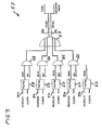
- FIG. 1 shows a schematic of a block diagram of a beam delivery device 21, according to an embodiment of the invention.
- the beam allocation device 21 forms an arbitration unit 26 with three switching blocks, namely a switching logic 27, a monitoring unit 28, and a sequencer 29.
- the control rooms 8-12 of different request entities are electrically connected to the switching logic 27 via bus lines 51 and special lines 34-38.
- the different request entities are in this embodiment of the invention three treatment rooms, which are identified in Figure 2 by the reference numerals 13-15, of which the treatment room 15 belongs to a gantry, with which the angle of incidence in the patient for the ion beam can be changed by 360 ° ,
- Another control room 11 is provided for quality assurance QS in a quality assurance room 16 shown in FIG. 2, and a fifth control room 12 is assigned to the accelerator.
- the switching logic 27 of the arbitration unit 26 has access to the spill abort system 31 of the acceleration area via signal lines 30.
- the spill abort system 31 of the acceleration region has two components, viz an exciter 33 and the spill abort magnet 32 to which each of the signal lines 34, 35, 37 and 38 lead.
- the monitoring unit 28 of the arbitration unit 26 has an input signal connection 40 from the scheduler 29 of the arbitration unit 26 and via input signal connections 41 in the form of a signal bus from the switching logic 27 of the arbitration unit 26. Further, the monitoring unit 28 of the arbitration unit 26 has four output signal connections 42-45 Sequencer 29 of the arbitration unit 26 communicates with the monitoring unit 28 via the input signal connection 40 of the monitoring unit 28 and is connected to the switching logic 27 of the arbitration unit 26 via a bus 52 and an output signal line 54.
- the arbitration unit 26 of this beam allocation device 21 is connected to a scheduler 46, which is connected to the switching logic 27 via a bus line 53, and via an output signal line 55 to the flow control 29 of the arbitration unit 26 can intervene.
- These signal lines 53 and 55 and also the scheduler 46 itself are not security relevant, so that the arbitration unit 26 in the absence of a scheduler 46, or in the event of failure of a scheduler 46 the control rooms 8-12 in turn gives opportunity with the arbitration unit 26 and the switching logic 27th the arbitration unit 26 via the signal buses 51 and the special lines 34-38.
- each control room has immediate access to the spill abort system via the redundant signal paths 39 and 49 31, wherein the redundant signal path 49 provides access to the spill abort magnet 32 and the redundant signal drop path 39 provides access to the exciter 33 for the control rooms 8-12.
- the redundant signal path 49 provides access to the spill abort magnet 32
- the redundant signal drop path 39 provides access to the exciter 33 for the control rooms 8-12.
- access switching elements in the control rooms 8-12 are connected in series to the redundant signal paths 39 and 49, so that upon triggering an interruption of the access switching elements through one of the control rooms 8 to 12 the rest of the control rooms can no longer access the Spillabbruchsystem 31.
- the spill abort system 31 uses a total of 4 elements in this irradiation technique, but only two elements, namely the exciter 33 and the spill abort magnet 32, are shown in the block diagram. Two of these elements (two deflecting magnets per irradiation station) do not belong to the acceleration range, but are deflection components 4 to 7, as shown in FIG. 2, which deflect the beam from a transport path in the direction of the respective requesting irradiation space. They are therefore confirmed directly from the respective control room 8 to 12 of an irradiation room. For this purpose, they are controlled directly from the respective control room 8 to 10 of an irradiation room for a demolition, with which an irradiation is to be carried out.
- the other two elements shown in the block diagram with the exciter 33 and the spill-stop magnet 32 are located in the area of the beam guide which is common to all the irradiation stations and are therefore alternately subjected to the control of the different irradiation spaces.
- the control is switched over by the arbitration unit 26 according to the invention, wherein the Allocation of the spill abort system 31, as shown in the block diagram of Figure 1, is highly security-relevant in the sense of the radiation protection law for medical facilities.
- the arrangement and distribution of the signal lines 34-38 are explicitly designated, wherein the reference numeral 34 is a request line, the reference numeral 35 a grant line, the reference numeral 36 a clear line, the reference numeral 37 an interlock line and the reference numeral 38 a Spillpause effet mark.
- the scheduler 46 of the block diagram of Figure 1 does not belong to the highly security relevant components of the beam allocation device 21, however, it has a close connection from a logical point of view, to the arbitration unit 26.
- the scheduled sequence of the irradiations is determined by a queue coming from a central computer the irradiation technique, the so-called Scheduling computer managed.
- the associated scheduling application is accessible from all 4 local control rooms 8 to 11, the accelerator control room 12 and various other computers of a hospital network.
- the planned sequence of irradiations is constantly changing over the course of a day.
- the scheduling application checks the existing sequence with each change by the user and after each irradiation, changes it if necessary and corrects accordingly the estimates for the planned start of irradiation of a field. These changes usually only move in the range of a few minutes one day. Under these conditions, the scheduler 46 of the arbitration unit 26 via its output signal line 55 a default to the scheduler 29 of the arbitration unit 26 for each next allocation of the beam sovereignty.
- the user request of the allocation of the beam is made from the respective control room 8-12. This request is acknowledged by the arbitration unit 26.
- the spill abort system 31 must then be reserved for this irradiation space of the control room, for example the control room 8.
- the allocation of the beam must be reset from the respective control room 8-12. Without acknowledged allocation rights, the irradiation will not start. During the irradiation, the access rights can not and must not be returned. After completion of the irradiation, however, the access rights must again be actively returned from the control room 8 to the arbitration unit 26.
- a scheduling application is not available, then the operation is still maintained via the arbitration unit 26. If a scheduling application is available, the allocation rights are assigned according to this application. However, if this is not possible, the allocation is made according to the method in which the arbitration unit 26 gives the control rooms 8-12 in turn the opportunity to reserve access rights. In addition, the accelerator control system or the accelerator control room 12 is notified of the granted access right of an irradiation facility. For security reasons, the request instances and their control rooms 8-12 do not receive access rights when the arbitration unit 26 is off or inoperative. That means the entire system is up. This action is required because the arbitration unit 26 manages the spill abort system 31 of the acceleration area. Without access to this fast abort system, neither irradiation is permitted nor possible on account of the arbitration unit 26 according to the invention. With the arbitration unit 26 In addition, a test option for the function verification is provided.
- the accelerator with the control room 12 can also be assigned control of the spill abort system 31 by the arbitration unit 26, in the following the control rooms 8 to 12 are also called request entities.
- the control of the accelerator includes all parts of the beam guidance that have been explicitly released for the accelerator and all irradiation places that are under the control of the accelerator control system.
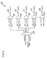
- FIG. 2 shows a schematic diagram of a particle accelerator 1 with components which are used by the beam allocation device 21 according to FIG.
- the particle accelerator 1 has an acceleration region 2 in the form of a synchrotron, which accelerates ion packets to energies of approximately 4500 MeV. These ion packets are generated in an ion source 89 and pre-accelerated via a linear accelerator 56, as well as coupled into the accelerator ring 2 in a coupling-in region 47 in which the exciter 33 is also arranged.
- the exciter 33 is a high-frequency resonance component in this coupling-in region 47 of the accelerator 2 and can trigger a beam break in microseconds by adjusting the resonance tuning.
- the spill abort magnet 32 which is the same as the exciter 33 for rapid beam termination during ion beam treatment in the raster scan method security relevant used arranged.
- deflection magnets 18 to 20 are arranged for each irradiation room, which deflect the ion beam 17 to the irradiation rooms 13-15.
- the irradiation rooms 13-15 are the Assigned control rooms 8-10, which can act directly on the deflection 18-20, and can cause a beam break to the collection chambers 22-25 in a few hundred milliseconds. These deflecting components 4-7 of the transport path 3 are thus not as fast as the beam abortment possibilities by the spill abort components 32 and 33 in the irradiation ring 2.
- FIGS. 3 shows a schematic diagram of a request circuit 57 for processing request signals REQPULS1-REQPULS5 via request lines 34 from the control rooms 8-12 shown in FIGS. 1 and 2.
- the request circuit 57 ensures that in each case only the request signal of the requesting entity or the active control room that is currently active from the point of view of the execution control of the arbitration unit is forwarded to the exciter 33 or spill abort magnet 32 shown in FIGS. 1 and 2.
- the request signals REQPULS1 to REQPULS5 are applied to flip-flops 58 to 62 of the arbitration unit's switching logic, with the flip-flops 58-62 previously being reset to neutral via the inputs CLEAR1-CLEAR5.
- the outputs of the flip-flops 58-61 are supplied to logical ANDGATEs 63-66, while only the request requests are forwarded via second inputs BZ1 to BZ4 of the ANDGATEs 63-66, which have a confirmed, active beam target BZ with the second input.
- the outputs of the ANDGATEs 63-66 are supplied to an ORGATE 67, the outputs REQEX and REQBU each via a request line 34 to the exciter or the Spillabbruchmagneten the Spillabbruchsystems the accelerator ring are connected.
- FIG. 4 shows a schematic diagram of a Grantscaria 68, which are now passed from Grant effet GRANTEX and GRANTBU from the Exciter or the Spillabbruchmagneten the Spillabbruchsystems via an ANDGATE 69 to corresponding ANDGATEs 70-73, which have next to this input from the ANDGATE 69 two further inputs BZ1 to BZ4 and REQ1 to REQ4, which ensure that both a request signal on one of the inputs REQ1 to REQ4, and a signal for a confirmed, active beam target is applied to one of the inputs BZ1 to BZ4 of the four ANDGATEs 70-73.
- the grant signal GRANT1 to GRANT5 requires a request at the inputs REQ1 to REQ5 of the ANDGATEs 70-74 and arbitration by the arbitration unit at the inputs BZ1 to BZ5 of the ANDGATEs 70-74.
- the checking of the request signal is redundant at this point, since the allocation by the Arbitr michssvik requires a request of the request instance or the control rooms.
- the accelerator does not require a grant signal from the spill abort element, but only the arbitration unit's allocation, which however is also signaled via the grant line GRANT5. It is thus ensured safety-relevant by this Grantscaria that only one request entity or a control room is given by the Arbitr michsstechnik with a grant signal on the Grant effet 35 to one of the control rooms.
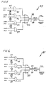
- FIG. 5 shows a schematic diagram of a spill pause circuit 75.
- This spill pause circuit 75 with the spill pause lines 38 can only be used by all four control rooms of the three treatment rooms and the one quality assurance room if there is a grant signal GRANT1 to GRANT4 of the spill abort elements of the spill abort system.
- the spill pause circuit 75 comprises four ANDGATEs 76-79, each having two inputs for a grant signal GRANT1 to GRANT4 and a spill signal SPILL1 to SPILL4, these signals being applied to the ANDGATEs 76-79 via grant lines 35 and spill pause lines 38.
- the outputs of the ANDGATEs 76-79 lead to inputs of an ORGATE 80, which has two outputs SPILLEX and SPILLBU, which are connected to the exciter or the spill abort magnet via a respective Spillpaus effet 38.
- the accelerator has the sovereignty, it will directly control the exciter and the spill stop magnet.
- the Spillpause line 38 is therefore not used by the accelerator.
- the Spillpause circuit 75 is not distinguished whether a Spillpause or already present a Spillende. The decision as to whether the residual beam in the acceleration area, the synchrotron, should be destroyed, is met solely by the accelerator control system in the corresponding control room.
- FIG. 6 shows a schematic diagram of an interlock circuit 85 for processing interlock signals INTL1 to INTL4 via interlock lines 37 through ANDGATEs 81-84 at the inputs of which a grant signal GRANT1 to GRANT4 must simultaneously be applied via the grant lines 35 in order to pass through one of the outputs of the ANDGATEs 81-84. 84 to the input of an ORGATE 86.
- the ORGATE 86 in turn has two outputs INTLEX and INTLBU, which lead to the exciter and the spill abort magnet via Interlock effet 37.
- the interlock line 37 of the exciter and the spill abort magnet from all four irradiation sites can only be used when the grantsignal GRANT1 to GRANT4 of the spill abort elements. If the accelerator is high enough, it directly controls the exciter and the spill abort magnet so that the interlock line 37 is not used by the accelerator.
- FIG. 7 shows a schematic of a flow diagram 95 of a flow control of an arbitration unit.
- a scheduler may or may not be present. Accordingly, the flow through the flowchart 95 changes.
- the beam destination of the scheduler is defined by the reference SZ
- the requesting beam destination and the requesting control space, respectively are indicated by AZ
- a confirmed, active beam target is indicated by the reference BZ.
- This sequence control receives the arbitration unit from the scheduler via a digital on / off module, the desired next request instance or the next requesting control room.
- the request instances which are identified in flowchart 95 as AZ1 to AZ4, correspond to the irradiation spaces H1, H2, gantry and QS in the block diagram shown in FIG.
- the request instance AZ5 corresponds to the accelerator to which the beam guidance up to the beam destroyer of the accelerator and all irradiation places released for the accelerator belongs.
- the request instance SZ6 means that there is no allocation of sovereignty at the moment, and the request instance SZ7 means that the scheduler is not active and does not supply any defaults, so that the arbitration unit independently awards the sovereignty. This allocation by the arbitration unit should then be carried out according to an all-round procedure, in which the arbitration unit the request units or control rooms in turn allows the opportunity to make a reservation.
- the connection between the scheduler and the arbitration unit is secured by suitable reserved direct lines or via other mechanisms insofar as the arbitration unit recognizes when the scheduler is not active, and thus the read request instances are invalid in any case.
- the procedure is as if the requesting instance 7 had been read, which corresponds to a request to proceed according to a series procedure.
- the absence of the scheduler signals is visually displayed on the arbitration unit and also the status of all request, grant and interlock lines and the selected request instance is made visually visible in a running scheduler.
- the arbitration units have a local mode in which, in principle, no attempt is made to read a request instance or a control room from the scheduler so that a local switch also effects an allocation in the series procedure. The state of the local switch in the respective control room is also visually displayed on the device.
- Flowchart 95 complements the processing of request, grant, and interlock signals described above.
- the flow control of the arbitration unit reads in accordance with the flowchart 95 the desired by the scheduler request authority or the corresponding control room, which is also referred to as a scheduler instance SI, a.
- the irradiation entity BI is forwarded to the request and grant circuits and ensures in this way that only the selected location reserves the spill abort elements can.
- the flow control of the arbitration unit no longer has any influence. In particular, the interlock signal is not affected by the flow control.
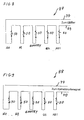
- FIG. 8 shows a schematic diagram of the series connection 87 of potential-free contacts 50 of the control rooms for a spill abortion via an exciter of the acceleration area.
- the exciter Via a redundant signal path 39, the exciter is driven directly from one of the control rooms, in order to bring about a jet break within a few microseconds.
- the redundant signal path 39 are breaker contacts 50 for the three control rooms with irradiation rooms H1, H2 and GANTRY, as well as for the quality assurance room QS and for the arbitration unit ABT, which can also provide the exciter for a rapid beam termination via the redundant signal path 39.
- FIG. 9 shows a schematic diagram of the series circuit 88 of potential-free contacts 50 of the control rooms for a spill abortion via a spill abort magnet of the acceleration area.
- the potential-free contacts 50 of the spill abortion system are thus present twice per excitation space and control space for the exciter and the spill abort magnet. They can only cause the spill abort if irradiation was started at the corresponding irradiation site, but not if no irradiation activities take place in the irradiation room.
- the individual potential-free contacts 50 of the irradiation sites are connected in series and are independent of the arbitration mechanism itself.
- the arbitration unit has the possibility to trigger in this way via a spill abort on the redundant signal paths 39 or 49.
Landscapes
- Health & Medical Sciences (AREA)
- Engineering & Computer Science (AREA)
- Biomedical Technology (AREA)
- Pathology (AREA)
- Nuclear Medicine, Radiotherapy & Molecular Imaging (AREA)
- Radiology & Medical Imaging (AREA)
- Life Sciences & Earth Sciences (AREA)
- Animal Behavior & Ethology (AREA)
- General Health & Medical Sciences (AREA)
- Public Health (AREA)
- Veterinary Medicine (AREA)
- Radiation-Therapy Devices (AREA)
- Particle Accelerators (AREA)
Applications Claiming Priority (3)
| Application Number | Priority Date | Filing Date | Title |
|---|---|---|---|
| DE102004025263 | 2004-05-19 | ||
| DE102004027071A DE102004027071A1 (de) | 2004-05-19 | 2004-06-02 | Strahlzuteilungsvorrichtung und Strahlzuteilungsverfahren für medizinische Teilchenbeschleuniger |
| EP05010450A EP1598094B1 (fr) | 2004-05-19 | 2005-05-13 | Méthode d'allocation de faisceau pour accélérateurs médicaux de particules |
Related Parent Applications (2)
| Application Number | Title | Priority Date | Filing Date |
|---|---|---|---|
| EP05010450.4 Division | 2005-05-13 | ||
| EP05010450A Division EP1598094B1 (fr) | 2004-05-19 | 2005-05-13 | Méthode d'allocation de faisceau pour accélérateurs médicaux de particules |
Publications (3)
| Publication Number | Publication Date |
|---|---|
| EP1785162A2 true EP1785162A2 (fr) | 2007-05-16 |
| EP1785162A3 EP1785162A3 (fr) | 2007-07-18 |
| EP1785162B1 EP1785162B1 (fr) | 2011-02-23 |
Family
ID=34936492
Family Applications (2)
| Application Number | Title | Priority Date | Filing Date |
|---|---|---|---|
| EP07004468A Expired - Lifetime EP1785162B1 (fr) | 2004-05-19 | 2005-05-13 | Installation d'irradiation médicale comportant un accélérateur de particules |
| EP05010450A Expired - Lifetime EP1598094B1 (fr) | 2004-05-19 | 2005-05-13 | Méthode d'allocation de faisceau pour accélérateurs médicaux de particules |
Family Applications After (1)
| Application Number | Title | Priority Date | Filing Date |
|---|---|---|---|
| EP05010450A Expired - Lifetime EP1598094B1 (fr) | 2004-05-19 | 2005-05-13 | Méthode d'allocation de faisceau pour accélérateurs médicaux de particules |
Country Status (5)
| Country | Link |
|---|---|
| US (2) | US7351988B2 (fr) |
| EP (2) | EP1785162B1 (fr) |
| JP (1) | JP2005353587A (fr) |
| AT (2) | ATE355871T1 (fr) |
| DE (3) | DE102004027071A1 (fr) |
Families Citing this family (129)
| Publication number | Priority date | Publication date | Assignee | Title |
|---|---|---|---|---|
| JP3859605B2 (ja) * | 2003-03-07 | 2006-12-20 | 株式会社日立製作所 | 粒子線治療システム及び粒子線出射方法 |
| DE102004027071A1 (de) * | 2004-05-19 | 2006-01-05 | Gesellschaft für Schwerionenforschung mbH | Strahlzuteilungsvorrichtung und Strahlzuteilungsverfahren für medizinische Teilchenbeschleuniger |
| EP3557956A1 (fr) | 2004-07-21 | 2019-10-23 | Mevion Medical Systems, Inc. | Générateur de forme d'onde de fréquence radio programmable pour un synchrocyclotron |
| JP4489529B2 (ja) * | 2004-07-28 | 2010-06-23 | 株式会社日立製作所 | 粒子線治療システム及び粒子線治療システムの制御システム |
| DE102005044409B4 (de) | 2005-09-16 | 2007-11-29 | Siemens Ag | Partikeltherapieanlage und Verfahren zur Ausbildung eines Strahlpfads für einen Bestrahlungsvorgang in einer Partikeltherapieanlage |
| DE102005044408B4 (de) * | 2005-09-16 | 2008-03-27 | Siemens Ag | Partikeltherapieanlage, Verfahren und Vorrichtung zur Anforderung eines Partikelstrahls |
| ES2730108T3 (es) | 2005-11-18 | 2019-11-08 | Mevion Medical Systems Inc | Radioterapia de partículas cargadas |
| US8581523B2 (en) | 2007-11-30 | 2013-11-12 | Mevion Medical Systems, Inc. | Interrupted particle source |
| US8933650B2 (en) | 2007-11-30 | 2015-01-13 | Mevion Medical Systems, Inc. | Matching a resonant frequency of a resonant cavity to a frequency of an input voltage |
| JP5074915B2 (ja) * | 2007-12-21 | 2012-11-14 | 株式会社日立製作所 | 荷電粒子ビーム照射システム |
| US9910166B2 (en) | 2008-05-22 | 2018-03-06 | Stephen L. Spotts | Redundant charged particle state determination apparatus and method of use thereof |
| US8373146B2 (en) * | 2008-05-22 | 2013-02-12 | Vladimir Balakin | RF accelerator method and apparatus used in conjunction with a charged particle cancer therapy system |
| US8399866B2 (en) | 2008-05-22 | 2013-03-19 | Vladimir Balakin | Charged particle extraction apparatus and method of use thereof |
| WO2009142545A2 (fr) | 2008-05-22 | 2009-11-26 | Vladimir Yegorovich Balakin | Procédé et appareil de positionnement d'un patient en vue du traitement d'un cancer par particules chargées |
| US8642978B2 (en) * | 2008-05-22 | 2014-02-04 | Vladimir Balakin | Charged particle cancer therapy dose distribution method and apparatus |
| US7940894B2 (en) * | 2008-05-22 | 2011-05-10 | Vladimir Balakin | Elongated lifetime X-ray method and apparatus used in conjunction with a charged particle cancer therapy system |
| US8975600B2 (en) | 2008-05-22 | 2015-03-10 | Vladimir Balakin | Treatment delivery control system and method of operation thereof |
| US9616252B2 (en) | 2008-05-22 | 2017-04-11 | Vladimir Balakin | Multi-field cancer therapy apparatus and method of use thereof |
| US10092776B2 (en) | 2008-05-22 | 2018-10-09 | Susan L. Michaud | Integrated translation/rotation charged particle imaging/treatment apparatus and method of use thereof |
| US9095040B2 (en) | 2008-05-22 | 2015-07-28 | Vladimir Balakin | Charged particle beam acceleration and extraction method and apparatus used in conjunction with a charged particle cancer therapy system |
| US8766217B2 (en) * | 2008-05-22 | 2014-07-01 | Vladimir Yegorovich Balakin | Multi-field charged particle cancer therapy method and apparatus |
| US9177751B2 (en) | 2008-05-22 | 2015-11-03 | Vladimir Balakin | Carbon ion beam injector apparatus and method of use thereof |
| US8129699B2 (en) * | 2008-05-22 | 2012-03-06 | Vladimir Balakin | Multi-field charged particle cancer therapy method and apparatus coordinated with patient respiration |
| WO2009142548A2 (fr) * | 2008-05-22 | 2009-11-26 | Vladimir Yegorovich Balakin | Procédé et dispositif de radiographie utilisés conjointement avec un système de traitement anticancéreux par particules chargées |
| US9737734B2 (en) | 2008-05-22 | 2017-08-22 | Susan L. Michaud | Charged particle translation slide control apparatus and method of use thereof |
| US8624528B2 (en) * | 2008-05-22 | 2014-01-07 | Vladimir Balakin | Method and apparatus coordinating synchrotron acceleration periods with patient respiration periods |
| US10143854B2 (en) | 2008-05-22 | 2018-12-04 | Susan L. Michaud | Dual rotation charged particle imaging / treatment apparatus and method of use thereof |
| US8598543B2 (en) | 2008-05-22 | 2013-12-03 | Vladimir Balakin | Multi-axis/multi-field charged particle cancer therapy method and apparatus |
| EP2283713B1 (fr) * | 2008-05-22 | 2018-03-28 | Vladimir Yegorovich Balakin | Appareil de traitement du cancer par particules chargees a axes multiples |
| US8373143B2 (en) * | 2008-05-22 | 2013-02-12 | Vladimir Balakin | Patient immobilization and repositioning method and apparatus used in conjunction with charged particle cancer therapy |
| US9579525B2 (en) | 2008-05-22 | 2017-02-28 | Vladimir Balakin | Multi-axis charged particle cancer therapy method and apparatus |
| US8374314B2 (en) | 2008-05-22 | 2013-02-12 | Vladimir Balakin | Synchronized X-ray / breathing method and apparatus used in conjunction with a charged particle cancer therapy system |
| US8045679B2 (en) * | 2008-05-22 | 2011-10-25 | Vladimir Balakin | Charged particle cancer therapy X-ray method and apparatus |
| US9682254B2 (en) | 2008-05-22 | 2017-06-20 | Vladimir Balakin | Cancer surface searing apparatus and method of use thereof |
| US8841866B2 (en) | 2008-05-22 | 2014-09-23 | Vladimir Yegorovich Balakin | Charged particle beam extraction method and apparatus used in conjunction with a charged particle cancer therapy system |
| US9782140B2 (en) | 2008-05-22 | 2017-10-10 | Susan L. Michaud | Hybrid charged particle / X-ray-imaging / treatment apparatus and method of use thereof |
| US7943913B2 (en) | 2008-05-22 | 2011-05-17 | Vladimir Balakin | Negative ion source method and apparatus used in conjunction with a charged particle cancer therapy system |
| US8089054B2 (en) | 2008-05-22 | 2012-01-03 | Vladimir Balakin | Charged particle beam acceleration and extraction method and apparatus used in conjunction with a charged particle cancer therapy system |
| US8710462B2 (en) * | 2008-05-22 | 2014-04-29 | Vladimir Balakin | Charged particle cancer therapy beam path control method and apparatus |
| WO2009142547A2 (fr) * | 2008-05-22 | 2009-11-26 | Vladimir Yegorovich Balakin | Procédé et dispositif d'accélération d'un faisceau de particules chargées faisant partie d'un système de traitement anticancéreux par particules chargées |
| US8198607B2 (en) * | 2008-05-22 | 2012-06-12 | Vladimir Balakin | Tandem accelerator method and apparatus used in conjunction with a charged particle cancer therapy system |
| US8969834B2 (en) | 2008-05-22 | 2015-03-03 | Vladimir Balakin | Charged particle therapy patient constraint apparatus and method of use thereof |
| US7953205B2 (en) * | 2008-05-22 | 2011-05-31 | Vladimir Balakin | Synchronized X-ray / breathing method and apparatus used in conjunction with a charged particle cancer therapy system |
| US8368038B2 (en) | 2008-05-22 | 2013-02-05 | Vladimir Balakin | Method and apparatus for intensity control of a charged particle beam extracted from a synchrotron |
| US8436327B2 (en) * | 2008-05-22 | 2013-05-07 | Vladimir Balakin | Multi-field charged particle cancer therapy method and apparatus |
| US8637833B2 (en) | 2008-05-22 | 2014-01-28 | Vladimir Balakin | Synchrotron power supply apparatus and method of use thereof |
| CA2725493C (fr) * | 2008-05-22 | 2015-08-18 | Vladimir Yegorovich Balakin | Procede et appareil de reglage du trajet d'un faisceau de traitement du cancer par particules chargees |
| US8373145B2 (en) | 2008-05-22 | 2013-02-12 | Vladimir Balakin | Charged particle cancer therapy system magnet control method and apparatus |
| US9737272B2 (en) | 2008-05-22 | 2017-08-22 | W. Davis Lee | Charged particle cancer therapy beam state determination apparatus and method of use thereof |
| US9168392B1 (en) | 2008-05-22 | 2015-10-27 | Vladimir Balakin | Charged particle cancer therapy system X-ray apparatus and method of use thereof |
| US8519365B2 (en) * | 2008-05-22 | 2013-08-27 | Vladimir Balakin | Charged particle cancer therapy imaging method and apparatus |
| US20090314960A1 (en) * | 2008-05-22 | 2009-12-24 | Vladimir Balakin | Patient positioning method and apparatus used in conjunction with a charged particle cancer therapy system |
| US9744380B2 (en) | 2008-05-22 | 2017-08-29 | Susan L. Michaud | Patient specific beam control assembly of a cancer therapy apparatus and method of use thereof |
| US9937362B2 (en) | 2008-05-22 | 2018-04-10 | W. Davis Lee | Dynamic energy control of a charged particle imaging/treatment apparatus and method of use thereof |
| US10684380B2 (en) | 2008-05-22 | 2020-06-16 | W. Davis Lee | Multiple scintillation detector array imaging apparatus and method of use thereof |
| US8569717B2 (en) * | 2008-05-22 | 2013-10-29 | Vladimir Balakin | Intensity modulated three-dimensional radiation scanning method and apparatus |
| US8309941B2 (en) * | 2008-05-22 | 2012-11-13 | Vladimir Balakin | Charged particle cancer therapy and patient breath monitoring method and apparatus |
| US8896239B2 (en) * | 2008-05-22 | 2014-11-25 | Vladimir Yegorovich Balakin | Charged particle beam injection method and apparatus used in conjunction with a charged particle cancer therapy system |
| US8378311B2 (en) | 2008-05-22 | 2013-02-19 | Vladimir Balakin | Synchrotron power cycling apparatus and method of use thereof |
| US8093564B2 (en) * | 2008-05-22 | 2012-01-10 | Vladimir Balakin | Ion beam focusing lens method and apparatus used in conjunction with a charged particle cancer therapy system |
| US9155911B1 (en) | 2008-05-22 | 2015-10-13 | Vladimir Balakin | Ion source method and apparatus used in conjunction with a charged particle cancer therapy system |
| US9498649B2 (en) | 2008-05-22 | 2016-11-22 | Vladimir Balakin | Charged particle cancer therapy patient constraint apparatus and method of use thereof |
| US9737733B2 (en) | 2008-05-22 | 2017-08-22 | W. Davis Lee | Charged particle state determination apparatus and method of use thereof |
| US8144832B2 (en) * | 2008-05-22 | 2012-03-27 | Vladimir Balakin | X-ray tomography method and apparatus used in conjunction with a charged particle cancer therapy system |
| US10029122B2 (en) | 2008-05-22 | 2018-07-24 | Susan L. Michaud | Charged particle—patient motion control system apparatus and method of use thereof |
| US7939809B2 (en) * | 2008-05-22 | 2011-05-10 | Vladimir Balakin | Charged particle beam extraction method and apparatus used in conjunction with a charged particle cancer therapy system |
| US8188688B2 (en) | 2008-05-22 | 2012-05-29 | Vladimir Balakin | Magnetic field control method and apparatus used in conjunction with a charged particle cancer therapy system |
| US10548551B2 (en) | 2008-05-22 | 2020-02-04 | W. Davis Lee | Depth resolved scintillation detector array imaging apparatus and method of use thereof |
| US8378321B2 (en) * | 2008-05-22 | 2013-02-19 | Vladimir Balakin | Charged particle cancer therapy and patient positioning method and apparatus |
| US8129694B2 (en) * | 2008-05-22 | 2012-03-06 | Vladimir Balakin | Negative ion beam source vacuum method and apparatus used in conjunction with a charged particle cancer therapy system |
| US9981147B2 (en) | 2008-05-22 | 2018-05-29 | W. Davis Lee | Ion beam extraction apparatus and method of use thereof |
| US8907309B2 (en) | 2009-04-17 | 2014-12-09 | Stephen L. Spotts | Treatment delivery control system and method of operation thereof |
| US8718231B2 (en) | 2008-05-22 | 2014-05-06 | Vladimir Balakin | X-ray tomography method and apparatus used in conjunction with a charged particle cancer therapy system |
| US9855444B2 (en) | 2008-05-22 | 2018-01-02 | Scott Penfold | X-ray detector for proton transit detection apparatus and method of use thereof |
| US9044600B2 (en) | 2008-05-22 | 2015-06-02 | Vladimir Balakin | Proton tomography apparatus and method of operation therefor |
| US10070831B2 (en) | 2008-05-22 | 2018-09-11 | James P. Bennett | Integrated cancer therapy—imaging apparatus and method of use thereof |
| US9056199B2 (en) | 2008-05-22 | 2015-06-16 | Vladimir Balakin | Charged particle treatment, rapid patient positioning apparatus and method of use thereof |
| US8288742B2 (en) * | 2008-05-22 | 2012-10-16 | Vladimir Balakin | Charged particle cancer therapy patient positioning method and apparatus |
| US8178859B2 (en) | 2008-05-22 | 2012-05-15 | Vladimir Balakin | Proton beam positioning verification method and apparatus used in conjunction with a charged particle cancer therapy system |
| US9974978B2 (en) | 2008-05-22 | 2018-05-22 | W. Davis Lee | Scintillation array apparatus and method of use thereof |
| US8627822B2 (en) * | 2008-07-14 | 2014-01-14 | Vladimir Balakin | Semi-vertical positioning method and apparatus used in conjunction with a charged particle cancer therapy system |
| US8229072B2 (en) | 2008-07-14 | 2012-07-24 | Vladimir Balakin | Elongated lifetime X-ray method and apparatus used in conjunction with a charged particle cancer therapy system |
| US8625739B2 (en) | 2008-07-14 | 2014-01-07 | Vladimir Balakin | Charged particle cancer therapy x-ray method and apparatus |
| BRPI0924903B8 (pt) | 2009-03-04 | 2021-06-22 | Zakrytoe Aktsionernoe Obshchestvo Protom | aparelho para geração de um feixe de íons negativos para uso em uma terapia por radiação de partículas carregadas e método para geração de um feixe de íons negativos para uso com terapia por radiação de partículas carregadas |
| US10589128B2 (en) | 2010-04-16 | 2020-03-17 | Susan L. Michaud | Treatment beam path verification in a cancer therapy apparatus and method of use thereof |
| US9737731B2 (en) | 2010-04-16 | 2017-08-22 | Vladimir Balakin | Synchrotron energy control apparatus and method of use thereof |
| US10086214B2 (en) | 2010-04-16 | 2018-10-02 | Vladimir Balakin | Integrated tomography—cancer treatment apparatus and method of use thereof |
| US10188877B2 (en) | 2010-04-16 | 2019-01-29 | W. Davis Lee | Fiducial marker/cancer imaging and treatment apparatus and method of use thereof |
| US10625097B2 (en) | 2010-04-16 | 2020-04-21 | Jillian Reno | Semi-automated cancer therapy treatment apparatus and method of use thereof |
| US10556126B2 (en) | 2010-04-16 | 2020-02-11 | Mark R. Amato | Automated radiation treatment plan development apparatus and method of use thereof |
| US10179250B2 (en) | 2010-04-16 | 2019-01-15 | Nick Ruebel | Auto-updated and implemented radiation treatment plan apparatus and method of use thereof |
| US10555710B2 (en) | 2010-04-16 | 2020-02-11 | James P. Bennett | Simultaneous multi-axes imaging apparatus and method of use thereof |
| US10638988B2 (en) | 2010-04-16 | 2020-05-05 | Scott Penfold | Simultaneous/single patient position X-ray and proton imaging apparatus and method of use thereof |
| US10349906B2 (en) | 2010-04-16 | 2019-07-16 | James P. Bennett | Multiplexed proton tomography imaging apparatus and method of use thereof |
| US10751551B2 (en) | 2010-04-16 | 2020-08-25 | James P. Bennett | Integrated imaging-cancer treatment apparatus and method of use thereof |
| US10518109B2 (en) | 2010-04-16 | 2019-12-31 | Jillian Reno | Transformable charged particle beam path cancer therapy apparatus and method of use thereof |
| US11648420B2 (en) | 2010-04-16 | 2023-05-16 | Vladimir Balakin | Imaging assisted integrated tomography—cancer treatment apparatus and method of use thereof |
| US10376717B2 (en) | 2010-04-16 | 2019-08-13 | James P. Bennett | Intervening object compensating automated radiation treatment plan development apparatus and method of use thereof |
| CN102985136B (zh) | 2010-09-09 | 2015-07-01 | 三菱电机株式会社 | 粒子射线治疗装置 |
| US8700228B2 (en) * | 2011-03-29 | 2014-04-15 | Sumitomo Heavy Industries, Ltd. | Beam scheduler and beam allocation method of beam scheduler |
| US8963112B1 (en) | 2011-05-25 | 2015-02-24 | Vladimir Balakin | Charged particle cancer therapy patient positioning method and apparatus |
| EP2900326B1 (fr) | 2012-09-28 | 2019-05-01 | Mevion Medical Systems, Inc. | Commande de thérapie par particules |
| EP2901824B1 (fr) | 2012-09-28 | 2020-04-15 | Mevion Medical Systems, Inc. | Éléments d'homogénéisation de champ magnétique permettant d'ajuster la position de la bobine principale et procédé correspondant |
| CN104813747B (zh) | 2012-09-28 | 2018-02-02 | 梅维昂医疗系统股份有限公司 | 使用磁场颤振聚焦粒子束 |
| JP6121545B2 (ja) | 2012-09-28 | 2017-04-26 | メビオン・メディカル・システムズ・インコーポレーテッド | 粒子ビームのエネルギーの調整 |
| US10254739B2 (en) | 2012-09-28 | 2019-04-09 | Mevion Medical Systems, Inc. | Coil positioning system |
| TW201422279A (zh) | 2012-09-28 | 2014-06-16 | Mevion Medical Systems Inc | 聚焦粒子束 |
| EP2901823B1 (fr) | 2012-09-28 | 2021-12-08 | Mevion Medical Systems, Inc. | Contrôle de l'intensité d'un faisceau de particules |
| EP2901821B1 (fr) | 2012-09-28 | 2020-07-08 | Mevion Medical Systems, Inc. | Régénérateur de champ magnétique |
| TW201422278A (zh) | 2012-09-28 | 2014-06-16 | Mevion Medical Systems Inc | 粒子加速器之控制系統 |
| US8933651B2 (en) | 2012-11-16 | 2015-01-13 | Vladimir Balakin | Charged particle accelerator magnet apparatus and method of use thereof |
| US8791656B1 (en) | 2013-05-31 | 2014-07-29 | Mevion Medical Systems, Inc. | Active return system |
| US9730308B2 (en) | 2013-06-12 | 2017-08-08 | Mevion Medical Systems, Inc. | Particle accelerator that produces charged particles having variable energies |
| EP3049151B1 (fr) | 2013-09-27 | 2019-12-25 | Mevion Medical Systems, Inc. | Balayage par un faisceau de particules |
| WO2015075797A1 (fr) * | 2013-11-21 | 2015-05-28 | 三菱電機株式会社 | Dispositif de thérapie à particules |
| US10675487B2 (en) | 2013-12-20 | 2020-06-09 | Mevion Medical Systems, Inc. | Energy degrader enabling high-speed energy switching |
| US9962560B2 (en) | 2013-12-20 | 2018-05-08 | Mevion Medical Systems, Inc. | Collimator and energy degrader |
| US9661736B2 (en) | 2014-02-20 | 2017-05-23 | Mevion Medical Systems, Inc. | Scanning system for a particle therapy system |
| US9950194B2 (en) | 2014-09-09 | 2018-04-24 | Mevion Medical Systems, Inc. | Patient positioning system |
| KR101639369B1 (ko) * | 2014-10-22 | 2016-07-13 | 사회복지법인 삼성생명공익재단 | 방사선 치료기의 정도 관리 시스템 및 방법 |
| JP6427069B2 (ja) | 2015-05-27 | 2018-11-21 | 株式会社日立製作所 | 粒子線治療システム |
| US10786689B2 (en) | 2015-11-10 | 2020-09-29 | Mevion Medical Systems, Inc. | Adaptive aperture |
| US9907981B2 (en) | 2016-03-07 | 2018-03-06 | Susan L. Michaud | Charged particle translation slide control apparatus and method of use thereof |
| US10037863B2 (en) | 2016-05-27 | 2018-07-31 | Mark R. Amato | Continuous ion beam kinetic energy dissipater apparatus and method of use thereof |
| US10925147B2 (en) | 2016-07-08 | 2021-02-16 | Mevion Medical Systems, Inc. | Treatment planning |
| US11103730B2 (en) | 2017-02-23 | 2021-08-31 | Mevion Medical Systems, Inc. | Automated treatment in particle therapy |
| JP6940676B2 (ja) | 2017-06-30 | 2021-09-29 | メビオン・メディカル・システムズ・インコーポレーテッド | リニアモーターを使用して制御される構成可能コリメータ |
| EP3934751B1 (fr) | 2019-03-08 | 2024-07-17 | Mevion Medical Systems, Inc. | Collimateur et dégradeur d'énergie pour système de thérapie par particules |
| JP2024511277A (ja) | 2021-02-19 | 2024-03-13 | メビオン・メディカル・システムズ・インコーポレーテッド | 粒子線治療システムのためのガントリー |
Citations (2)
| Publication number | Priority date | Publication date | Assignee | Title |
|---|---|---|---|---|
| US5260581A (en) | 1992-03-04 | 1993-11-09 | Loma Linda University Medical Center | Method of treatment room selection verification in a radiation beam therapy system |
| US5895926A (en) | 1995-02-15 | 1999-04-20 | Loma Linda University Medical Center | Beamline control and security system for a radiation treatment facility |
Family Cites Families (22)
| Publication number | Priority date | Publication date | Assignee | Title |
|---|---|---|---|---|
| US4870287A (en) * | 1988-03-03 | 1989-09-26 | Loma Linda University Medical Center | Multi-station proton beam therapy system |
| JP2634513B2 (ja) * | 1991-09-11 | 1997-07-30 | 三菱電機株式会社 | 放射線治療装置 |
| JPH05190300A (ja) * | 1992-01-10 | 1993-07-30 | Toshiba Corp | 加速器システム |
| JPH076900A (ja) * | 1993-06-15 | 1995-01-10 | Hitachi Ltd | 高周波加速空胴及びイオンシンクロトロン加速器 |
| JP3518270B2 (ja) * | 1996-08-30 | 2004-04-12 | 株式会社日立製作所 | 荷電粒子ビーム装置 |
| JPH10247600A (ja) * | 1997-03-04 | 1998-09-14 | Toshiba Corp | 陽子加速器 |
| AU2103599A (en) * | 1998-01-14 | 1999-08-02 | Leonard Reiffel | System to stabilize an irradiated internal target |
| JPH10199700A (ja) * | 1998-02-27 | 1998-07-31 | Hitachi Ltd | 荷電粒子ビーム装置およびその運転方法 |
| JPH11329798A (ja) * | 1998-05-18 | 1999-11-30 | Toshiba Corp | 加速器のタイミング制御装置 |
| DE19835209A1 (de) * | 1998-08-04 | 2000-02-10 | Schwerionenforsch Gmbh | Vorrichtung und Verfahren zum Steuern einer Bestrahlungseinrichtung |
| EP0986070B1 (fr) * | 1998-09-11 | 2010-06-30 | GSI Helmholtzzentrum für Schwerionenforschung GmbH | Dispositif de thérapie par faisceau d'ions et procédé d'exploitation du dispositif |
| DE19907064A1 (de) * | 1999-02-19 | 2000-08-31 | Schwerionenforsch Gmbh | Verfahren zur Überprüfung einer Notabschaltung eines Ionenstrahl-Therapiesystems |
| DE19907138A1 (de) * | 1999-02-19 | 2000-08-31 | Schwerionenforsch Gmbh | Verfahren zur Überprüfung der Strahlerzeugungsmittel und der Strahlbeschleunigungsmittel eines Ionenstrahl-Therapiesystems |
| JP2000340400A (ja) * | 1999-05-26 | 2000-12-08 | Hitachi Ltd | 加速器装置 |
| JP2001085200A (ja) * | 1999-09-14 | 2001-03-30 | Hitachi Ltd | 加速器システム |
| JP2001307900A (ja) * | 2000-04-24 | 2001-11-02 | Hitachi Ltd | 加速器の運転監視装置 |
| DE10031074A1 (de) * | 2000-06-30 | 2002-01-31 | Schwerionenforsch Gmbh | Vorrichtung zur Bestrahlung eines Tumorgewebes |
| JP2003086400A (ja) * | 2001-09-11 | 2003-03-20 | Hitachi Ltd | 加速器システム及び医療用加速器施設 |
| JP3859605B2 (ja) * | 2003-03-07 | 2006-12-20 | 株式会社日立製作所 | 粒子線治療システム及び粒子線出射方法 |
| CN100509082C (zh) * | 2003-05-13 | 2009-07-08 | 离子束应用股份有限公司 | 在多室粒子束处理装置中自动粒子束指配的方法和系统 |
| JP4443917B2 (ja) * | 2003-12-26 | 2010-03-31 | 株式会社日立製作所 | 粒子線治療装置 |
| DE102004027071A1 (de) * | 2004-05-19 | 2006-01-05 | Gesellschaft für Schwerionenforschung mbH | Strahlzuteilungsvorrichtung und Strahlzuteilungsverfahren für medizinische Teilchenbeschleuniger |
-
2004
- 2004-06-02 DE DE102004027071A patent/DE102004027071A1/de not_active Withdrawn
-
2005
- 2005-05-13 AT AT05010450T patent/ATE355871T1/de not_active IP Right Cessation
- 2005-05-13 DE DE502005011004T patent/DE502005011004D1/de not_active Expired - Lifetime
- 2005-05-13 EP EP07004468A patent/EP1785162B1/fr not_active Expired - Lifetime
- 2005-05-13 AT AT07004468T patent/ATE499145T1/de active
- 2005-05-13 EP EP05010450A patent/EP1598094B1/fr not_active Expired - Lifetime
- 2005-05-13 DE DE502005000438T patent/DE502005000438D1/de not_active Expired - Lifetime
- 2005-05-18 US US11/131,978 patent/US7351988B2/en not_active Expired - Fee Related
- 2005-05-18 JP JP2005146061A patent/JP2005353587A/ja active Pending
-
2008
- 2008-03-31 US US12/059,494 patent/US20080258083A1/en not_active Abandoned
Patent Citations (2)
| Publication number | Priority date | Publication date | Assignee | Title |
|---|---|---|---|---|
| US5260581A (en) | 1992-03-04 | 1993-11-09 | Loma Linda University Medical Center | Method of treatment room selection verification in a radiation beam therapy system |
| US5895926A (en) | 1995-02-15 | 1999-04-20 | Loma Linda University Medical Center | Beamline control and security system for a radiation treatment facility |
Also Published As
| Publication number | Publication date |
|---|---|
| ATE499145T1 (de) | 2011-03-15 |
| EP1598094B1 (fr) | 2007-03-07 |
| US7351988B2 (en) | 2008-04-01 |
| EP1785162B1 (fr) | 2011-02-23 |
| DE502005000438D1 (de) | 2007-04-19 |
| US20080258083A1 (en) | 2008-10-23 |
| DE102004027071A1 (de) | 2006-01-05 |
| EP1598094A1 (fr) | 2005-11-23 |
| JP2005353587A (ja) | 2005-12-22 |
| ATE355871T1 (de) | 2007-03-15 |
| DE502005011004D1 (de) | 2011-04-07 |
| EP1785162A3 (fr) | 2007-07-18 |
| US20060113487A1 (en) | 2006-06-01 |
Similar Documents
| Publication | Publication Date | Title |
|---|---|---|
| EP1598094B1 (fr) | Méthode d'allocation de faisceau pour accélérateurs médicaux de particules | |
| EP1764133B1 (fr) | Système et procédé de thérapie par particules pour la formation d'une trajectoire d'un rayon pour un processus d'irradiation dans un système de thérapie par particules | |
| EP1764131B1 (fr) | Appareil et méthode de thérapie par particules pour l'allocation d'un faisceau de particules à un site d'irradiation | |
| DE602004007647T2 (de) | Verfahren und system zur automatischen strahlzuweisung in einer teilchenstrahlentherapieanlage mit mehreren räumen | |
| DE602005005744T2 (de) | Teilchenstrahl-Therapiesystem und Steuersystem für die Teilchenstrahltherapie | |
| DE602004010949T3 (de) | Einrichtung zur Bestrahlung mit Teilchenstrahlen und Bestrahlungsplanungseinheit | |
| EP1561491A1 (fr) | Procédé et dispositif pour adapter une grandeur de spot de faisceau ionique dans l'irradiation de tumeurs | |
| EP0978294B1 (fr) | Dispositif et procédé pour commander un appareil d'irradiation | |
| EP2453984B1 (fr) | Irradiation ou planification d'irradiation pour un procédé à balayage répété avec un faisceau de particules | |
| EP2506929B1 (fr) | Dispositif d'irradiation | |
| EP2830709B1 (fr) | Procédé et dispositif de détermination d'un plan de rayonnement pour une installation de rayonnement particulaire | |
| DE102007042337A1 (de) | Steuerungsvorrichtung und Verfahren zur Steuerung einer medizinische Diagnostik- und/oder Therapieanlage sowie medizinische Diagnostik- und/oder Therapieanlage | |
| EP2177244A1 (fr) | Installation de rayonnement de patients dotée de particules chargées et procédé de surveillance de l'installation | |
| WO2007054511A1 (fr) | Équipement de thérapie particulaire, protocole de thérapie et procédé de radiation pour un tel équipement de thérapie particulaire | |
| EP1764132A1 (fr) | Procédé et dispositif pour la configuration d'une trajectoire de faisceau d'un système de thérapie par faisceau de particules | |
| EP2039394A1 (fr) | Installation et procédé de fonctionnement d'une installation | |
| EP1909905A1 (fr) | Dispositif de rayonnement | |
| EP2247339B1 (fr) | Système de thérapie par un faisceau de protons | |
| EP2830710B1 (fr) | Procédé et dispositif de détermination d'un plan de rayonnement pour une installation de rayonnement particulaire | |
| DE102012210241B4 (de) | Verfahren und Vorrichtung zur Optimierung einer Bestrahlung mit einer Partikelbestrahlungsanlage mit mehreren Strahlauslässen | |
| EP4254281A1 (fr) | Procédé et agencement d'entretien des unités fonctionnelles dans une voie ferrée |
Legal Events
| Date | Code | Title | Description |
|---|---|---|---|
| PUAI | Public reference made under article 153(3) epc to a published international application that has entered the european phase |
Free format text: ORIGINAL CODE: 0009012 |
|
| 17P | Request for examination filed |
Effective date: 20070305 |
|
| AC | Divisional application: reference to earlier application |
Ref document number: 1598094 Country of ref document: EP Kind code of ref document: P |
|
| AK | Designated contracting states |
Kind code of ref document: A2 Designated state(s): AT BE BG CH CY CZ DE DK EE ES FI FR GB GR HU IE IS IT LI LT LU MC NL PL PT RO SE SI SK TR |
|
| PUAL | Search report despatched |
Free format text: ORIGINAL CODE: 0009013 |
|
| AK | Designated contracting states |
Kind code of ref document: A3 Designated state(s): AT BE BG CH CY CZ DE DK EE ES FI FR GB GR HU IE IS IT LI LT LU MC NL PL PT RO SE SI SK TR |
|
| 17Q | First examination report despatched |
Effective date: 20071011 |
|
| AKX | Designation fees paid |
Designated state(s): AT BE BG CH CY CZ DE DK EE ES FI FR GB GR HU IE IS IT LI LT LU MC NL PL PT RO SE SI SK TR |
|
| RAP1 | Party data changed (applicant data changed or rights of an application transferred) |
Owner name: GSI HELMHOLTZZENTRUM FUER SCHWERIONENFORSCHUNG GMB |
|
| GRAP | Despatch of communication of intention to grant a patent |
Free format text: ORIGINAL CODE: EPIDOSNIGR1 |
|
| RTI1 | Title (correction) |
Free format text: MEDICAL IRRADIATION SYSTEM HAVING A PARTICLE ACCELERATOR |
|
| GRAS | Grant fee paid |
Free format text: ORIGINAL CODE: EPIDOSNIGR3 |
|
| GRAA | (expected) grant |
Free format text: ORIGINAL CODE: 0009210 |
|
| AC | Divisional application: reference to earlier application |
Ref document number: 1598094 Country of ref document: EP Kind code of ref document: P |
|
| AK | Designated contracting states |
Kind code of ref document: B1 Designated state(s): AT BE BG CH CY CZ DE DK EE ES FI FR GB GR HU IE IS IT LI LT LU MC NL PL PT RO SE SI SK TR |
|
| REG | Reference to a national code |
Ref country code: GB Ref legal event code: FG4D Free format text: NOT ENGLISH |
|
| REG | Reference to a national code |
Ref country code: CH Ref legal event code: EP |
|
| REG | Reference to a national code |
Ref country code: IE Ref legal event code: FG4D Free format text: LANGUAGE OF EP DOCUMENT: GERMAN |
|
| REF | Corresponds to: |
Ref document number: 502005011004 Country of ref document: DE Date of ref document: 20110407 Kind code of ref document: P |
|
| REG | Reference to a national code |
Ref country code: DE Ref legal event code: R096 Ref document number: 502005011004 Country of ref document: DE Effective date: 20110407 |
|
| REG | Reference to a national code |
Ref country code: CH Ref legal event code: NV Representative=s name: BOVARD AG |
|
| REG | Reference to a national code |
Ref country code: SE Ref legal event code: TRGR |
|
| REG | Reference to a national code |
Ref country code: NL Ref legal event code: VDEP Effective date: 20110223 |
|
| LTIE | Lt: invalidation of european patent or patent extension |
Effective date: 20110223 |
|
| PG25 | Lapsed in a contracting state [announced via postgrant information from national office to epo] |
Ref country code: PT Free format text: LAPSE BECAUSE OF FAILURE TO SUBMIT A TRANSLATION OF THE DESCRIPTION OR TO PAY THE FEE WITHIN THE PRESCRIBED TIME-LIMIT Effective date: 20110623 Ref country code: ES Free format text: LAPSE BECAUSE OF FAILURE TO SUBMIT A TRANSLATION OF THE DESCRIPTION OR TO PAY THE FEE WITHIN THE PRESCRIBED TIME-LIMIT Effective date: 20110603 Ref country code: LT Free format text: LAPSE BECAUSE OF FAILURE TO SUBMIT A TRANSLATION OF THE DESCRIPTION OR TO PAY THE FEE WITHIN THE PRESCRIBED TIME-LIMIT Effective date: 20110223 Ref country code: GR Free format text: LAPSE BECAUSE OF FAILURE TO SUBMIT A TRANSLATION OF THE DESCRIPTION OR TO PAY THE FEE WITHIN THE PRESCRIBED TIME-LIMIT Effective date: 20110524 |
|
| PG25 | Lapsed in a contracting state [announced via postgrant information from national office to epo] |
Ref country code: BG Free format text: LAPSE BECAUSE OF FAILURE TO SUBMIT A TRANSLATION OF THE DESCRIPTION OR TO PAY THE FEE WITHIN THE PRESCRIBED TIME-LIMIT Effective date: 20110523 Ref country code: SI Free format text: LAPSE BECAUSE OF FAILURE TO SUBMIT A TRANSLATION OF THE DESCRIPTION OR TO PAY THE FEE WITHIN THE PRESCRIBED TIME-LIMIT Effective date: 20110223 Ref country code: NL Free format text: LAPSE BECAUSE OF FAILURE TO SUBMIT A TRANSLATION OF THE DESCRIPTION OR TO PAY THE FEE WITHIN THE PRESCRIBED TIME-LIMIT Effective date: 20110223 Ref country code: FI Free format text: LAPSE BECAUSE OF FAILURE TO SUBMIT A TRANSLATION OF THE DESCRIPTION OR TO PAY THE FEE WITHIN THE PRESCRIBED TIME-LIMIT Effective date: 20110223 Ref country code: CY Free format text: LAPSE BECAUSE OF FAILURE TO SUBMIT A TRANSLATION OF THE DESCRIPTION OR TO PAY THE FEE WITHIN THE PRESCRIBED TIME-LIMIT Effective date: 20110223 |
|
| REG | Reference to a national code |
Ref country code: IE Ref legal event code: FD4D |
|
| PG25 | Lapsed in a contracting state [announced via postgrant information from national office to epo] |
Ref country code: DK Free format text: LAPSE BECAUSE OF FAILURE TO SUBMIT A TRANSLATION OF THE DESCRIPTION OR TO PAY THE FEE WITHIN THE PRESCRIBED TIME-LIMIT Effective date: 20110223 Ref country code: IE Free format text: LAPSE BECAUSE OF FAILURE TO SUBMIT A TRANSLATION OF THE DESCRIPTION OR TO PAY THE FEE WITHIN THE PRESCRIBED TIME-LIMIT Effective date: 20110223 Ref country code: EE Free format text: LAPSE BECAUSE OF FAILURE TO SUBMIT A TRANSLATION OF THE DESCRIPTION OR TO PAY THE FEE WITHIN THE PRESCRIBED TIME-LIMIT Effective date: 20110223 |
|
| BERE | Be: lapsed |
Owner name: GSI HELMHOLTZZENTRUM FUR SCHWERIONENFORSCHUNG G.M. Effective date: 20110531 |
|
| PG25 | Lapsed in a contracting state [announced via postgrant information from national office to epo] |
Ref country code: SK Free format text: LAPSE BECAUSE OF FAILURE TO SUBMIT A TRANSLATION OF THE DESCRIPTION OR TO PAY THE FEE WITHIN THE PRESCRIBED TIME-LIMIT Effective date: 20110223 Ref country code: CZ Free format text: LAPSE BECAUSE OF FAILURE TO SUBMIT A TRANSLATION OF THE DESCRIPTION OR TO PAY THE FEE WITHIN THE PRESCRIBED TIME-LIMIT Effective date: 20110223 Ref country code: RO Free format text: LAPSE BECAUSE OF FAILURE TO SUBMIT A TRANSLATION OF THE DESCRIPTION OR TO PAY THE FEE WITHIN THE PRESCRIBED TIME-LIMIT Effective date: 20110223 |
|
| PG25 | Lapsed in a contracting state [announced via postgrant information from national office to epo] |
Ref country code: MC Free format text: LAPSE BECAUSE OF NON-PAYMENT OF DUE FEES Effective date: 20110531 |
|
| PLBE | No opposition filed within time limit |
Free format text: ORIGINAL CODE: 0009261 |
|
| STAA | Information on the status of an ep patent application or granted ep patent |
Free format text: STATUS: NO OPPOSITION FILED WITHIN TIME LIMIT |
|
| GBPC | Gb: european patent ceased through non-payment of renewal fee |
Effective date: 20110523 |
|
| 26N | No opposition filed |
Effective date: 20111124 |
|
| PG25 | Lapsed in a contracting state [announced via postgrant information from national office to epo] |
Ref country code: PL Free format text: LAPSE BECAUSE OF FAILURE TO SUBMIT A TRANSLATION OF THE DESCRIPTION OR TO PAY THE FEE WITHIN THE PRESCRIBED TIME-LIMIT Effective date: 20110223 |
|
| REG | Reference to a national code |
Ref country code: DE Ref legal event code: R097 Ref document number: 502005011004 Country of ref document: DE Effective date: 20111124 |
|
| PG25 | Lapsed in a contracting state [announced via postgrant information from national office to epo] |
Ref country code: BE Free format text: LAPSE BECAUSE OF NON-PAYMENT OF DUE FEES Effective date: 20110531 |
|
| PG25 | Lapsed in a contracting state [announced via postgrant information from national office to epo] |
Ref country code: GB Free format text: LAPSE BECAUSE OF NON-PAYMENT OF DUE FEES Effective date: 20110523 |
|
| PG25 | Lapsed in a contracting state [announced via postgrant information from national office to epo] |
Ref country code: LU Free format text: LAPSE BECAUSE OF NON-PAYMENT OF DUE FEES Effective date: 20110513 |
|
| PG25 | Lapsed in a contracting state [announced via postgrant information from national office to epo] |
Ref country code: IS Free format text: LAPSE BECAUSE OF FAILURE TO SUBMIT A TRANSLATION OF THE DESCRIPTION OR TO PAY THE FEE WITHIN THE PRESCRIBED TIME-LIMIT Effective date: 20110223 |
|
| PG25 | Lapsed in a contracting state [announced via postgrant information from national office to epo] |
Ref country code: TR Free format text: LAPSE BECAUSE OF FAILURE TO SUBMIT A TRANSLATION OF THE DESCRIPTION OR TO PAY THE FEE WITHIN THE PRESCRIBED TIME-LIMIT Effective date: 20110223 |
|
| PG25 | Lapsed in a contracting state [announced via postgrant information from national office to epo] |
Ref country code: HU Free format text: LAPSE BECAUSE OF FAILURE TO SUBMIT A TRANSLATION OF THE DESCRIPTION OR TO PAY THE FEE WITHIN THE PRESCRIBED TIME-LIMIT Effective date: 20110223 |
|
| REG | Reference to a national code |
Ref country code: DE Ref legal event code: R082 Ref document number: 502005011004 Country of ref document: DE |
|
| REG | Reference to a national code |
Ref country code: FR Ref legal event code: PLFP Year of fee payment: 12 |
|
| REG | Reference to a national code |
Ref country code: FR Ref legal event code: PLFP Year of fee payment: 13 |
|
| PGFP | Annual fee paid to national office [announced via postgrant information from national office to epo] |
Ref country code: FR Payment date: 20170522 Year of fee payment: 13 Ref country code: CH Payment date: 20170523 Year of fee payment: 13 |
|
| PGFP | Annual fee paid to national office [announced via postgrant information from national office to epo] |
Ref country code: AT Payment date: 20170519 Year of fee payment: 13 Ref country code: SE Payment date: 20170523 Year of fee payment: 13 Ref country code: IT Payment date: 20170524 Year of fee payment: 13 |
|
| REG | Reference to a national code |
Ref country code: CH Ref legal event code: PL |
|
| REG | Reference to a national code |
Ref country code: SE Ref legal event code: EUG |
|
| REG | Reference to a national code |
Ref country code: AT Ref legal event code: MM01 Ref document number: 499145 Country of ref document: AT Kind code of ref document: T Effective date: 20180513 |
|
| PG25 | Lapsed in a contracting state [announced via postgrant information from national office to epo] |
Ref country code: SE Free format text: LAPSE BECAUSE OF NON-PAYMENT OF DUE FEES Effective date: 20180514 Ref country code: AT Free format text: LAPSE BECAUSE OF NON-PAYMENT OF DUE FEES Effective date: 20180513 |
|
| PG25 | Lapsed in a contracting state [announced via postgrant information from national office to epo] |
Ref country code: CH Free format text: LAPSE BECAUSE OF NON-PAYMENT OF DUE FEES Effective date: 20180531 Ref country code: LI Free format text: LAPSE BECAUSE OF NON-PAYMENT OF DUE FEES Effective date: 20180531 |
|
| PG25 | Lapsed in a contracting state [announced via postgrant information from national office to epo] |
Ref country code: IT Free format text: LAPSE BECAUSE OF NON-PAYMENT OF DUE FEES Effective date: 20180513 Ref country code: FR Free format text: LAPSE BECAUSE OF NON-PAYMENT OF DUE FEES Effective date: 20180531 |
|
| PGFP | Annual fee paid to national office [announced via postgrant information from national office to epo] |
Ref country code: DE Payment date: 20200525 Year of fee payment: 16 |
|
| REG | Reference to a national code |
Ref country code: DE Ref legal event code: R119 Ref document number: 502005011004 Country of ref document: DE |
|
| PG25 | Lapsed in a contracting state [announced via postgrant information from national office to epo] |
Ref country code: DE Free format text: LAPSE BECAUSE OF NON-PAYMENT OF DUE FEES Effective date: 20211201 |