EP1785201A2 - Dispositif de protection contre la fumée - Google Patents
Dispositif de protection contre la fumée Download PDFInfo
- Publication number
- EP1785201A2 EP1785201A2 EP06021806A EP06021806A EP1785201A2 EP 1785201 A2 EP1785201 A2 EP 1785201A2 EP 06021806 A EP06021806 A EP 06021806A EP 06021806 A EP06021806 A EP 06021806A EP 1785201 A2 EP1785201 A2 EP 1785201A2
- Authority
- EP
- European Patent Office
- Prior art keywords
- exhaust
- exhaust air
- flap
- smoke
- fire
- Prior art date
- Legal status (The legal status is an assumption and is not a legal conclusion. Google has not performed a legal analysis and makes no representation as to the accuracy of the status listed.)
- Granted
Links
Images





Classifications
-
- B—PERFORMING OPERATIONS; TRANSPORTING
- B08—CLEANING
- B08B—CLEANING IN GENERAL; PREVENTION OF FOULING IN GENERAL
- B08B15/00—Preventing escape of dirt or fumes from the area where they are produced; Collecting or removing dirt or fumes from that area
-
- A—HUMAN NECESSITIES
- A62—LIFE-SAVING; FIRE-FIGHTING
- A62C—FIRE-FIGHTING
- A62C2/00—Fire prevention or containment
-
- G—PHYSICS
- G05—CONTROLLING; REGULATING
- G05D—SYSTEMS FOR CONTROLLING OR REGULATING NON-ELECTRIC VARIABLES
- G05D16/00—Control of fluid pressure
- G05D16/04—Control of fluid pressure without auxiliary power
-
- F—MECHANICAL ENGINEERING; LIGHTING; HEATING; WEAPONS; BLASTING
- F24—HEATING; RANGES; VENTILATING
- F24F—AIR-CONDITIONING; AIR-HUMIDIFICATION; VENTILATION; USE OF AIR CURRENTS FOR SCREENING
- F24F11/00—Control or safety arrangements
- F24F11/30—Control or safety arrangements for purposes related to the operation of the system, e.g. for safety or monitoring
- F24F11/32—Responding to malfunctions or emergencies
- F24F11/33—Responding to malfunctions or emergencies to fire, excessive heat or smoke
- F24F11/34—Responding to malfunctions or emergencies to fire, excessive heat or smoke by opening air passages
-
- F—MECHANICAL ENGINEERING; LIGHTING; HEATING; WEAPONS; BLASTING
- F24—HEATING; RANGES; VENTILATING
- F24F—AIR-CONDITIONING; AIR-HUMIDIFICATION; VENTILATION; USE OF AIR CURRENTS FOR SCREENING
- F24F11/00—Control or safety arrangements
- F24F11/30—Control or safety arrangements for purposes related to the operation of the system, e.g. for safety or monitoring
- F24F11/32—Responding to malfunctions or emergencies
- F24F11/33—Responding to malfunctions or emergencies to fire, excessive heat or smoke
- F24F11/35—Responding to malfunctions or emergencies to fire, excessive heat or smoke by closing air passages
Definitions
- building means in particular buildings with several floors, which are connected to one another via one or more staircases.
- staircases In such buildings in particular the staircases and possibly adjoining corridors escape routes or escape routes.
- Possible fire areas are adjacent units such as apartments, offices or the like.
- the smoke protection system is designed as a smoke protection differential pressure system, with a set by the overpressure system overpressure in the area of escape and rescue routes Smoke free in case of fire is guaranteed.
- the overpressure required for keeping smoke free must not exceed a permissible maximum value (eg 50 Pa).
- the supply air damper device provides for automatic air removal of excess air.
- control valves open automatically when the permissible overpressure under the effect of the scalar pressure forces and the excess air is transferred to the atmosphere with a flow-through pressure drop corresponding to the required permissible pressure of the pressure chamber, so that the control valve then automatically closes again.
- the possible fire areas in the individual floors can be connected via smoke control flaps to a common exhaust duct.
- the system is controlled, for example, by smoke detectors which are arranged in front of each access door in the corridor or the lock of the downstream rooms outside the protected area.
- the smoke protection pressure system namely the supply air system
- Each floor is a detector line.
- the outflow of smoke in the course of smoke extraction can take place via the exhaust air shaft (cf. DE 102 51 149 A1 ).
- a natural outflow over, for example, the facade of the building is provided.
- the problem in this context is that such natural outflows can be subject to significant meteorological influences. The randomness of these meteorological influences can disturb the safety function of such a differential pressure system. - This is where the invention starts.
- the invention is based on the object to provide a smoke protection system for a building of the type described above, which is simple Ensuring a reliable and safe function without meteorological influences can disturb the safety of the system.
- the invention teaches in a generic smoke protection system that at least one exhaust system is connected to the exhaust duct, which has at least one exhaust air system with negative pressure exhaust fan and at least one exhaust damper device, wherein the exhaust air -Regelklappenvorides has at least one spring-loaded control valve, which automatically opens when a predetermined limit negative pressure in the exhaust system and automatically closes when falling below the limit negative pressure.
- the exhaust air system can have at least one connected to the exhaust air duct exhaust box, to which the exhaust fan and the exhaust control valve device are connected, the control valves pivot in the course of opening in the direction of the interior of the exhaust box.
- Underpressure or limit negative pressure are defined in the context of the invention as positive pressure differences, that is, when lowering the pressure in a room, the negative pressure increases.
- the invention is initially based on the recognition that meteorological influences on the safety function of the system and in particular on the continuous and reliable removal of smoke can then be prevented if the smoke is not worked with a natural outflow, but with a machine Exhaust air system with the help of a fan actively the smoke is sucked out of the fire rooms over the exhaust air channel.
- the term fan includes in the context of the invention quite generally sucking and / or blowing conveyors and consequently also pumps or the like.
- the invention proposes to use an exhaust air damper device in the area of the exhaust air system in combination with an exhaust fan now ensures that at unacceptably low pressures in the field of fire chambers, the spring-loaded damper by the exhaust air system resulting negative pressure automatically opens.
- the excessively high pressure difference is thus avoided in the area of a closed door between the escape route and the firebox, so that only the positive permissible pressure difference through the supply air system can always be present above closed doors. If such a door now opens, the mechanical supply air system and the mechanical exhaust air system are in direct contact and in the area of the exhaust air system or in the area of the exhaust air box, the flap systems are automatically closed due to the valve opening pressure being undershot, so that a planned volume flow is transported out of the building through the supply and exhaust air system.
- the system of the invention ensures proper discharge of the smoke without disturbing meteorological influences and without the risk of unacceptably high differential pressures in the closed doors between escape routes and fire areas. This succeeds because it works with a mechanically extracting exhaust air system, in combination with a self-regulating differential pressure supply system and on the other hand, a self-regulating differential pressure-exhaust system, each using automatic control flap systems.
- the exhaust box according to the invention forms a collecting box.
- the exhaust air system has not only one, but preferably two or even more than two exhaust air damper devices.
- Each of the exhaust air damper devices may have one or more automatic control valves.
- the exhaust duct for example in the embodiment as L90 shaft, led out of the roof of the building and the exhaust box is therefore connected at the end in the region of the roof to the exhaust air duct.
- the flap opening pressure corresponding to the limit negative pressure of the control valve (s) of the exhaust air damper device corresponds approximately to the (maximum) duct pressure loss of the exhaust air duct at a given volume flow or ( slightly larger).
- the channel pressure loss is defined in the context of the invention as a positive pressure difference.
- the flap opening pressure, at which the control valves pivot inwards because of the low internal pressure in the collecting box, is here also defined as a positive pressure difference.
- the invention is based on the recognition that the discharge of a predetermined volume flow from the fire chambers via the exhaust air duct in the region of the exhaust air system is connected to a very specific pressure drop in the exhaust duct.
- the pressure in the exhaust box increases by the positive overpressure originally set in the escape route of, for example, 50 Pa, so that the negative pressure in the exhaust box drops and, consequently, the flap opening pressure falls below, so that the flaps automatically shut down.
- the planned volume flow is then conveyed via the exhaust air duct.
- both the supply air control flap devices and the exhaust air flap valve devices are of particular importance.
- conventional control valve devices with spring-loaded automatic control valves can be used in principle.
- damper devices according to claims 7 to 12 are used. Further details are the subject of the description of the figures.
- the subject matter of the invention is a method for evacuating smoke from fire compartments of a building and for keeping smoke out of escape routes of the building with a smoke protection system of the type described, wherein in the case of fire with the supply air system in the escape routes an overpressure is established, which a predetermined limit Overpressure does not exceed, with the exhaust air system smoke is discharged from a closed door from the escape route fire room such that in the fire room a predetermined minimum pressure is not exceeded, so that the pressure difference between the escape route and fire room on the closed door does not exceed the specified limit overpressure.
- Adherence to the permitted minimum pressure, for example atmospheric pressure, in the area of the fire compartment is achieved by automatically setting a predetermined limit vacuum in the exhaust system, for example in a collecting box, preferably taking into account the maximum possible pressure loss in the duct between the fire compartment and collecting tank.
- the building has a plurality of floors with several possible fire areas 18 and an escape route 19, wherein the fire rooms 18 are connected via doors T with the escape route 19.
- the escape route 19 is here in particular a stairwell.
- a supply air system 20 In the lower floor of a supply air system 20 is arranged, which has a supply air fan 21 which acts in the event of fire, the escape routes 19 and - at a possibly open door T - also a possible fire chamber 18 with pressure.
- the supply air system 20 has a supply air control valve device 22, which has at least one spring-loaded control valve 23, which automatically opens at a predetermined limit overpressure ⁇ P + to the outside and automatically closes when falling below the limit overpressure ⁇ P + .
- an exhaust duct 24 is provided, which is connected to the fire chambers 18 with the interposition of at least one smoke control flap 25 and is led out for discharging smoke from the building.
- an exhaust system 26 is connected, which has a exhaust air system 26 which acts on negative pressure exhaust air fan 27 and a plurality of exhaust air control valve devices 28.
- the exhaust air control valve devices 28 each have at least one spring-loaded control valve 29, which automatically opens at a predetermined limit negative pressure ⁇ P- in the exhaust system 26 and automatically closes when falling below the limit negative pressure ⁇ P-.
- the exhaust air system 26 has a connected to the exhaust duct 24 exhaust box 30, to which on the one hand the exhaust fan 27 and on the other hand, the two exhaust control valve devices 28 are connected, wherein the control valves 29 in the course of opening in the direction of the interior of the exhaust box 30 pivot.
- the two exhaust air control valve devices 28 are arranged on different sides of the exhaust box 30, namely on opposite sides.
- the exhaust air system 26 is shown schematically in FIG. 4. It is the Outgoing air duct 24 led out of the roof of the building and the exhaust box 30 is connected at the end in the region of the roof to the exhaust duct 24, for example, placed on the roof.
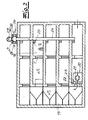
- Fig. 1 shows the building with the smoke protection system initially in the "normal state", that is without a fire in one of the floors.
- Supply air system 20 and exhaust system 26 are out of service.
- the pressure in the entire building corresponds essentially to the atmospheric pressure P0, that is, the pressure difference ⁇ P is about 0 Pa.
- the smoke control flaps 25 are closed.
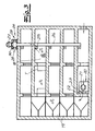
- both the supply air system 20 and the exhaust air system 26 are put into operation and the smoke compartment 25 assigned to the fire compartment 18 is opened.
- This functional state is indicated in FIG. 2.
- the supply air fan 21 now pumps air in the area of the escape route 19 (staircase). If a predetermined limit pressure ⁇ P + of, for example, 50 Pa is exceeded, then the control valves 23 of the supply air control device 22 automatically open, so that the desired overpressure ⁇ P + of, for example, 50 Pa automatically or automatically adjusts in the region of the escape route 19 , It can also be seen that the fire compartment 18 is separated from the overpressure escape route 19 by a closed door T.
- the exhaust air damper devices 28 are now dimensioned so that upon reaching or exceeding a predetermined limit negative pressure ⁇ P- in the collection box 30, the control valves 29 open automatically inward, so that no unacceptably high negative pressure in the area of the fire area can arise.
- the flap opening pressure essentially corresponds to the maximum channel pressure loss amount ⁇ P k or lies directly above this channel pressure loss amount.
- the channel pressure loss ⁇ P k is, for example 150 Pa, it is convenient to the flap opening pressure and consequently limit negative pressure ⁇ P - adjust the exhaust control valve device 28 to, for example, 160 Pa. Consequently, if a negative pressure of 160 Pa is reached in the region of the collecting tank 30, the control valves 29 open automatically.
- the resulting pressure loss in the collecting box 30 through the open flap surfaces is in the order of magnitude of the maximum duct pressure loss ⁇ P k , so that the open flap position of the connected suction-side channel 24 is no longer flowed through and therefore remains free of pressure loss.
- the supply air system 20 and the exhaust system 26 are in direct contact and in the collecting tank 30 the flap systems are automatically closed as a result of the valve opening pressure being undershot.
- the pressure in the collecting tank increases by the overpressure previously set in the escape route and consequently by, for example, 50 Pa, so that a negative pressure of only 110 Pa is now established so that the flaps close automatically. Now, the planned volume flow through the channel 24 is promoted.
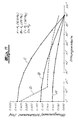
- the negative pressure ⁇ P in the region of the collecting tank 30 is plotted as a function of the delivered volume flow.
- the negative pressure is also defined here as a positive pressure difference, that is, when lowering the internal pressure in the collecting tank against the external pressure of the negative pressure increases.
- the characteristic KL of the vent fan 27 is located.
- the parabola b shows the course during the run-up of the fan 27 with the door closed.
- the negative pressure increases along the pressure loss parabola a until the flap opening pressure is reached, which here corresponds to the duct pressure loss ⁇ P k .
- FIGS. 6 to 11 The detailed structure of both the supply air control flap device 22 and the exhaust air damper devices 28 results from FIGS. 6 to 11.
- a control flap device for a smoke protection differential pressure system with a housing 1, at least one control flap 3 mounted pivotably in the housing about an axis of rotation 2 and at least one closing spring 5 connected on the one hand to the housing 1 and on the other hand via a connection part 4 to the control flap 3.
- the control flap 3 corresponds to either the control flap 23 of the supply air control flap device 22 or the control flap 29 of the exhaust control flap device 28.
- control flap device in the exemplary embodiment as a multi-valve device with a plurality of adjacently arranged control valves 3, 3 ', wherein the control valves 3, 3 'are connected to one another via a connecting linkage 6 and open and close together, and wherein a single common closing spring 5 acts on the plurality of control flaps 3, 3' with the interposition of a single common connecting part 4.
- the closing spring 5 is designed as a tension spring and in the embodiment as a cylindrical coil spring.
- the illustrated damper device can be used in the invention both as supply air damper device and as exhaust air damper device. In the following, this preferred embodiment will be described by way of example as a supply air damper device.
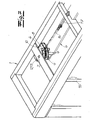
- control flap device illustrated in FIG. 6 separates a (rear) escape route in which an overpressure is to be generated and maintained by a (front) outer space A in which, for example, atmospheric pressure prevails.
- the control valves are not visible in FIGS. 6 and 7. They are arranged in the escape route facing (rear) portion of the housing 1 as shown in FIG. Fig. 8 shows a control valve 3 in the closed position.
- the closing spring 5 generates with its spring force F a closing moment M F holding the control flap 3 in the closed position or in the closed position.
- an overpressure is built in the (rear) escape route, which the escape route free of smoke.
- the control valve 3 pivots to form a flow opening by a predetermined opening angle ⁇ in the opening direction R as soon as an unilaterally acting on the control valve or control valves opening pressure or air pressure P generates a closing torque exceeding opening moment M L.
- the closing moment M F of the closing spring 5 is adjusted such that the opening moment M L exceeds the closing moment M F , in any case at an overpressure ⁇ P of 50 Pa, so that the control flap 3 opens and consequently the overpressure can be reduced by a predetermined amount , As soon as the overpressure has fallen so far that the closing moment again exceeds the opening moment, the control flap 3 automatically closes again.
- the opening direction R is indicated in the figures. With the control flap 3 open and close the other control valves 3 'simultaneously.
- the connecting part which connects the closing spring 5 with the control flap 3
- the connecting part is designed as a connecting lever 4 connected in an articulated manner to the control flap 3. Consequently, a separate connection joint component is provided in the context of the invention, which is connected on the one hand articulated to the closing spring 5 and on the other hand articulated to the control flap 3.
- the connection joint component 4 is consequently both pivotable with respect to the control flap and pivotable with respect to the closing spring.
- FIG. 8 shows that the connection lever 4 is not directly connected to the guide flap, but rather that the connection lever 4 is connected in an articulated manner to a connecting arm 7 connected in a rotationally fixed manner to the control flap 3. This connecting arm 7 is fixed at a fixed angle to the control flap 3.
- closing spring 5 on the one hand and control flap 3 (in the closed position) on the other hand are arranged substantially parallel to each other.
- the closing spring in the closed position at another angle, for example, perpendicular or approximately perpendicular to arrange the control flap.
- the connecting arm is rotatably connected to the control flap.
- the connecting lever 4 has at least one joint recess 12, in which a hinge pin 13 is rotatably mounted. The hinge pin 13 is connected to the control flap 3 or the connecting arm 7.
- the connecting lever 4 has a guide slot 8 and is thus formed as a curve with a curved elongated hole guide 9, wherein in this slot guide 9 is connected to the closing spring 5 end connected guide element in the form of a guide pin 10 hinged and slidably.
- the guide pin 10 is guided roller bearings in the slot guide 9. This is achieved, for example, by (shoulder) ball bearings mounted on both sides of the guide pin 10, which engage in the two elongated holes 9 '.
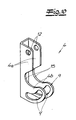
- the connection lever 4 is L-shaped in the side view and U-shaped in cross-section.
- the slot guide 9 with the two slots 9 ' is arranged. Due to the design of the connection lever 4 as a U-profile, it is expedient if in each case a joint recess 12 and a slot 9 'are provided in the two U-legs, which of course are aligned.
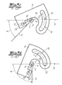
- the closing spring 5 is connected to the closing flap 3 via the connecting lever 4 such that the lever arm a acting on the flap 3 is greater than zero in all flap positions, so that the spring force produces a closing moment greater than zero in all flap positions.
- Lever a and length of the lever arm means in the invention, the vertical Distance of the spring force action line 14 or of the spring force vector from the pivot point or the axis of rotation 2.
- the spring force action line 14 and the control flap 3 and the connecting arm 7 connected thereto are merely indicated.
- the lever arm a is drawn in each case.
- the control flap pivots about the axis of rotation 2. Due to the articulated connection of the connection lever 4 on the one hand, the closing spring 5 and on the other hand the control valve 3, the control flap 3 pulls the connecting lever 4 initially in the direction of the axis of rotation 2, so that the connecting lever 4 comes into abutment against the rotary shaft 2 'at a predetermined critical angle (compare Fig. 9b).
- the lever arm a decreases sharply.
- Fig. 11 shows that the closing moment M F in a first angular range of a flap angle of 0 ° to a flap angle of about 15 ° drops sharply with a high slope and then in a second angle range to the fully open flap angle of 90 ° only slightly decreases with a slight slope. The waste in the second section is consequently (significantly) less than in the first section.
- the closing moment in the second section is constant at least in regions.
- the closing moment M F always has exactly two defined points of intersection with the opening moment M L at 25 Pa.
- the closing moment cuts both the curve B and the curve C defined at high flap opening angles and exactly once. Starting from the full open position at 90 °, the closing moment M F always increases continuously, so that a perfect flap return is ensured.
- the mechanical flap return system or the closing spring can consequently be designed with a substantially constant spring preload, which avoids the additional frictional effects due to increasing spring forces, thereby enabling reliable flap return.
- a guide surface 15 is arranged between the slot guide 9 and the joint recess 12, which is formed in the shape of a curve as it were formed and on which the joint 4 is guided in the course of opening on the rotary shaft 2 '.
- the L-shaped articulated guide lever 4 as it were concentrated around the axis 2, so that the described low moments of inertia occur.
- FIG. 6 shows that the housing 1 in the embodiment as a multi-flap device between the individual juxtaposed control valves 3, 3 'each having a partition wall 16 to form separate flow areas.
- the slot guide 9 extends in an approximately circular arc over an arc length of ⁇ 4 , up to ⁇ 2 , r, where r is the mean radius.
- the biased closing spring 5 is pivotally hinged to the housing 1 and that to a fixed to the housing 1 spring holder 17 which is adjustably or adjustably attached to the housing 1.
- adjustment options or adjustment options which allow to adapt the closing torque of the control valves and consequently also the flap opening pressure within certain limits to the required conditions. This can be useful in particular in the field of exhaust air damper device, since then on site for Example, the possibility exists to optimize the flap opening pressure taking into account the occurring channel pressure loss values.
Landscapes
- Physics & Mathematics (AREA)
- Automation & Control Theory (AREA)
- Fluid Mechanics (AREA)
- Engineering & Computer Science (AREA)
- General Physics & Mathematics (AREA)
- Health & Medical Sciences (AREA)
- Public Health (AREA)
- Business, Economics & Management (AREA)
- Emergency Management (AREA)
- Respiratory Apparatuses And Protective Means (AREA)
- Air-Flow Control Members (AREA)
- Absorbent Articles And Supports Therefor (AREA)
- Iron Core Of Rotating Electric Machines (AREA)
- Window Of Vehicle (AREA)
- Gas-Insulated Switchgears (AREA)
- Lock And Its Accessories (AREA)
Priority Applications (1)
| Application Number | Priority Date | Filing Date | Title |
|---|---|---|---|
| PL06021806T PL1785201T3 (pl) | 2005-11-10 | 2006-10-18 | Instalacja przeciwdymowa |
Applications Claiming Priority (1)
| Application Number | Priority Date | Filing Date | Title |
|---|---|---|---|
| DE102005053590A DE102005053590B4 (de) | 2005-11-10 | 2005-11-10 | Rauchschutzanlage sowie Verfahren zum Abführen von Rauch aus Brandräumen eines Gebäudes und zur Rauchfreihaltung von Fluchtwegen des Gebäudes |
Publications (3)
| Publication Number | Publication Date |
|---|---|
| EP1785201A2 true EP1785201A2 (fr) | 2007-05-16 |
| EP1785201A3 EP1785201A3 (fr) | 2008-06-11 |
| EP1785201B1 EP1785201B1 (fr) | 2010-12-01 |
Family
ID=37682595
Family Applications (1)
| Application Number | Title | Priority Date | Filing Date |
|---|---|---|---|
| EP06021806A Not-in-force EP1785201B1 (fr) | 2005-11-10 | 2006-10-18 | Dispositif de protection contre la fumée |
Country Status (5)
| Country | Link |
|---|---|
| EP (1) | EP1785201B1 (fr) |
| AT (1) | ATE490033T1 (fr) |
| DE (2) | DE102005053590B4 (fr) |
| ES (1) | ES2359453T3 (fr) |
| PL (1) | PL1785201T3 (fr) |
Cited By (7)
| Publication number | Priority date | Publication date | Assignee | Title |
|---|---|---|---|---|
| GB2472994A (en) * | 2009-08-25 | 2011-03-02 | Gilberts | Damper with a plurality of openings and blades |
| EP2500663A1 (fr) * | 2011-03-14 | 2012-09-19 | Jürgen Eidmann | Installation de protection contre la fumée |
| EP3078918A1 (fr) * | 2015-04-08 | 2016-10-12 | Gesellschaft für sicherheits- und brandschutz- | Installation de pression différentielle hybride de protection contre la fumée |
| EP3626899A1 (fr) * | 2018-09-20 | 2020-03-25 | Regli Bernhard | Bâtiment à plusieurs étages pourvu de moyens d'accès et de secours sécurisés en cas d'incendie |
| DE102018126010A1 (de) | 2018-10-19 | 2020-04-23 | Strulik Gmbh | Rauchschutzanlage |
| EP4303500A1 (fr) * | 2022-07-07 | 2024-01-10 | Technische Hochschule Mittelhessen | Dispositif d'introduction d'air amené |
| EP4656959A1 (fr) | 2024-05-27 | 2025-12-03 | Strulik GmbH | Installation de protection contre la fumée et procédé de protection contre la fumée d'un espace de sécurité |
Families Citing this family (3)
| Publication number | Priority date | Publication date | Assignee | Title |
|---|---|---|---|---|
| DE102011001261A1 (de) | 2011-03-14 | 2012-09-20 | Jürgen Eidmann | Rauchschutzdruckanlage und Verfahren zur Rauchfreihaltung eines Fluchtraumes |
| DE102015111678B4 (de) | 2015-07-17 | 2017-08-17 | Alfred Eichelberger Gmbh & Co. Kg | Rauchschutzdruckanlage für ein Gebäude und Verfahren zum Rauchfreihalten |
| IT201600074823A1 (it) * | 2016-07-18 | 2018-01-18 | Esseci S R L | Sistema di pressurizzazione di un ambiente in caso di incendio, e metodo per agevolare la chiusura di una porta tagliafuoco. |
Family Cites Families (7)
| Publication number | Priority date | Publication date | Assignee | Title |
|---|---|---|---|---|
| US3346007A (en) * | 1962-08-22 | 1967-10-10 | Israel State | Gas flow control louvres |
| GB2112282B (en) * | 1981-11-06 | 1985-07-31 | K G Smoke Dispersal Limited | Improvements in or relating to fire-safety systems |
| US4944216A (en) * | 1989-11-13 | 1990-07-31 | Mccutchen Wilmot R | Building emergency exhaust fan system |
| DE9409176U1 (de) * | 1994-06-07 | 1995-10-12 | Pafamax Brandschutztechnik GmbH, 34123 Kassel | Rauchschutzeinrichtung für einen geschlossenen Treppenraum |
| US5788571A (en) * | 1997-01-22 | 1998-08-04 | Ivison; John T. | Method of venting smoke from highrise residential buildings |
| DE19848736B4 (de) * | 1998-10-22 | 2004-11-11 | Horch, Fabian | Rauchschutzeinrichtung für Treppenräume oder dergleichen |
| DE50207222D1 (de) * | 2001-10-31 | 2006-07-27 | Alfred Eichelberger Gmbh & Co | Rauchschutz für räume |
-
2005
- 2005-11-10 DE DE102005053590A patent/DE102005053590B4/de not_active Expired - Fee Related
-
2006
- 2006-10-18 DE DE502006008430T patent/DE502006008430D1/de active Active
- 2006-10-18 AT AT06021806T patent/ATE490033T1/de active
- 2006-10-18 ES ES06021806T patent/ES2359453T3/es active Active
- 2006-10-18 PL PL06021806T patent/PL1785201T3/pl unknown
- 2006-10-18 EP EP06021806A patent/EP1785201B1/fr not_active Not-in-force
Cited By (9)
| Publication number | Priority date | Publication date | Assignee | Title |
|---|---|---|---|---|
| GB2472994A (en) * | 2009-08-25 | 2011-03-02 | Gilberts | Damper with a plurality of openings and blades |
| EP2500663A1 (fr) * | 2011-03-14 | 2012-09-19 | Jürgen Eidmann | Installation de protection contre la fumée |
| EP3078918A1 (fr) * | 2015-04-08 | 2016-10-12 | Gesellschaft für sicherheits- und brandschutz- | Installation de pression différentielle hybride de protection contre la fumée |
| EP3626899A1 (fr) * | 2018-09-20 | 2020-03-25 | Regli Bernhard | Bâtiment à plusieurs étages pourvu de moyens d'accès et de secours sécurisés en cas d'incendie |
| WO2020056533A1 (fr) * | 2018-09-20 | 2020-03-26 | Regli Bernhard | Bâtiment à plusieurs étages comprenant des issues d'accès et de secours sûres en cas d'incendie |
| CH715361A1 (de) * | 2018-09-20 | 2020-03-31 | Regli Bernhard | Mehrgeschossiges Gebäude mit sicheren Zugangs- und Fluchtwegen im Brandfall. |
| DE102018126010A1 (de) | 2018-10-19 | 2020-04-23 | Strulik Gmbh | Rauchschutzanlage |
| EP4303500A1 (fr) * | 2022-07-07 | 2024-01-10 | Technische Hochschule Mittelhessen | Dispositif d'introduction d'air amené |
| EP4656959A1 (fr) | 2024-05-27 | 2025-12-03 | Strulik GmbH | Installation de protection contre la fumée et procédé de protection contre la fumée d'un espace de sécurité |
Also Published As
| Publication number | Publication date |
|---|---|
| DE102005053590B4 (de) | 2008-11-13 |
| DE102005053590A1 (de) | 2007-05-16 |
| DE502006008430D1 (de) | 2011-01-13 |
| EP1785201B1 (fr) | 2010-12-01 |
| ATE490033T1 (de) | 2010-12-15 |
| PL1785201T3 (pl) | 2011-05-31 |
| EP1785201A3 (fr) | 2008-06-11 |
| ES2359453T3 (es) | 2011-05-23 |
Similar Documents
| Publication | Publication Date | Title |
|---|---|---|
| EP1701108B1 (fr) | Dispositif de volet de régulation | |
| DE3236343C2 (fr) | ||
| EP1785201B1 (fr) | Dispositif de protection contre la fumée | |
| EP2337912A1 (fr) | Immeuble avec une cage d'escalier et un puits d'aération | |
| WO2011137545A9 (fr) | Déverrouillage d'une porte palière d'un ascenseur | |
| DE102011001260B3 (de) | Rauchschutzanlage | |
| DE19617302C1 (de) | Steuervorrichtung in einer Absauganlage | |
| DE19848736A1 (de) | Rauchschutzeinrichtung für Treppenräume oder dergleichen | |
| EP0824940A2 (fr) | Clapet coupe-feu | |
| DE3103458C2 (de) | Ab-und Zuluft-Mauerkasten | |
| DE102015111678B4 (de) | Rauchschutzdruckanlage für ein Gebäude und Verfahren zum Rauchfreihalten | |
| DE102010061187A1 (de) | Regelklappenvorrichtung für eine Rauchschutz-Differenzdruckanlage sowie Verfahren zur Steuerung einer Regelklappenvorrichtung | |
| DE202011000035U1 (de) | Druckbelüftungssystem zur Druckbelüftung eines Treppenraums in einem Gebäude | |
| DE2256246B2 (de) | Automatisches Verschlußorgan für die Saugöffnungen eines Saugförderers | |
| EP1440242B1 (fr) | Protection de locaux contre la fumee | |
| DE3408508A1 (de) | Gasabzugsschrank mit einer tuer | |
| DE1753283C3 (de) | Einrichtung zur Zwangsbelüftung von Räumen, insbesondere Viehstallen | |
| DE102009043026A1 (de) | Druckentlastungsklappe | |
| DE102018126010A1 (de) | Rauchschutzanlage | |
| DE102010013445B4 (de) | Verbindungselement zur Drehmomentübertragung zwischen einer Hohlwelle und einem Nabenelement, insbesondere zum Betätigen einer Druckentlastungsklappe oder Luftregelklappe | |
| DE102017124623A1 (de) | Rauchschutzdruckanlage und Verfahren zum Betrieb einer Rauchschutzdruckanlage | |
| DE202018102295U1 (de) | Labor-Saughaube | |
| DE20015136U1 (de) | Entlüftervorrichtung | |
| DE1559728C (de) | Vorrichtung zur hydraulischen Betätigung von Fensterklappen od. dgl. in Gebäuden | |
| EP4656959A1 (fr) | Installation de protection contre la fumée et procédé de protection contre la fumée d'un espace de sécurité |
Legal Events
| Date | Code | Title | Description |
|---|---|---|---|
| PUAI | Public reference made under article 153(3) epc to a published international application that has entered the european phase |
Free format text: ORIGINAL CODE: 0009012 |
|
| AK | Designated contracting states |
Kind code of ref document: A2 Designated state(s): AT BE BG CH CY CZ DE DK EE ES FI FR GB GR HU IE IS IT LI LT LU LV MC NL PL PT RO SE SI SK TR |
|
| AX | Request for extension of the european patent |
Extension state: AL BA HR MK YU |
|
| PUAL | Search report despatched |
Free format text: ORIGINAL CODE: 0009013 |
|
| AK | Designated contracting states |
Kind code of ref document: A3 Designated state(s): AT BE BG CH CY CZ DE DK EE ES FI FR GB GR HU IE IS IT LI LT LU LV MC NL PL PT RO SE SI SK TR |
|
| AX | Request for extension of the european patent |
Extension state: AL BA HR MK RS |
|
| 17P | Request for examination filed |
Effective date: 20081113 |
|
| AKX | Designation fees paid |
Designated state(s): AT BE BG CH CY CZ DE DK EE ES FI FR GB GR HU IE IS IT LI LT LU LV MC NL PL PT RO SE SI SK TR |
|
| 17Q | First examination report despatched |
Effective date: 20090305 |
|
| GRAP | Despatch of communication of intention to grant a patent |
Free format text: ORIGINAL CODE: EPIDOSNIGR1 |
|
| GRAS | Grant fee paid |
Free format text: ORIGINAL CODE: EPIDOSNIGR3 |
|
| GRAA | (expected) grant |
Free format text: ORIGINAL CODE: 0009210 |
|
| AK | Designated contracting states |
Kind code of ref document: B1 Designated state(s): AT BE BG CH CY CZ DE DK EE ES FI FR GB GR HU IE IS IT LI LT LU LV MC NL PL PT RO SE SI SK TR |
|
| REG | Reference to a national code |
Ref country code: GB Ref legal event code: FG4D Free format text: NOT ENGLISH |
|
| REG | Reference to a national code |
Ref country code: CH Ref legal event code: EP |
|
| REG | Reference to a national code |
Ref country code: IE Ref legal event code: FG4D |
|
| REF | Corresponds to: |
Ref document number: 502006008430 Country of ref document: DE Date of ref document: 20110113 Kind code of ref document: P |
|
| REG | Reference to a national code |
Ref country code: CH Ref legal event code: NV Representative=s name: KELLER & PARTNER PATENTANWAELTE AG |
|
| REG | Reference to a national code |
Ref country code: NL Ref legal event code: VDEP Effective date: 20101201 |
|
| PG25 | Lapsed in a contracting state [announced via postgrant information from national office to epo] |
Ref country code: LT Free format text: LAPSE BECAUSE OF FAILURE TO SUBMIT A TRANSLATION OF THE DESCRIPTION OR TO PAY THE FEE WITHIN THE PRESCRIBED TIME-LIMIT Effective date: 20101201 |
|
| REG | Reference to a national code |
Ref country code: ES Ref legal event code: FG2A Ref document number: 2359453 Country of ref document: ES Kind code of ref document: T3 Effective date: 20110523 |
|
| LTIE | Lt: invalidation of european patent or patent extension |
Effective date: 20101201 |
|
| PG25 | Lapsed in a contracting state [announced via postgrant information from national office to epo] |
Ref country code: NL Free format text: LAPSE BECAUSE OF FAILURE TO SUBMIT A TRANSLATION OF THE DESCRIPTION OR TO PAY THE FEE WITHIN THE PRESCRIBED TIME-LIMIT Effective date: 20101201 Ref country code: LV Free format text: LAPSE BECAUSE OF FAILURE TO SUBMIT A TRANSLATION OF THE DESCRIPTION OR TO PAY THE FEE WITHIN THE PRESCRIBED TIME-LIMIT Effective date: 20101201 Ref country code: SE Free format text: LAPSE BECAUSE OF FAILURE TO SUBMIT A TRANSLATION OF THE DESCRIPTION OR TO PAY THE FEE WITHIN THE PRESCRIBED TIME-LIMIT Effective date: 20101201 Ref country code: CY Free format text: LAPSE BECAUSE OF FAILURE TO SUBMIT A TRANSLATION OF THE DESCRIPTION OR TO PAY THE FEE WITHIN THE PRESCRIBED TIME-LIMIT Effective date: 20101201 Ref country code: BG Free format text: LAPSE BECAUSE OF FAILURE TO SUBMIT A TRANSLATION OF THE DESCRIPTION OR TO PAY THE FEE WITHIN THE PRESCRIBED TIME-LIMIT Effective date: 20110301 Ref country code: FI Free format text: LAPSE BECAUSE OF FAILURE TO SUBMIT A TRANSLATION OF THE DESCRIPTION OR TO PAY THE FEE WITHIN THE PRESCRIBED TIME-LIMIT Effective date: 20101201 Ref country code: SI Free format text: LAPSE BECAUSE OF FAILURE TO SUBMIT A TRANSLATION OF THE DESCRIPTION OR TO PAY THE FEE WITHIN THE PRESCRIBED TIME-LIMIT Effective date: 20101201 |
|
| REG | Reference to a national code |
Ref country code: PL Ref legal event code: T3 |
|
| REG | Reference to a national code |
Ref country code: IE Ref legal event code: FD4D |
|
| PG25 | Lapsed in a contracting state [announced via postgrant information from national office to epo] |
Ref country code: GR Free format text: LAPSE BECAUSE OF FAILURE TO SUBMIT A TRANSLATION OF THE DESCRIPTION OR TO PAY THE FEE WITHIN THE PRESCRIBED TIME-LIMIT Effective date: 20110302 |
|
| PG25 | Lapsed in a contracting state [announced via postgrant information from national office to epo] |
Ref country code: EE Free format text: LAPSE BECAUSE OF FAILURE TO SUBMIT A TRANSLATION OF THE DESCRIPTION OR TO PAY THE FEE WITHIN THE PRESCRIBED TIME-LIMIT Effective date: 20101201 Ref country code: IE Free format text: LAPSE BECAUSE OF FAILURE TO SUBMIT A TRANSLATION OF THE DESCRIPTION OR TO PAY THE FEE WITHIN THE PRESCRIBED TIME-LIMIT Effective date: 20101201 Ref country code: PT Free format text: LAPSE BECAUSE OF FAILURE TO SUBMIT A TRANSLATION OF THE DESCRIPTION OR TO PAY THE FEE WITHIN THE PRESCRIBED TIME-LIMIT Effective date: 20110401 Ref country code: CZ Free format text: LAPSE BECAUSE OF FAILURE TO SUBMIT A TRANSLATION OF THE DESCRIPTION OR TO PAY THE FEE WITHIN THE PRESCRIBED TIME-LIMIT Effective date: 20101201 Ref country code: IS Free format text: LAPSE BECAUSE OF FAILURE TO SUBMIT A TRANSLATION OF THE DESCRIPTION OR TO PAY THE FEE WITHIN THE PRESCRIBED TIME-LIMIT Effective date: 20110401 |
|
| PG25 | Lapsed in a contracting state [announced via postgrant information from national office to epo] |
Ref country code: SK Free format text: LAPSE BECAUSE OF FAILURE TO SUBMIT A TRANSLATION OF THE DESCRIPTION OR TO PAY THE FEE WITHIN THE PRESCRIBED TIME-LIMIT Effective date: 20101201 Ref country code: RO Free format text: LAPSE BECAUSE OF FAILURE TO SUBMIT A TRANSLATION OF THE DESCRIPTION OR TO PAY THE FEE WITHIN THE PRESCRIBED TIME-LIMIT Effective date: 20101201 |
|
| PLBE | No opposition filed within time limit |
Free format text: ORIGINAL CODE: 0009261 |
|
| STAA | Information on the status of an ep patent application or granted ep patent |
Free format text: STATUS: NO OPPOSITION FILED WITHIN TIME LIMIT |
|
| PG25 | Lapsed in a contracting state [announced via postgrant information from national office to epo] |
Ref country code: DK Free format text: LAPSE BECAUSE OF FAILURE TO SUBMIT A TRANSLATION OF THE DESCRIPTION OR TO PAY THE FEE WITHIN THE PRESCRIBED TIME-LIMIT Effective date: 20101201 |
|
| 26N | No opposition filed |
Effective date: 20110902 |
|
| REG | Reference to a national code |
Ref country code: DE Ref legal event code: R097 Ref document number: 502006008430 Country of ref document: DE Effective date: 20110902 |
|
| PG25 | Lapsed in a contracting state [announced via postgrant information from national office to epo] |
Ref country code: IT Free format text: LAPSE BECAUSE OF FAILURE TO SUBMIT A TRANSLATION OF THE DESCRIPTION OR TO PAY THE FEE WITHIN THE PRESCRIBED TIME-LIMIT Effective date: 20101201 |
|
| BERE | Be: lapsed |
Owner name: EIDMANN, JURGEN Effective date: 20111031 |
|
| PG25 | Lapsed in a contracting state [announced via postgrant information from national office to epo] |
Ref country code: MC Free format text: LAPSE BECAUSE OF NON-PAYMENT OF DUE FEES Effective date: 20111031 |
|
| PG25 | Lapsed in a contracting state [announced via postgrant information from national office to epo] |
Ref country code: BE Free format text: LAPSE BECAUSE OF NON-PAYMENT OF DUE FEES Effective date: 20111031 |
|
| PG25 | Lapsed in a contracting state [announced via postgrant information from national office to epo] |
Ref country code: LU Free format text: LAPSE BECAUSE OF NON-PAYMENT OF DUE FEES Effective date: 20111018 |
|
| PG25 | Lapsed in a contracting state [announced via postgrant information from national office to epo] |
Ref country code: TR Free format text: LAPSE BECAUSE OF FAILURE TO SUBMIT A TRANSLATION OF THE DESCRIPTION OR TO PAY THE FEE WITHIN THE PRESCRIBED TIME-LIMIT Effective date: 20101201 |
|
| PG25 | Lapsed in a contracting state [announced via postgrant information from national office to epo] |
Ref country code: HU Free format text: LAPSE BECAUSE OF FAILURE TO SUBMIT A TRANSLATION OF THE DESCRIPTION OR TO PAY THE FEE WITHIN THE PRESCRIBED TIME-LIMIT Effective date: 20101201 |
|
| REG | Reference to a national code |
Ref country code: CH Ref legal event code: PCAR Free format text: NEW ADDRESS: EIGERSTRASSE 2 POSTFACH, 3000 BERN 14 (CH) |
|
| REG | Reference to a national code |
Ref country code: FR Ref legal event code: PLFP Year of fee payment: 10 |
|
| REG | Reference to a national code |
Ref country code: FR Ref legal event code: PLFP Year of fee payment: 11 |
|
| PGFP | Annual fee paid to national office [announced via postgrant information from national office to epo] |
Ref country code: PL Payment date: 20160923 Year of fee payment: 11 |
|
| PGFP | Annual fee paid to national office [announced via postgrant information from national office to epo] |
Ref country code: ES Payment date: 20161011 Year of fee payment: 11 Ref country code: AT Payment date: 20161020 Year of fee payment: 11 |
|
| REG | Reference to a national code |
Ref country code: FR Ref legal event code: PLFP Year of fee payment: 12 |
|
| REG | Reference to a national code |
Ref country code: AT Ref legal event code: MM01 Ref document number: 490033 Country of ref document: AT Kind code of ref document: T Effective date: 20171018 |
|
| PG25 | Lapsed in a contracting state [announced via postgrant information from national office to epo] |
Ref country code: AT Free format text: LAPSE BECAUSE OF NON-PAYMENT OF DUE FEES Effective date: 20171018 |
|
| REG | Reference to a national code |
Ref country code: FR Ref legal event code: PLFP Year of fee payment: 13 |
|
| REG | Reference to a national code |
Ref country code: ES Ref legal event code: FD2A Effective date: 20181221 |
|
| PG25 | Lapsed in a contracting state [announced via postgrant information from national office to epo] |
Ref country code: ES Free format text: LAPSE BECAUSE OF NON-PAYMENT OF DUE FEES Effective date: 20171019 |
|
| PGFP | Annual fee paid to national office [announced via postgrant information from national office to epo] |
Ref country code: BG Payment date: 20181220 Year of fee payment: 8 Ref country code: FR Payment date: 20181022 Year of fee payment: 13 |
|
| REG | Reference to a national code |
Ref country code: DE Ref legal event code: R082 Ref document number: 502006008430 Country of ref document: DE Representative=s name: ANDREJEWSKI HONKE PATENT- UND RECHTSANWAELTE P, DE Ref country code: DE Ref legal event code: R081 Ref document number: 502006008430 Country of ref document: DE Owner name: STRULIK GMBH, DE Free format text: FORMER OWNER: EIDMANN, JUERGEN, 61348 BAD HOMBURG, DE |
|
| PG25 | Lapsed in a contracting state [announced via postgrant information from national office to epo] |
Ref country code: PL Free format text: LAPSE BECAUSE OF NON-PAYMENT OF DUE FEES Effective date: 20171018 |
|
| PGFP | Annual fee paid to national office [announced via postgrant information from national office to epo] |
Ref country code: DE Payment date: 20191018 Year of fee payment: 14 |
|
| PGFP | Annual fee paid to national office [announced via postgrant information from national office to epo] |
Ref country code: CH Payment date: 20191021 Year of fee payment: 14 |
|
| REG | Reference to a national code |
Ref country code: CH Ref legal event code: PUE Owner name: STRULIK GMBH, DE Free format text: FORMER OWNER: EIDMANN, JUERGEN, DE |
|
| GBPC | Gb: european patent ceased through non-payment of renewal fee |
Effective date: 20191018 |
|
| REG | Reference to a national code |
Ref country code: CH Ref legal event code: PFA Owner name: STRULIK GMBH, DE Free format text: FORMER OWNER: STRULIK GMBH, DE |
|
| PG25 | Lapsed in a contracting state [announced via postgrant information from national office to epo] |
Ref country code: FR Free format text: LAPSE BECAUSE OF NON-PAYMENT OF DUE FEES Effective date: 20191031 Ref country code: GB Free format text: LAPSE BECAUSE OF NON-PAYMENT OF DUE FEES Effective date: 20191018 |
|
| REG | Reference to a national code |
Ref country code: DE Ref legal event code: R119 Ref document number: 502006008430 Country of ref document: DE |
|
| REG | Reference to a national code |
Ref country code: CH Ref legal event code: PL |
|
| PG25 | Lapsed in a contracting state [announced via postgrant information from national office to epo] |
Ref country code: DE Free format text: LAPSE BECAUSE OF NON-PAYMENT OF DUE FEES Effective date: 20210501 |
|
| PG25 | Lapsed in a contracting state [announced via postgrant information from national office to epo] |
Ref country code: LI Free format text: LAPSE BECAUSE OF NON-PAYMENT OF DUE FEES Effective date: 20201031 Ref country code: CH Free format text: LAPSE BECAUSE OF NON-PAYMENT OF DUE FEES Effective date: 20201031 |