EP1785305A2 - Hybridfahrzeugsteuerung - Google Patents
Hybridfahrzeugsteuerung Download PDFInfo
- Publication number
- EP1785305A2 EP1785305A2 EP06255697A EP06255697A EP1785305A2 EP 1785305 A2 EP1785305 A2 EP 1785305A2 EP 06255697 A EP06255697 A EP 06255697A EP 06255697 A EP06255697 A EP 06255697A EP 1785305 A2 EP1785305 A2 EP 1785305A2
- Authority
- EP
- European Patent Office
- Prior art keywords
- clutch
- engine
- vehicle
- transfer capacity
- torque transfer
- Prior art date
- Legal status (The legal status is an assumption and is not a legal conclusion. Google has not performed a legal analysis and makes no representation as to the accuracy of the status listed.)
- Granted
Links
Images




Classifications
-
- B—PERFORMING OPERATIONS; TRANSPORTING
- B60—VEHICLES IN GENERAL
- B60K—ARRANGEMENT OR MOUNTING OF PROPULSION UNITS OR OF TRANSMISSIONS IN VEHICLES; ARRANGEMENT OR MOUNTING OF PLURAL DIVERSE PRIME-MOVERS IN VEHICLES; AUXILIARY DRIVES FOR VEHICLES; INSTRUMENTATION OR DASHBOARDS FOR VEHICLES; ARRANGEMENTS IN CONNECTION WITH COOLING, AIR INTAKE, GAS EXHAUST OR FUEL SUPPLY OF PROPULSION UNITS IN VEHICLES
- B60K6/00—Arrangement or mounting of plural diverse prime-movers for mutual or common propulsion, e.g. hybrid propulsion systems comprising electric motors and internal combustion engines
- B60K6/08—Prime-movers comprising combustion engines and mechanical or fluid energy storing means
-
- B—PERFORMING OPERATIONS; TRANSPORTING
- B60—VEHICLES IN GENERAL
- B60K—ARRANGEMENT OR MOUNTING OF PROPULSION UNITS OR OF TRANSMISSIONS IN VEHICLES; ARRANGEMENT OR MOUNTING OF PLURAL DIVERSE PRIME-MOVERS IN VEHICLES; AUXILIARY DRIVES FOR VEHICLES; INSTRUMENTATION OR DASHBOARDS FOR VEHICLES; ARRANGEMENTS IN CONNECTION WITH COOLING, AIR INTAKE, GAS EXHAUST OR FUEL SUPPLY OF PROPULSION UNITS IN VEHICLES
- B60K6/00—Arrangement or mounting of plural diverse prime-movers for mutual or common propulsion, e.g. hybrid propulsion systems comprising electric motors and internal combustion engines
- B60K6/20—Arrangement or mounting of plural diverse prime-movers for mutual or common propulsion, e.g. hybrid propulsion systems comprising electric motors and internal combustion engines the prime-movers consisting of electric motors and internal combustion engines, e.g. HEVs
- B60K6/42—Arrangement or mounting of plural diverse prime-movers for mutual or common propulsion, e.g. hybrid propulsion systems comprising electric motors and internal combustion engines the prime-movers consisting of electric motors and internal combustion engines, e.g. HEVs characterised by the architecture of the hybrid electric vehicle
- B60K6/48—Parallel type
-
- B—PERFORMING OPERATIONS; TRANSPORTING
- B60—VEHICLES IN GENERAL
- B60W—CONJOINT CONTROL OF VEHICLE SUB-UNITS OF DIFFERENT TYPE OR DIFFERENT FUNCTION; CONTROL SYSTEMS SPECIALLY ADAPTED FOR HYBRID VEHICLES; ROAD VEHICLE DRIVE CONTROL SYSTEMS FOR PURPOSES NOT RELATED TO THE CONTROL OF A PARTICULAR SUB-UNIT
- B60W20/00—Control systems specially adapted for hybrid vehicles
- B60W20/40—Controlling the engagement or disengagement of prime movers, e.g. for transition between prime movers
-
- B—PERFORMING OPERATIONS; TRANSPORTING
- B60—VEHICLES IN GENERAL
- B60K—ARRANGEMENT OR MOUNTING OF PROPULSION UNITS OR OF TRANSMISSIONS IN VEHICLES; ARRANGEMENT OR MOUNTING OF PLURAL DIVERSE PRIME-MOVERS IN VEHICLES; AUXILIARY DRIVES FOR VEHICLES; INSTRUMENTATION OR DASHBOARDS FOR VEHICLES; ARRANGEMENTS IN CONNECTION WITH COOLING, AIR INTAKE, GAS EXHAUST OR FUEL SUPPLY OF PROPULSION UNITS IN VEHICLES
- B60K6/00—Arrangement or mounting of plural diverse prime-movers for mutual or common propulsion, e.g. hybrid propulsion systems comprising electric motors and internal combustion engines
- B60K6/20—Arrangement or mounting of plural diverse prime-movers for mutual or common propulsion, e.g. hybrid propulsion systems comprising electric motors and internal combustion engines the prime-movers consisting of electric motors and internal combustion engines, e.g. HEVs
- B60K6/50—Architecture of the driveline characterised by arrangement or kind of transmission units
- B60K6/54—Transmission for changing ratio
- B60K6/547—Transmission for changing ratio the transmission being a stepped gearing
-
- B—PERFORMING OPERATIONS; TRANSPORTING
- B60—VEHICLES IN GENERAL
- B60L—PROPULSION OF ELECTRICALLY-PROPELLED VEHICLES; SUPPLYING ELECTRIC POWER FOR AUXILIARY EQUIPMENT OF ELECTRICALLY-PROPELLED VEHICLES; ELECTRODYNAMIC BRAKE SYSTEMS FOR VEHICLES IN GENERAL; MAGNETIC SUSPENSION OR LEVITATION FOR VEHICLES; MONITORING OPERATING VARIABLES OF ELECTRICALLY-PROPELLED VEHICLES; ELECTRIC SAFETY DEVICES FOR ELECTRICALLY-PROPELLED VEHICLES
- B60L15/00—Methods, circuits, or devices for controlling the traction-motor speed of electrically-propelled vehicles
- B60L15/20—Methods, circuits, or devices for controlling the traction-motor speed of electrically-propelled vehicles for control of the vehicle or its driving motor to achieve a desired performance, e.g. speed, torque, programmed variation of speed
- B60L15/2054—Methods, circuits, or devices for controlling the traction-motor speed of electrically-propelled vehicles for control of the vehicle or its driving motor to achieve a desired performance, e.g. speed, torque, programmed variation of speed by controlling transmissions or clutches
-
- B—PERFORMING OPERATIONS; TRANSPORTING
- B60—VEHICLES IN GENERAL
- B60L—PROPULSION OF ELECTRICALLY-PROPELLED VEHICLES; SUPPLYING ELECTRIC POWER FOR AUXILIARY EQUIPMENT OF ELECTRICALLY-PROPELLED VEHICLES; ELECTRODYNAMIC BRAKE SYSTEMS FOR VEHICLES IN GENERAL; MAGNETIC SUSPENSION OR LEVITATION FOR VEHICLES; MONITORING OPERATING VARIABLES OF ELECTRICALLY-PROPELLED VEHICLES; ELECTRIC SAFETY DEVICES FOR ELECTRICALLY-PROPELLED VEHICLES
- B60L50/00—Electric propulsion with power supplied within the vehicle
- B60L50/10—Electric propulsion with power supplied within the vehicle using propulsion power supplied by engine-driven generators, e.g. generators driven by combustion engines
- B60L50/16—Electric propulsion with power supplied within the vehicle using propulsion power supplied by engine-driven generators, e.g. generators driven by combustion engines with provision for separate direct mechanical propulsion
-
- B—PERFORMING OPERATIONS; TRANSPORTING
- B60—VEHICLES IN GENERAL
- B60W—CONJOINT CONTROL OF VEHICLE SUB-UNITS OF DIFFERENT TYPE OR DIFFERENT FUNCTION; CONTROL SYSTEMS SPECIALLY ADAPTED FOR HYBRID VEHICLES; ROAD VEHICLE DRIVE CONTROL SYSTEMS FOR PURPOSES NOT RELATED TO THE CONTROL OF A PARTICULAR SUB-UNIT
- B60W10/00—Conjoint control of vehicle sub-units of different type or different function
- B60W10/02—Conjoint control of vehicle sub-units of different type or different function including control of driveline clutches
-
- B—PERFORMING OPERATIONS; TRANSPORTING
- B60—VEHICLES IN GENERAL
- B60W—CONJOINT CONTROL OF VEHICLE SUB-UNITS OF DIFFERENT TYPE OR DIFFERENT FUNCTION; CONTROL SYSTEMS SPECIALLY ADAPTED FOR HYBRID VEHICLES; ROAD VEHICLE DRIVE CONTROL SYSTEMS FOR PURPOSES NOT RELATED TO THE CONTROL OF A PARTICULAR SUB-UNIT
- B60W10/00—Conjoint control of vehicle sub-units of different type or different function
- B60W10/04—Conjoint control of vehicle sub-units of different type or different function including control of propulsion units
- B60W10/06—Conjoint control of vehicle sub-units of different type or different function including control of propulsion units including control of combustion engines
-
- B—PERFORMING OPERATIONS; TRANSPORTING
- B60—VEHICLES IN GENERAL
- B60W—CONJOINT CONTROL OF VEHICLE SUB-UNITS OF DIFFERENT TYPE OR DIFFERENT FUNCTION; CONTROL SYSTEMS SPECIALLY ADAPTED FOR HYBRID VEHICLES; ROAD VEHICLE DRIVE CONTROL SYSTEMS FOR PURPOSES NOT RELATED TO THE CONTROL OF A PARTICULAR SUB-UNIT
- B60W10/00—Conjoint control of vehicle sub-units of different type or different function
- B60W10/10—Conjoint control of vehicle sub-units of different type or different function including control of change-speed gearings
- B60W10/11—Stepped gearings
- B60W10/115—Stepped gearings with planetary gears
-
- B—PERFORMING OPERATIONS; TRANSPORTING
- B60—VEHICLES IN GENERAL
- B60W—CONJOINT CONTROL OF VEHICLE SUB-UNITS OF DIFFERENT TYPE OR DIFFERENT FUNCTION; CONTROL SYSTEMS SPECIALLY ADAPTED FOR HYBRID VEHICLES; ROAD VEHICLE DRIVE CONTROL SYSTEMS FOR PURPOSES NOT RELATED TO THE CONTROL OF A PARTICULAR SUB-UNIT
- B60W20/00—Control systems specially adapted for hybrid vehicles
- B60W20/10—Controlling the power contribution of each of the prime movers to meet required power demand
-
- F—MECHANICAL ENGINEERING; LIGHTING; HEATING; WEAPONS; BLASTING
- F16—ENGINEERING ELEMENTS AND UNITS; GENERAL MEASURES FOR PRODUCING AND MAINTAINING EFFECTIVE FUNCTIONING OF MACHINES OR INSTALLATIONS; THERMAL INSULATION IN GENERAL
- F16H—GEARING
- F16H47/00—Combinations of mechanical gearing with fluid clutches or fluid gearing
-
- F—MECHANICAL ENGINEERING; LIGHTING; HEATING; WEAPONS; BLASTING
- F16—ENGINEERING ELEMENTS AND UNITS; GENERAL MEASURES FOR PRODUCING AND MAINTAINING EFFECTIVE FUNCTIONING OF MACHINES OR INSTALLATIONS; THERMAL INSULATION IN GENERAL
- F16H—GEARING
- F16H61/00—Control functions within control units of change-speed- or reversing-gearings for conveying rotary motion ; Control of exclusively fluid gearing, friction gearing, gearings with endless flexible members or other particular types of gearing
-
- B—PERFORMING OPERATIONS; TRANSPORTING
- B60—VEHICLES IN GENERAL
- B60L—PROPULSION OF ELECTRICALLY-PROPELLED VEHICLES; SUPPLYING ELECTRIC POWER FOR AUXILIARY EQUIPMENT OF ELECTRICALLY-PROPELLED VEHICLES; ELECTRODYNAMIC BRAKE SYSTEMS FOR VEHICLES IN GENERAL; MAGNETIC SUSPENSION OR LEVITATION FOR VEHICLES; MONITORING OPERATING VARIABLES OF ELECTRICALLY-PROPELLED VEHICLES; ELECTRIC SAFETY DEVICES FOR ELECTRICALLY-PROPELLED VEHICLES
- B60L2240/00—Control parameters of input or output; Target parameters
- B60L2240/10—Vehicle control parameters
- B60L2240/12—Speed
-
- B—PERFORMING OPERATIONS; TRANSPORTING
- B60—VEHICLES IN GENERAL
- B60L—PROPULSION OF ELECTRICALLY-PROPELLED VEHICLES; SUPPLYING ELECTRIC POWER FOR AUXILIARY EQUIPMENT OF ELECTRICALLY-PROPELLED VEHICLES; ELECTRODYNAMIC BRAKE SYSTEMS FOR VEHICLES IN GENERAL; MAGNETIC SUSPENSION OR LEVITATION FOR VEHICLES; MONITORING OPERATING VARIABLES OF ELECTRICALLY-PROPELLED VEHICLES; ELECTRIC SAFETY DEVICES FOR ELECTRICALLY-PROPELLED VEHICLES
- B60L2240/00—Control parameters of input or output; Target parameters
- B60L2240/10—Vehicle control parameters
- B60L2240/14—Acceleration
-
- B—PERFORMING OPERATIONS; TRANSPORTING
- B60—VEHICLES IN GENERAL
- B60L—PROPULSION OF ELECTRICALLY-PROPELLED VEHICLES; SUPPLYING ELECTRIC POWER FOR AUXILIARY EQUIPMENT OF ELECTRICALLY-PROPELLED VEHICLES; ELECTRODYNAMIC BRAKE SYSTEMS FOR VEHICLES IN GENERAL; MAGNETIC SUSPENSION OR LEVITATION FOR VEHICLES; MONITORING OPERATING VARIABLES OF ELECTRICALLY-PROPELLED VEHICLES; ELECTRIC SAFETY DEVICES FOR ELECTRICALLY-PROPELLED VEHICLES
- B60L2240/00—Control parameters of input or output; Target parameters
- B60L2240/40—Drive Train control parameters
- B60L2240/42—Drive Train control parameters related to electric machines
- B60L2240/423—Torque
-
- B—PERFORMING OPERATIONS; TRANSPORTING
- B60—VEHICLES IN GENERAL
- B60L—PROPULSION OF ELECTRICALLY-PROPELLED VEHICLES; SUPPLYING ELECTRIC POWER FOR AUXILIARY EQUIPMENT OF ELECTRICALLY-PROPELLED VEHICLES; ELECTRODYNAMIC BRAKE SYSTEMS FOR VEHICLES IN GENERAL; MAGNETIC SUSPENSION OR LEVITATION FOR VEHICLES; MONITORING OPERATING VARIABLES OF ELECTRICALLY-PROPELLED VEHICLES; ELECTRIC SAFETY DEVICES FOR ELECTRICALLY-PROPELLED VEHICLES
- B60L2240/00—Control parameters of input or output; Target parameters
- B60L2240/40—Drive Train control parameters
- B60L2240/44—Drive Train control parameters related to combustion engines
- B60L2240/443—Torque
-
- B—PERFORMING OPERATIONS; TRANSPORTING
- B60—VEHICLES IN GENERAL
- B60L—PROPULSION OF ELECTRICALLY-PROPELLED VEHICLES; SUPPLYING ELECTRIC POWER FOR AUXILIARY EQUIPMENT OF ELECTRICALLY-PROPELLED VEHICLES; ELECTRODYNAMIC BRAKE SYSTEMS FOR VEHICLES IN GENERAL; MAGNETIC SUSPENSION OR LEVITATION FOR VEHICLES; MONITORING OPERATING VARIABLES OF ELECTRICALLY-PROPELLED VEHICLES; ELECTRIC SAFETY DEVICES FOR ELECTRICALLY-PROPELLED VEHICLES
- B60L2240/00—Control parameters of input or output; Target parameters
- B60L2240/40—Drive Train control parameters
- B60L2240/50—Drive Train control parameters related to clutches
- B60L2240/507—Operating parameters
-
- B—PERFORMING OPERATIONS; TRANSPORTING
- B60—VEHICLES IN GENERAL
- B60W—CONJOINT CONTROL OF VEHICLE SUB-UNITS OF DIFFERENT TYPE OR DIFFERENT FUNCTION; CONTROL SYSTEMS SPECIALLY ADAPTED FOR HYBRID VEHICLES; ROAD VEHICLE DRIVE CONTROL SYSTEMS FOR PURPOSES NOT RELATED TO THE CONTROL OF A PARTICULAR SUB-UNIT
- B60W20/00—Control systems specially adapted for hybrid vehicles
-
- B—PERFORMING OPERATIONS; TRANSPORTING
- B60—VEHICLES IN GENERAL
- B60W—CONJOINT CONTROL OF VEHICLE SUB-UNITS OF DIFFERENT TYPE OR DIFFERENT FUNCTION; CONTROL SYSTEMS SPECIALLY ADAPTED FOR HYBRID VEHICLES; ROAD VEHICLE DRIVE CONTROL SYSTEMS FOR PURPOSES NOT RELATED TO THE CONTROL OF A PARTICULAR SUB-UNIT
- B60W2540/00—Input parameters relating to occupants
- B60W2540/10—Accelerator pedal position
-
- B—PERFORMING OPERATIONS; TRANSPORTING
- B60—VEHICLES IN GENERAL
- B60W—CONJOINT CONTROL OF VEHICLE SUB-UNITS OF DIFFERENT TYPE OR DIFFERENT FUNCTION; CONTROL SYSTEMS SPECIALLY ADAPTED FOR HYBRID VEHICLES; ROAD VEHICLE DRIVE CONTROL SYSTEMS FOR PURPOSES NOT RELATED TO THE CONTROL OF A PARTICULAR SUB-UNIT
- B60W2710/00—Output or target parameters relating to a particular sub-units
- B60W2710/02—Clutches
- B60W2710/025—Clutch slip, i.e. difference between input and output speeds
-
- Y—GENERAL TAGGING OF NEW TECHNOLOGICAL DEVELOPMENTS; GENERAL TAGGING OF CROSS-SECTIONAL TECHNOLOGIES SPANNING OVER SEVERAL SECTIONS OF THE IPC; TECHNICAL SUBJECTS COVERED BY FORMER USPC CROSS-REFERENCE ART COLLECTIONS [XRACs] AND DIGESTS
- Y02—TECHNOLOGIES OR APPLICATIONS FOR MITIGATION OR ADAPTATION AGAINST CLIMATE CHANGE
- Y02T—CLIMATE CHANGE MITIGATION TECHNOLOGIES RELATED TO TRANSPORTATION
- Y02T10/00—Road transport of goods or passengers
- Y02T10/60—Other road transportation technologies with climate change mitigation effect
- Y02T10/62—Hybrid vehicles
-
- Y—GENERAL TAGGING OF NEW TECHNOLOGICAL DEVELOPMENTS; GENERAL TAGGING OF CROSS-SECTIONAL TECHNOLOGIES SPANNING OVER SEVERAL SECTIONS OF THE IPC; TECHNICAL SUBJECTS COVERED BY FORMER USPC CROSS-REFERENCE ART COLLECTIONS [XRACs] AND DIGESTS
- Y02—TECHNOLOGIES OR APPLICATIONS FOR MITIGATION OR ADAPTATION AGAINST CLIMATE CHANGE
- Y02T—CLIMATE CHANGE MITIGATION TECHNOLOGIES RELATED TO TRANSPORTATION
- Y02T10/00—Road transport of goods or passengers
- Y02T10/60—Other road transportation technologies with climate change mitigation effect
- Y02T10/64—Electric machine technologies in electromobility
-
- Y—GENERAL TAGGING OF NEW TECHNOLOGICAL DEVELOPMENTS; GENERAL TAGGING OF CROSS-SECTIONAL TECHNOLOGIES SPANNING OVER SEVERAL SECTIONS OF THE IPC; TECHNICAL SUBJECTS COVERED BY FORMER USPC CROSS-REFERENCE ART COLLECTIONS [XRACs] AND DIGESTS
- Y02—TECHNOLOGIES OR APPLICATIONS FOR MITIGATION OR ADAPTATION AGAINST CLIMATE CHANGE
- Y02T—CLIMATE CHANGE MITIGATION TECHNOLOGIES RELATED TO TRANSPORTATION
- Y02T10/00—Road transport of goods or passengers
- Y02T10/60—Other road transportation technologies with climate change mitigation effect
- Y02T10/70—Energy storage systems for electromobility, e.g. batteries
-
- Y—GENERAL TAGGING OF NEW TECHNOLOGICAL DEVELOPMENTS; GENERAL TAGGING OF CROSS-SECTIONAL TECHNOLOGIES SPANNING OVER SEVERAL SECTIONS OF THE IPC; TECHNICAL SUBJECTS COVERED BY FORMER USPC CROSS-REFERENCE ART COLLECTIONS [XRACs] AND DIGESTS
- Y02—TECHNOLOGIES OR APPLICATIONS FOR MITIGATION OR ADAPTATION AGAINST CLIMATE CHANGE
- Y02T—CLIMATE CHANGE MITIGATION TECHNOLOGIES RELATED TO TRANSPORTATION
- Y02T10/00—Road transport of goods or passengers
- Y02T10/60—Other road transportation technologies with climate change mitigation effect
- Y02T10/7072—Electromobility specific charging systems or methods for batteries, ultracapacitors, supercapacitors or double-layer capacitors
-
- Y—GENERAL TAGGING OF NEW TECHNOLOGICAL DEVELOPMENTS; GENERAL TAGGING OF CROSS-SECTIONAL TECHNOLOGIES SPANNING OVER SEVERAL SECTIONS OF THE IPC; TECHNICAL SUBJECTS COVERED BY FORMER USPC CROSS-REFERENCE ART COLLECTIONS [XRACs] AND DIGESTS
- Y02—TECHNOLOGIES OR APPLICATIONS FOR MITIGATION OR ADAPTATION AGAINST CLIMATE CHANGE
- Y02T—CLIMATE CHANGE MITIGATION TECHNOLOGIES RELATED TO TRANSPORTATION
- Y02T10/00—Road transport of goods or passengers
- Y02T10/60—Other road transportation technologies with climate change mitigation effect
- Y02T10/72—Electric energy management in electromobility
-
- Y—GENERAL TAGGING OF NEW TECHNOLOGICAL DEVELOPMENTS; GENERAL TAGGING OF CROSS-SECTIONAL TECHNOLOGIES SPANNING OVER SEVERAL SECTIONS OF THE IPC; TECHNICAL SUBJECTS COVERED BY FORMER USPC CROSS-REFERENCE ART COLLECTIONS [XRACs] AND DIGESTS
- Y10—TECHNICAL SUBJECTS COVERED BY FORMER USPC
- Y10S—TECHNICAL SUBJECTS COVERED BY FORMER USPC CROSS-REFERENCE ART COLLECTIONS [XRACs] AND DIGESTS
- Y10S903/00—Hybrid electric vehicles, HEVS
- Y10S903/902—Prime movers comprising electrical and internal combustion motors
- Y10S903/903—Prime movers comprising electrical and internal combustion motors having energy storing means, e.g. battery, capacitor
- Y10S903/904—Component specially adapted for hev
- Y10S903/912—Drive line clutch
Definitions
- hybrid vehicle an engine and a motor/generator are used to provide a driving force to one or more drive wheels.
- a hybrid vehicle equipped with a hybrid vehicle drive control system can be put into an electric drive (EV) mode in which the vehicle travels solely by means of power from the motor/generator.
- EV electric drive
- HEV hybrid drive
- the engine is stopped when it is not needed and then started when it is determined to be needed, according to prescribed vehicle operating conditions.
- the engine is idle when the vehicle is stationary.
- the engine E is a gasoline or diesel engine in which various parameters are controlled by control commands from an engine controller 1, which is described later.
- the engine controller 1 controls a throttle valve opening of a throttle valve.
- the flywheel FW is provided to an engine output shaft in a conventional manner.
- the clutch CL1 is interposed between the engine E and the motor/generator MG to change a torque transfer capacity between the engine E and the motor/generator MG.
- a first clutch controller 5 and a first hydraulic clutch unit 6 are provided to control the engagement and release of the clutch CL1, including slip engagement and slip release.
- the operating state of the clutch CL1 is controlled by controlling the hydraulics generated by the first hydraulic clutch unit 6 according to a control command from the first clutch controller 5 described hereinafter.
- the second clutch CL2 is interposed between the motor/generator MG and the left and right rear drive wheels RL and RR to change a torque transfer capacity between the motor/generator and the left and right rear drive wheels RL and RR.
- an AT controller 7 and a second hydraulic clutch unit 8 are provided to control the engagement and release of the clutch CL2, including slip engagement and slip release.
- the operating state of the clutch CL2 is controlled by controlling the hydraulics generated by the second hydraulic clutch unit 8 according to a control command from the AT controller 7 described hereinafter.
- the first clutch CL1 and the second clutch CL2 are each configured such that the torque transfer capacity thereof can be changed in either a continuous fashion or a stepwise fashion.
- the first clutch CL1 and the second clutch CL2 can be a multi-plate wet clutch configured such that its torque transfer capacity can be changed by controlling the flow rate of a hydraulic clutch fluid (hydraulic oil) and the pressure of the hydraulic clutch fluid (clutch connection hydraulic pressure) either continuously or in a stepwise fashion by a proportional solenoid.
- the hybrid drive system has two operating modes corresponding to the state of engagement or release of the first clutch CL1.
- the hybrid drive system includes an electric vehicle drive (EV) mode and a hybrid electric vehicle drive (HEV) mode.
- EV electric vehicle drive
- HEV hybrid electric vehicle drive
- the vehicle In the EV mode, the vehicle is driven solely by the power from the motor/generator MG, which occurs when the first clutch CL 1 is in a released state. In the HEV mode, the vehicle is driven by the power from the engine E and the motor/generator MG, occurs when the first clutch CL 1 is in an engaged state.
- the first clutch controller 5 inputs sensor data issued by a first clutch hydraulic sensor 14 and a first clutch stroke sensor 15. The first clutch controller 5 then outputs a control command to the first hydraulic clutch unit 6 for controlling the engagement and release of the first clutch CL1 according to the first clutch control command issued by the integrated controller 10.
- the data from a first clutch stroke CIS is fed to the integrated controller 10 via the CAN communication line 11.
- the AT controller 7 inputs sensor data issued by an accelerator position sensor 16, a vehicle speed sensor 17, and a second clutch hydraulic sensor 18. The AT controller 7 then outputs a control command to the second hydraulic clutch unit 8 within an AT hydraulic controller valve for controlling the engagement and release of the second clutch CL2 according to a second clutch control command issued by the integrated controller 10.
- the data relating to the current values for an accelerator position (throttle opening) APO and a vehicle speed VSP is supplied to the integrated controller 10 via the CAN communication line 11.
- the brake controller 9 inputs sensor data issued by a wheel speed sensor 19 for detecting the speeds of each of the four wheels, and a brake stroke sensor 20.
- the brake controller 9 executes regenerative cooperative brake control according to a regenerative cooperative control command issued by the integrated controller 10, so that the mechanical braking force (hydraulic braking force and motor braking force) will compensate for the deficiency.
- the integrated controller 10 manages the energy consumed by the entire vehicle, and serves to make the vehicle run at maximum efficiency.
- the controller 10 inputs data issued by a motor speed sensor 21 for detecting the motor speed Nm, a second clutch output rotation sensor 22 for detecting the number of second clutch output rotations N2out, and a second clutch torque sensor 23 for detecting second clutch torque TCL2; as well as data obtained via the CAN communication line 11.
- the integrated controller 10 has a target drive force computing unit or section 100, a mode selection unit or section 200, a target charge/discharge computing unit or section 300, an operating point command unit or section 400, and a gear-shifting control unit or section 500.
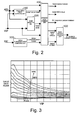
- the mode selection unit 200 computes a target mode based on the accelerator position APO and the vehicle speed VSP using an EV-HEV selection map, which is shown in Figure 4. However, the HEV mode will be forcibly set as the target mode if the state of charge SOC of the battery 4 is at or below a prescribed value.
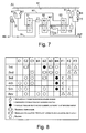
- Figure 7 is a schematic skeleton diagram that shows a power train of the automatic transmission used in the hybrid vehicle drive system.
- Figure 8 is a clutch and brake engagement operating chart based on the automatic transmission AT used in the hybrid vehicle drive system.
- the automatic transmission AT is provided with three simple planetary gear sets G1, G2 and G3.
- the front planetary gear set G1 has a front sun gear S1, a front carrier PC1, and a front ring gear R1 as rotating elements.
- the mid planetary gear set G2 has a mid sun gear S2, a mid carrier PC2, and a mid ring gear R2 as rotating elements.
- the automatic transmission AT has an input shaft IN that receives a rotation drive torque from either the motor/generator MG alone, or from the engine E and the motor/generator MG together via a damper D.
- the automatic transmission AT has an output shaft OUT is an output shaft that outputs a rotation drive torque to the left and right rear drive wheels RL and RR via the automatic transmission AT.
- the automatic transmission AT has a plurality of frictional engagement elements (clutches and brakes) that can be selectively engaged and disengaged such that the power transmission path (e.g., first gear, second gear, etc.) is determined based on the combination of the engaged and disengaged frictional engagement elements.
- the automatic transmission AT transfers the rotation of the input shaft IN to the output shaft OUT after converting the rotation at a gear ratio corresponding to the selected gear.
- the rotation of the output shaft OUT is distributed to the left and right rear drive wheels RL and RR by the differential gear unit DF, the left drive shaft DSL, and the right drive shaft DSR, and thereby contributes to moving the vehicle.
- the friction elements of the automatic transmission AT includes an input clutch C1, a high/low reverse clutch C2, a direct clutch C3, a reverse brake B1, a front brake B2, a low coast brake B3, a forward brake B4, a first one-way clutch F1, a third one-way clutch F2, and a forward one-way clutch F3.
- the clutches of the automatic transmission AT are generally referred to as gear position clutches that are selectively engaged and disengaged to obtain the desired gear position (e.g., 1 st gear, 2 nd gear, 3 rd gear, etc.)
- the input clutch C1 on being released, connects the front ring gear R1 to the input shaft IN, and on being engaged connects the front ring gear R1 and the mid ring gear R2 to the input shaft IN.
- the high/low reverse clutch C2 on being engaged, connects the mid sun gear S2 and the rear sun gear S3.
- the reverse brake B1 on being engaged, secures the rear carrier PC3 in place to a transmission case TC.
- the front brake B2 on being engaged, secures the front sun gear S1 in place to the transmission case TC.
- the first one-way clutch F 1 frees rotation in the forward direction of the rear sun gear S3 with respect to the mid sun gear S2 (i.e., in the same direction of rotation as that of the engine), and locks reverse rotation.
- the third one-way clutch F2 frees rotation in the forward direction of the front sun gear S 1 and locks reverse rotation.
- the forward one-way clutch F3 frees rotation in the forward direction of the mid sun gear S2 and locks reverse rotation.
- the output shaft OUT is directly connected to the mid carrier PC2.
- the front carrier PC 1 and the rear ring gear R3 are directly connected via a first member M1.
- the mid ring gear R2 and the rear carrier PC3 are directly connected via a second member M2.
- the automatic transmission AT reaches first gear via the engagement of the high/low reverse clutch C2, the front brake B2, the low coast brake B3, and the forward brake B4.
- the automatic transmission AT shifts to second gear via the engagement of the direct clutch C3, the front brake B2, the low coast brake B3, and the forward brake B4.
- the automatic transmission AT shifts to third gear via the engagement of the high/low reverse clutch C2, the direct clutch C3, the front brake B2, and the forward brake B4.
- the automatic transmission AT shifts to fourth gear via the engagement of the input clutch C1, the high/low reverse clutch C2, the direct clutch C3, and the forward brake B4.
- the automatic transmission AT shifts to fifth gear via the engagement of the input clutch C1, the high/low reverse clutch C2, the front brake B2, and the forward brake B4.
- the automatic transmission AT shifts to reverse gear via the engagement of the high/low reverse clutch C2, the reverse brake B1, and the front brake B2.
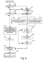
- Figure 9 is a flow chart showing the flow of the engine starting control process executed by the integrated controller 10 of the first embodiment when the vehicle is running under the EV mode. The individual steps are described below (engine starting control). The process starts when an engine starting command is generated when the vehicle is running under the EV mode.
- step S1 the integrated controller 10 determines whether the state of charge SOC of the battery 4 has decreased to a prescribed level. If the answer is Yes, then the process moves to step S2, while if the answer is No, then the process moves to step S7. In other words, when the vehicle is running under the EV mode, in step S1, the integrated controller 10 determines whether the state of charge SOC of the battery 4 has reached or fallen below a prescribed value, whereupon the target mode is forcibly changed by the integrated controller 10 from the EV mode to the HEV mode.
- step S2 following a decision in step S 1 that the state of charge SOC of the battery 4 had decreased to a prescribed level, the integrated controller 10 determines whether the gears of the automatic transmission AT have been shifted when the transition from the EV mode to the HEV mode has been made once the engine E has been started. If the answer is Yes, then the process moves to step S8, and if the answer is No, then the process moves to step S3.
- the gear position clutches that constitute the fourth gear are the input clutch C1, the high/low reverse clutch C2 and the direct clutch C3.
- the integrated controller 10 determines, for example, that the direct clutch C3 among these gear position clutches C1, C2 and C3 is the one with the maximum torque transfer capacity CL_MaxTqu whose capacity is to be controlled.
- step S5 following starting the engine in step S4, the torque transfer capacity control of the selected maximum torque transfer capacity clutch CL_MaxTqu (the second clutch CL2) whose capacity is to be controlled is initiated, whereupon the process moves to step S6.
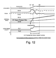
- torque transfer capacity control of the maximum torque transfer capacity clutch reduces the torque transfer capacity of the second clutch CL2 while the engine E is started (refer to the second clutch CL2 torque transfer capacity control characteristics shown in Figures 11 and 12).
- capacity control of the clutch CL_MaxTqu whose capacity is to be controlled is performed by reducing the torque transfer capacity of the second clutch CL2 that is completely engaged in order to hold the gear position while the engine E is started (refer to the CL2 torque transfer capacity control characteristics shown in Figures 10 and 11).
- step S7 following the decision in step S1 that the state of charge SOC of the battery 4 has not decreased below a prescribed level, the integrated controller 10 determines whether a kick-down operation has been performed by the driver (i.e., the driver has fully depressed the accelerator in response to a sudden need for extra speed, and the gear position has shifted to the low side). If the answer is Yes, then the process moves to step S8. However, if the answer is No, then the process moves to step S2 as discussed above.
- a kick-down operation has been performed by the driver (i.e., the driver has fully depressed the accelerator in response to a sudden need for extra speed, and the gear position has shifted to the low side). If the answer is Yes, then the process moves to step S8. However, if the answer is No, then the process moves to step S2 as discussed above.
- step S9 following the determining of the gear positions in step S8, the integrated controller 10 then determines which one of the gear position clutches has a maximum torque transfer capacity from among the gear position clutches in the automatic transmission AT that are engaged in the automatic transmission AT to constitute a gear position immediately prior to the kickdown operation (or before shifting gears) when the vehicle is running under electric drive mode. Then, in step S9, the integrated controller 10 selects the one of the gear position clutches that has the maximum torque transfer capacity from the gear position clutches constituting the gear position immediately prior to the kickdown operation (or before shifting gears) as the second clutch CL2.
- This one of the gear position clutches is then designated as a maximum torque transfer capacity clutch CL_MaxTqu, which is also designated as the second clutch CL2 in Figure 1 before the kickdown operation (or before shifting gears).
- CL_MaxTqu is also designated as the second clutch CL2 in Figure 1 before the kickdown operation (or before shifting gears).
- This one of the gear position clutches is then designated as a maximum torque transfer capacity clutch CL_MaxTquKD, which is also designated as the second clutch CL2 in Figure 1 after the kickdown operation (or after shifting gears).
- CL_MaxTquKD is also designated as the second clutch CL2 in Figure 1 after the kickdown operation (or after shifting gears).
- step S13 following the selection of the maximum torque transfer capacity clutch CL_MaxTqu or CL_MaxTquKD that is to be subjected to capacity control in step S11 or S 12, an engine starting operation is performed as explained below. Once the engine starting operation has began, the process moves to step S5 where torque transfer capacity control of the maximum torque transfer capacity clutch CL_MaxTqu or CL_MaxTquKD is performed.
- the direct clutch C3 which has the maximum torque transfer capacity of these three clutches, was selected as the second clutch CL2.
- the direct clutch C3 that had been selected as the second clutch CL2 was subjected to torque transfer capacity control based on a slip engagement, and when the torque transfer capacity of the direct clutch C3 had decreased from 78.6 [Nm] to 35.2 [Nm], as shown in Figure 10, the torque cut efficiency reached 89.9%.
- the results showed that only approximately 10% of the input torque during the initial combustion of the engine was transmitted to the output shaft OUT of the automatic transmission AT.
- first clutch CL1 rises in the second stage due to the starting of the engine E by slip engagement of the second clutch CL2 after the initiation of engine starting at time t1, and a state of complete engagement is reached at substantially the same time as the conclusion of engine starting at time t2.
- torque transfer capacity of the second clutch CL2 decreases only to a prescribed level (larger than that encountered when the starting was caused by a decrease in the SOC), and is maintained at that reduced level so that fluctuation in the combination of motor torque and engine torque will be minimized.
Landscapes
- Engineering & Computer Science (AREA)
- Mechanical Engineering (AREA)
- Transportation (AREA)
- Chemical & Material Sciences (AREA)
- Combustion & Propulsion (AREA)
- Power Engineering (AREA)
- General Engineering & Computer Science (AREA)
- Automation & Control Theory (AREA)
- Hybrid Electric Vehicles (AREA)
- Control Of Transmission Device (AREA)
- Electric Propulsion And Braking For Vehicles (AREA)
- Control Of Vehicle Engines Or Engines For Specific Uses (AREA)
- Hydraulic Clutches, Magnetic Clutches, Fluid Clutches, And Fluid Joints (AREA)
- Control Of Driving Devices And Active Controlling Of Vehicle (AREA)
Applications Claiming Priority (1)
| Application Number | Priority Date | Filing Date | Title |
|---|---|---|---|
| JP2005324295A JP4341610B2 (ja) | 2005-11-09 | 2005-11-09 | ハイブリッド車両のエンジン再始動制御装置 |
Publications (3)
| Publication Number | Publication Date |
|---|---|
| EP1785305A2 true EP1785305A2 (de) | 2007-05-16 |
| EP1785305A3 EP1785305A3 (de) | 2010-04-28 |
| EP1785305B1 EP1785305B1 (de) | 2011-08-10 |
Family
ID=37709683
Family Applications (1)
| Application Number | Title | Priority Date | Filing Date |
|---|---|---|---|
| EP06255697A Active EP1785305B1 (de) | 2005-11-09 | 2006-11-04 | Hybridfahrzeugsteuerung |
Country Status (5)
| Country | Link |
|---|---|
| US (1) | US7770678B2 (de) |
| EP (1) | EP1785305B1 (de) |
| JP (1) | JP4341610B2 (de) |
| KR (1) | KR100837903B1 (de) |
| CN (1) | CN1962335B (de) |
Cited By (13)
| Publication number | Priority date | Publication date | Assignee | Title |
|---|---|---|---|---|
| WO2008049662A1 (de) * | 2006-10-23 | 2008-05-02 | Robert Bosch Gmbh | Verfahren für die steuerung eines hybridantriebs |
| WO2009021912A1 (de) * | 2007-08-16 | 2009-02-19 | Zf Friedrichshafen Ag | Verfahren zum starten des verbrennungsmotors während einer lastschaltung bei parallelen hybridfahrzeugen |
| WO2008151930A3 (de) * | 2007-06-11 | 2009-03-05 | Bosch Gmbh Robert | Verfahren zum betreiben einer hybrid-antriebsvorrichtung eines fahrzeugs |
| WO2009037239A3 (de) * | 2007-09-22 | 2009-07-23 | Zahnradfabrik Friedrichshafen | Verfahren zum betreiben eines antriebsstrangs |
| EP2308734A1 (de) * | 2009-10-09 | 2011-04-13 | JATCO Ltd | Steuerungsvorrichtung für ein Hybridfahrzeug |
| US8196688B2 (en) | 2007-08-16 | 2012-06-12 | Zf Friedrichshafen Ag | Method for carrying out a tractive-force interrupted shifting in a parallel hybrid vehicle |
| US8246509B2 (en) | 2007-09-22 | 2012-08-21 | Zf Friedrichshafen | Method for operating a drive train |
| US8251865B2 (en) | 2007-08-16 | 2012-08-28 | Zf Friedrichshafen Ag | Method for carrying out a load shift in a parallel hybrid vehicle during hybrid operation |
| US8257223B2 (en) | 2007-08-16 | 2012-09-04 | Zf Friedrichshafen Ag | Method for carrying out a shift during hybrid operation in a parallel hybrid vehicle |
| US8272993B2 (en) | 2007-08-16 | 2012-09-25 | Zf Friedrichshafen Ag | Method for carrying out a load shift in vehicles with electric drive |
| US8328681B2 (en) | 2007-09-22 | 2012-12-11 | Zf Friedrichshafen Ag | Method for operating a drive train |
| FR2988440A1 (fr) * | 2012-03-20 | 2013-09-27 | Porsche Ag | Procede de demarrage de moteur, en particulier d'un moteur de vehicule automobile |
| EP2634053B1 (de) * | 2010-10-28 | 2020-04-08 | Nissan Motor Co., Ltd | Steuervorrichtung für ein hybridfahrzeug |
Families Citing this family (99)
| Publication number | Priority date | Publication date | Assignee | Title |
|---|---|---|---|---|
| DE102004002061A1 (de) * | 2004-01-15 | 2005-08-04 | Zf Friedrichshafen Ag | Verfahren zum Steuern und Regeln eines Antriebsstranges eines Hybridfahrzeuges und Antriebsstrang eines Hybridfahrzeugs |
| US7370715B2 (en) * | 2004-12-28 | 2008-05-13 | Ford Global Technologies, Llc | Vehicle and method for controlling engine start in a vehicle |
| DE102006008640A1 (de) * | 2006-02-24 | 2007-08-30 | Robert Bosch Gmbh | Hybridantrieb mit einem Direktstart unterstützender Trennkupplung |
| DE112007002600A5 (de) * | 2006-11-27 | 2009-08-06 | Luk Lamellen Und Kupplungsbau Beteiligungs Kg | Verfahren und Vorrichtung zum Adaptieren einer Trennkupplung in einem Fahrzeughybridantriebsstrang |
| US8387730B2 (en) * | 2006-11-30 | 2013-03-05 | Azure Dynamics, Inc. | Method and apparatus for starting an engine in a hybrid vehicle |
| US8142328B2 (en) * | 2007-07-05 | 2012-03-27 | Schaeffler Technologies AG & Co. KG | Method for controlling a starting clutch |
| US9109566B2 (en) * | 2007-07-20 | 2015-08-18 | William L. Aldrich, III | Method of smoothing non-driver-commanded restarts of a hybrid vehicle |
| JP5098496B2 (ja) * | 2007-08-02 | 2012-12-12 | 日産自動車株式会社 | ハイブリッド車両の駆動制御装置 |
| DE102007041569A1 (de) * | 2007-09-01 | 2009-03-05 | Zf Friedrichshafen Ag | Verfahren zum Steuern und/oder Regeln einer Hybridantriebsanordnung |
| DE102008039588B4 (de) * | 2007-12-12 | 2016-02-04 | GM Global Technology Operations LLC (n. d. Ges. d. Staates Delaware) | Hybridmaschinensteuersystem sowie Verfahren zum Steuern desselben |
| DE102007055832A1 (de) * | 2007-12-17 | 2009-06-18 | Zf Friedrichshafen Ag | Verfahren und Vorrichtung zum Betrieb eines Hybridantriebes eines Fahrzeuges |
| JP4941360B2 (ja) * | 2008-03-03 | 2012-05-30 | 日産自動車株式会社 | ハイブリッド車両のエンジン始動制御装置 |
| WO2009109831A1 (en) * | 2008-03-03 | 2009-09-11 | Nissan Motor Co., Ltd. | Engine start control system for hybrid vehicle |
| US8212532B2 (en) * | 2008-07-24 | 2012-07-03 | General Electric Company | Method and system for control of a vehicle energy storage device |
| KR101028014B1 (ko) | 2008-10-31 | 2011-04-13 | 현대자동차일본기술연구소 | 하이브리드 차량의 클러치 전달토크 제어 방법 |
| JP5158108B2 (ja) * | 2009-03-04 | 2013-03-06 | 株式会社デンソー | 車両制御装置 |
| JP5340790B2 (ja) * | 2009-04-08 | 2013-11-13 | アイシン・エーアイ株式会社 | 車両の動力伝達制御装置 |
| US8062171B2 (en) * | 2009-05-01 | 2011-11-22 | Ford Global Technologies, Llc | Transmission engagement control during an engine restart of a hybrid electric vehicle |
| US8192324B2 (en) * | 2009-11-13 | 2012-06-05 | Ford Global Technologies, Llc | Vehicle and method for controlling engine start in a vehicle |
| US8565990B2 (en) * | 2009-11-13 | 2013-10-22 | Ford Global Technologies, Llc. | Vehicle and method for controlling engine start in a vehicle |
| KR20110139953A (ko) | 2010-06-24 | 2011-12-30 | 현대자동차주식회사 | 하이브리드 차량의 시동제어장치 및 방법 |
| JP5382223B2 (ja) * | 2010-07-21 | 2014-01-08 | 日産自動車株式会社 | ハイブリッド車両の制御装置 |
| KR20120021093A (ko) * | 2010-08-31 | 2012-03-08 | 현대자동차주식회사 | 하이브리드 차량의 변속 제어장치 및 방법 |
| KR20120021094A (ko) * | 2010-08-31 | 2012-03-08 | 현대자동차주식회사 | 하이브리드 차량의 변속 제어장치 및 방법 |
| KR101209731B1 (ko) * | 2010-09-17 | 2012-12-07 | 현대자동차주식회사 | 하이브리드 차량의 제어장치 및 방법 |
| JP2012086784A (ja) * | 2010-10-22 | 2012-05-10 | Nissan Motor Co Ltd | ハイブリッド車両の変速制御装置 |
| DE102010050123A1 (de) * | 2010-11-03 | 2012-05-03 | Audi Ag | Kraftfahrzeug mit einem Hybridantrieb und Verfahren zur Auswahl einer Elektromaschine und/oder eines Anlassers zum Anlassen eines Verbrennungsmotors |
| US8574125B2 (en) | 2010-12-30 | 2013-11-05 | Ford Global Technologies, Llc | Methods and systems for assisted direct start control |
| EP2664510B1 (de) * | 2011-01-12 | 2016-12-07 | Toyota Jidosha Kabushiki Kaisha | Steuervorrichtung für ein hybridfahrzeug |
| CN103402809B (zh) | 2011-01-13 | 2016-11-09 | 卡明斯公司 | 用于控制混合动力传动系中的功率输出分布的系统、方法和装置 |
| GB2487733B (en) * | 2011-02-01 | 2018-01-24 | Jaguar Land Rover Ltd | Hybrid electric vehicle controller and method of controlling a hybrid electric vehicle |
| JP5465197B2 (ja) * | 2011-02-03 | 2014-04-09 | ジヤトコ株式会社 | ハイブリッド車両の制御装置 |
| US8552575B2 (en) | 2011-04-03 | 2013-10-08 | Tma Power, Llc | Hybrid electric power for vehicular propulsion |
| CN103534156B (zh) * | 2011-06-30 | 2016-08-31 | 日产自动车株式会社 | 混合动力车辆的控制装置 |
| WO2013005844A1 (ja) | 2011-07-06 | 2013-01-10 | アイシン・エィ・ダブリュ株式会社 | 制御装置 |
| JP5807560B2 (ja) * | 2011-07-06 | 2015-11-10 | アイシン・エィ・ダブリュ株式会社 | 制御装置 |
| JP2013018391A (ja) * | 2011-07-12 | 2013-01-31 | Aisin Ai Co Ltd | 車両の動力伝達制御装置 |
| JP5472227B2 (ja) * | 2011-08-08 | 2014-04-16 | アイシン・エィ・ダブリュ株式会社 | 制御装置 |
| JP5553175B2 (ja) * | 2011-08-30 | 2014-07-16 | アイシン・エィ・ダブリュ株式会社 | 制御装置 |
| JP2012121568A (ja) * | 2012-01-10 | 2012-06-28 | Nissan Motor Co Ltd | ハイブリッド車両のエンジン始動制御装置 |
| US8834320B2 (en) * | 2012-01-11 | 2014-09-16 | Ford Global Technologies, Llc | Hybrid vehicle and control for a clutch engaging event |
| DE112013000310B4 (de) * | 2012-02-24 | 2021-09-16 | Aisin Aw Co., Ltd. | Steuervorrichtung |
| WO2013125693A1 (ja) * | 2012-02-24 | 2013-08-29 | アイシン・エィ・ダブリュ株式会社 | 制御装置 |
| US9358872B2 (en) * | 2012-05-07 | 2016-06-07 | Ford Global Technologies, Llc | Controlling a powertrain and a clutch of a vehicle |
| US9790871B2 (en) | 2012-09-19 | 2017-10-17 | Yamaha Hatsudoki Kabushiki Kaisha | Control apparatus for vehicle, vehicle, and motor |
| US20150246670A1 (en) * | 2012-09-21 | 2015-09-03 | Toyota Jidosha Kabushiki Kaisha | Vehicle control apparatus |
| WO2014054813A1 (ja) * | 2012-10-05 | 2014-04-10 | アイシン・エィ・ダブリュ株式会社 | 車輌用駆動装置の制御装置 |
| KR101846569B1 (ko) * | 2012-10-26 | 2018-04-09 | 현대자동차주식회사 | 하이브리드 차량의 제어방법 |
| CN104884326B (zh) * | 2012-12-26 | 2017-06-23 | 日产自动车株式会社 | 混合动力车辆的控制装置 |
| EP2969684B1 (de) | 2013-03-14 | 2025-05-07 | Allison Transmission, Inc. | System und verfahren zur kompensation eines turboloches bei hybridfahrzeugen |
| WO2014158826A1 (en) | 2013-03-14 | 2014-10-02 | Allison Transmission, Inc. | System and method for engine driveline disconnect during regeneration in hybrid vehicles |
| CN105102287B (zh) | 2013-03-14 | 2019-04-12 | 艾里逊变速箱公司 | 用于混合动力电动车再生模式期间能量管理的系统和方法 |
| EP2969681B1 (de) | 2013-03-14 | 2021-02-24 | Allison Transmission, Inc. | System und verfahren zur optimierung von nutzungsbeschränkungen einer hybridfahrzeugbatterie |
| CN105142963B (zh) | 2013-03-15 | 2018-02-06 | 艾里逊变速箱公司 | 用于平衡混合动力车辆中的能量存储模块的荷电状态的系统及方法 |
| KR102116701B1 (ko) | 2013-03-15 | 2020-06-01 | 알리손 트랜스미션, 인크. | 하이브리드 자동차들을 위한 서비스 차단 인터로크 시스템 및 방법 |
| EP2969683A4 (de) | 2013-03-15 | 2017-01-25 | Allison Transmission, Inc. | System und verfahren für energieratenausgleich in hybriden automatischen getrieben |
| JP6003843B2 (ja) * | 2013-08-08 | 2016-10-05 | トヨタ自動車株式会社 | ハイブリッド車両の制御装置 |
| US9108615B2 (en) * | 2013-09-19 | 2015-08-18 | Borgwarner Inc. | Multimode clutch for a parallel hybrid vehicle |
| DE102014213080A1 (de) * | 2013-09-20 | 2015-04-16 | Robert Bosch Gmbh | Verfahren zum Abstellen einer Brennkraftmaschine |
| US9568082B2 (en) | 2014-01-30 | 2017-02-14 | Byd Company Limited | Power transmission system for vehicle and vehicle comprising the same |
| CN104279311B (zh) * | 2014-01-30 | 2015-11-25 | 比亚迪股份有限公司 | 车辆中同步器的控制方法及车辆 |
| CN104276031B (zh) | 2014-01-30 | 2016-01-13 | 比亚迪股份有限公司 | 车辆及其驱动控制方法 |
| WO2015113415A1 (en) | 2014-01-30 | 2015-08-06 | Byd Company Limited | Power transmission system for vehicle and vehicle comprising the same |
| WO2015113416A1 (en) | 2014-01-30 | 2015-08-06 | Byd Company Limited | Power transmission system for vehicle and vehicle comprising the same |
| US9568080B2 (en) | 2014-01-30 | 2017-02-14 | Byd Company Limited | Power transmission system for vehicle and vehicle comprising the same |
| US10670123B2 (en) | 2014-01-30 | 2020-06-02 | Byd Company Limited | Power transmission system for vehicle and vehicle comprising the same |
| US9688268B2 (en) * | 2014-06-12 | 2017-06-27 | Ford Global Technologies, Llc | Method for controlling an electric machine in a vehicle with an engine disconnect clutch |
| DE102014214715A1 (de) * | 2014-07-25 | 2016-01-28 | Robert Bosch Gmbh | Verfahren und Vorrichtung zum Betreiben eines hybriden Antriebssystems |
| US9714027B2 (en) | 2014-08-18 | 2017-07-25 | Ford Global Technologies, Llc | Methods and systems for starting an engine |
| US9533677B2 (en) * | 2014-08-26 | 2017-01-03 | Ford Global Technologies, Llc | Method of transitioning among shift schedules |
| EP2995487B1 (de) | 2014-09-10 | 2019-02-13 | BYD Company Limited | Kraftübertragungssystem und fahrzeug damit |
| WO2016037469A1 (en) | 2014-09-10 | 2016-03-17 | Byd Company Limited | Transmission unit, power transmission system and vehicle comprising the same |
| WO2016037468A1 (en) | 2014-09-10 | 2016-03-17 | Byd Company Limited | Power transmission system and vehicle comprising the same |
| CN104608760B (zh) | 2014-10-20 | 2016-05-25 | 比亚迪股份有限公司 | 混合动力汽车及其换挡控制方法、动力传动系统 |
| US10166973B2 (en) | 2014-10-20 | 2019-01-01 | Byd Company Limited | Vehicle and shifting control method and power transmission system thereof |
| US9499164B2 (en) * | 2014-11-19 | 2016-11-22 | Ford Global Technologies, Llc | Controlling a clutch between an engine and a motor during a shift event in a hybrid vehicle |
| CN104590265B (zh) * | 2014-11-28 | 2017-08-08 | 重庆小康工业集团股份有限公司 | 一种电动车两档变速器自动换档的控制方法及其控制系统 |
| CN104773063B (zh) | 2015-01-16 | 2015-12-02 | 比亚迪股份有限公司 | 变速器、动力传动系统和车辆 |
| US10166853B2 (en) | 2015-01-16 | 2019-01-01 | Byd Company Limited | Transmission unit, power transmission system and vehicle comprising the same |
| WO2016112655A1 (en) | 2015-01-16 | 2016-07-21 | Byd Company Limited | Power transmission system and vehicle comprising the same |
| US9889733B2 (en) | 2015-01-16 | 2018-02-13 | Byd Company Limited | Power transmission system and vehicle comprising the same |
| JP6470621B2 (ja) | 2015-04-03 | 2019-02-13 | 株式会社エフ・シー・シー | ハイブリッド車両の動力伝達装置 |
| JP6256405B2 (ja) * | 2015-04-10 | 2018-01-10 | トヨタ自動車株式会社 | ハイブリッド車両 |
| CN105172571B (zh) * | 2015-08-12 | 2017-12-12 | 奇瑞汽车股份有限公司 | 一种混合动力汽车驱动系统及其驱动方法 |
| DE112016002555T5 (de) * | 2015-09-18 | 2018-02-22 | Aisin Aw Co., Ltd. | Steuerungsvorrichtung |
| DE102015220430A1 (de) * | 2015-10-20 | 2017-04-20 | Zf Friedrichshafen Ag | Kraftfahrzeug |
| KR101714239B1 (ko) * | 2015-10-21 | 2017-03-09 | 현대자동차주식회사 | 차량용 클러치 제어방법 |
| EP3184344B1 (de) * | 2015-12-23 | 2018-07-18 | Volvo Car Corporation | Achse mit einem hybridantriebsmodul |
| US9914449B2 (en) * | 2016-01-13 | 2018-03-13 | Ford Global Technologies, Llc | Methods and system for improving efficiency of a hybrid vehicle |
| US10597024B2 (en) * | 2016-03-10 | 2020-03-24 | Ford Global Technologies, Llc | System and method for powering start-stop and hybrid vehicle components and accessories |
| DE102016206735A1 (de) * | 2016-04-21 | 2017-10-26 | Zf Friedrichshafen Ag | Verfahren zum Betrieb eines Antriebsstranges eines Kraftfahrzeugs, und Antriebsstrangmodul eines solchen Kraftfahrzeugs |
| US10407053B2 (en) * | 2017-02-28 | 2019-09-10 | Ford Global Technologies, Llc | Systems and methods for hybrid vehicle launch |
| DE102017214787A1 (de) * | 2017-08-23 | 2019-02-28 | Bayerische Motoren Werke Aktiengesellschaft | Impulsstart in einem Hybrid-Antriebsstrang |
| JP6972923B2 (ja) * | 2017-10-27 | 2021-11-24 | いすゞ自動車株式会社 | 制御装置 |
| KR102610753B1 (ko) * | 2018-12-11 | 2023-12-08 | 현대자동차주식회사 | 하이브리드 차량 제어 장치, 그를 포함한 시스템 및 그 방법 |
| US10988133B2 (en) * | 2019-02-18 | 2021-04-27 | Ford Global Technologies, Llc | Vehicle exhaust sound control systems and methods |
| CN111746259A (zh) * | 2019-03-29 | 2020-10-09 | 乾碳国际公司 | 重卡节油机器人装置和控制方法 |
| CN113753018A (zh) * | 2021-10-25 | 2021-12-07 | 吉林大学 | 轮毂液驱混动商用车动力域动态协调控制方法 |
| US12179741B2 (en) * | 2022-02-23 | 2024-12-31 | Ford Global Technologies, Llc | Adaptive controls of engine disconnect clutch |
Citations (3)
| Publication number | Priority date | Publication date | Assignee | Title |
|---|---|---|---|---|
| JPH1182260A (ja) | 1997-08-29 | 1999-03-26 | Aisin Aw Co Ltd | 車両用ハイブリッド駆動装置 |
| JP2003004138A (ja) | 2001-06-25 | 2003-01-08 | Toyota Motor Corp | 動力装置 |
| DE10327306A1 (de) | 2003-06-18 | 2005-01-05 | Daimlerchrysler Ag | Verfahren zum Betreiben einer Antriebseinheit eines Kraftfahrzeugs |
Family Cites Families (21)
| Publication number | Priority date | Publication date | Assignee | Title |
|---|---|---|---|---|
| JP2896225B2 (ja) * | 1990-11-20 | 1999-05-31 | アイシン・エィ・ダブリュ株式会社 | ホイールモータの潤滑装置 |
| US5472059A (en) * | 1994-02-15 | 1995-12-05 | Dana Corporation | Wheel end assembly |
| US5982045A (en) * | 1996-04-19 | 1999-11-09 | Toyota Jidosha Kabushiki Kaisha | Hybrid vehicle drive system adapted to prevent concurrent mode change and transmission shifting or torque distribution ratio change |
| JP3775012B2 (ja) * | 1997-08-29 | 2006-05-17 | アイシン・エィ・ダブリュ株式会社 | 車両用ハイブリッド駆動装置 |
| JP3864582B2 (ja) | 1998-10-20 | 2007-01-10 | トヨタ自動車株式会社 | エンジンの自動停止始動装置 |
| JP2000074202A (ja) | 1998-08-26 | 2000-03-14 | Toyota Motor Corp | 変速機の変速制御装置 |
| JP2000255285A (ja) | 1999-03-09 | 2000-09-19 | Mitsubishi Motors Corp | ハイブリッド車両 |
| JP3663962B2 (ja) | 1999-03-16 | 2005-06-22 | トヨタ自動車株式会社 | 車両のエンジン再始動時の制御装置 |
| IT1320579B1 (it) * | 2000-08-02 | 2003-12-10 | Fiat Ricerche | Procedimento e sistema di controllo della propulsione di unautoveicolo. |
| JP4648587B2 (ja) | 2001-07-18 | 2011-03-09 | 本田技研工業株式会社 | 動力伝達装置におけるエンジン再始動発進制御装置 |
| JP3765399B2 (ja) * | 2001-11-01 | 2006-04-12 | 本田技研工業株式会社 | 内燃機関の潤滑油供給構造 |
| JP3771213B2 (ja) * | 2002-11-19 | 2006-04-26 | 本田技研工業株式会社 | ハイブリッド車両のクラッチ制御装置 |
| JP4281417B2 (ja) | 2003-05-29 | 2009-06-17 | 日産自動車株式会社 | 車両のアイドルストップ制御装置 |
| JP2005098392A (ja) | 2003-09-25 | 2005-04-14 | Mitsubishi Motors Corp | トルクコンバータの油圧制御装置 |
| JP3800218B2 (ja) * | 2003-10-16 | 2006-07-26 | 日産自動車株式会社 | ハイブリッド車両の変速制御装置 |
| DE102004002061A1 (de) * | 2004-01-15 | 2005-08-04 | Zf Friedrichshafen Ag | Verfahren zum Steuern und Regeln eines Antriebsstranges eines Hybridfahrzeuges und Antriebsstrang eines Hybridfahrzeugs |
| US7351182B2 (en) * | 2004-10-27 | 2008-04-01 | Aisin Aw Co., Ltd. | Drive apparatus for hybrid vehicle and control method thereof |
| US7370715B2 (en) * | 2004-12-28 | 2008-05-13 | Ford Global Technologies, Llc | Vehicle and method for controlling engine start in a vehicle |
| JP4341611B2 (ja) * | 2005-11-09 | 2009-10-07 | 日産自動車株式会社 | ハイブリッド車両のエンジン再始動制御装置 |
| JP4466514B2 (ja) * | 2005-09-08 | 2010-05-26 | 日産自動車株式会社 | ハイブリッド車両のエンジン始動制御装置 |
| JP2007126081A (ja) * | 2005-11-07 | 2007-05-24 | Nissan Motor Co Ltd | ハイブリッド車両のクラッチ伝達トルク容量制御装置 |
-
2005
- 2005-11-09 JP JP2005324295A patent/JP4341610B2/ja not_active Expired - Fee Related
-
2006
- 2006-11-04 EP EP06255697A patent/EP1785305B1/de active Active
- 2006-11-08 US US11/594,246 patent/US7770678B2/en active Active
- 2006-11-09 CN CN2006101385543A patent/CN1962335B/zh active Active
- 2006-11-09 KR KR1020060110347A patent/KR100837903B1/ko not_active Expired - Fee Related
Patent Citations (3)
| Publication number | Priority date | Publication date | Assignee | Title |
|---|---|---|---|---|
| JPH1182260A (ja) | 1997-08-29 | 1999-03-26 | Aisin Aw Co Ltd | 車両用ハイブリッド駆動装置 |
| JP2003004138A (ja) | 2001-06-25 | 2003-01-08 | Toyota Motor Corp | 動力装置 |
| DE10327306A1 (de) | 2003-06-18 | 2005-01-05 | Daimlerchrysler Ag | Verfahren zum Betreiben einer Antriebseinheit eines Kraftfahrzeugs |
Cited By (18)
| Publication number | Priority date | Publication date | Assignee | Title |
|---|---|---|---|---|
| US8529399B2 (en) | 2006-10-23 | 2013-09-10 | Robert Bosch Gmbh | Method for controlling a hybrid drive |
| WO2008049662A1 (de) * | 2006-10-23 | 2008-05-02 | Robert Bosch Gmbh | Verfahren für die steuerung eines hybridantriebs |
| WO2008151930A3 (de) * | 2007-06-11 | 2009-03-05 | Bosch Gmbh Robert | Verfahren zum betreiben einer hybrid-antriebsvorrichtung eines fahrzeugs |
| US8257223B2 (en) | 2007-08-16 | 2012-09-04 | Zf Friedrichshafen Ag | Method for carrying out a shift during hybrid operation in a parallel hybrid vehicle |
| WO2009021912A1 (de) * | 2007-08-16 | 2009-02-19 | Zf Friedrichshafen Ag | Verfahren zum starten des verbrennungsmotors während einer lastschaltung bei parallelen hybridfahrzeugen |
| DE102007038771B4 (de) | 2007-08-16 | 2025-03-20 | Zf Friedrichshafen Ag | Verfahren zum Starten des Verbrennungsmotors während einer Lastschaltung bei parallelen Hybridfahrzeugen |
| US8196688B2 (en) | 2007-08-16 | 2012-06-12 | Zf Friedrichshafen Ag | Method for carrying out a tractive-force interrupted shifting in a parallel hybrid vehicle |
| US8272993B2 (en) | 2007-08-16 | 2012-09-25 | Zf Friedrichshafen Ag | Method for carrying out a load shift in vehicles with electric drive |
| US8251865B2 (en) | 2007-08-16 | 2012-08-28 | Zf Friedrichshafen Ag | Method for carrying out a load shift in a parallel hybrid vehicle during hybrid operation |
| US8251866B2 (en) | 2007-08-16 | 2012-08-28 | Zf Friedrichshafen Ag | Method for starting the combustion engine during a load shift in parallel hybrid vehicles |
| US8328681B2 (en) | 2007-09-22 | 2012-12-11 | Zf Friedrichshafen Ag | Method for operating a drive train |
| US8246509B2 (en) | 2007-09-22 | 2012-08-21 | Zf Friedrichshafen | Method for operating a drive train |
| US8123657B2 (en) | 2007-09-22 | 2012-02-28 | Zf Friedrichshafen Ag | Method for the operation of a drive train |
| WO2009037239A3 (de) * | 2007-09-22 | 2009-07-23 | Zahnradfabrik Friedrichshafen | Verfahren zum betreiben eines antriebsstrangs |
| US8386107B2 (en) | 2009-10-09 | 2013-02-26 | Jatco Ltd | Control apparatus for hybrid vehicle |
| EP2308734A1 (de) * | 2009-10-09 | 2011-04-13 | JATCO Ltd | Steuerungsvorrichtung für ein Hybridfahrzeug |
| EP2634053B1 (de) * | 2010-10-28 | 2020-04-08 | Nissan Motor Co., Ltd | Steuervorrichtung für ein hybridfahrzeug |
| FR2988440A1 (fr) * | 2012-03-20 | 2013-09-27 | Porsche Ag | Procede de demarrage de moteur, en particulier d'un moteur de vehicule automobile |
Also Published As
| Publication number | Publication date |
|---|---|
| US20070102211A1 (en) | 2007-05-10 |
| US7770678B2 (en) | 2010-08-10 |
| CN1962335A (zh) | 2007-05-16 |
| EP1785305B1 (de) | 2011-08-10 |
| EP1785305A3 (de) | 2010-04-28 |
| JP4341610B2 (ja) | 2009-10-07 |
| JP2007131070A (ja) | 2007-05-31 |
| KR100837903B1 (ko) | 2008-06-13 |
| CN1962335B (zh) | 2010-05-12 |
| KR20070049987A (ko) | 2007-05-14 |
Similar Documents
| Publication | Publication Date | Title |
|---|---|---|
| EP1785305B1 (de) | Hybridfahrzeugsteuerung | |
| EP1792800B1 (de) | Steuerung für Hybrid-Fahrzeug | |
| EP2247482B1 (de) | Traktionsregelungssystem für ein fahrzeug | |
| EP2669132B1 (de) | Steuervorrichtung für ein hybridfahrzeug | |
| US8798838B2 (en) | Hybrid vehicle control device | |
| EP1859982B1 (de) | Schaltungssteuerung | |
| JP5176421B2 (ja) | ハイブリッド車両の制御装置 | |
| EP2595849B1 (de) | Vorrichtung und verfahren zur steuerung von hybridfahrzeugen | |
| EP2484570B1 (de) | Steuerungsvorrichtung für ein Hybridfahrzeug | |
| US20080017427A1 (en) | Hybrid vehicle control apparatus | |
| EP1839987A2 (de) | Antriebsmodussteuerung | |
| JP4935797B2 (ja) | 電動車の制御装置 | |
| JP5789997B2 (ja) | ハイブリッド車輌の制御装置 | |
| JP2008094332A (ja) | 車両の制御装置 | |
| JP5549144B2 (ja) | 電動車両の制御装置 | |
| JP2005127332A (ja) | 複数の原動機を備えた車両の制御装置 | |
| JP5104061B2 (ja) | 車両の変速制御装置 | |
| JP6004026B2 (ja) | 電動車両の制御装置 | |
| JP5338332B2 (ja) | ハイブリッド車両の制御装置 |
Legal Events
| Date | Code | Title | Description |
|---|---|---|---|
| PUAI | Public reference made under article 153(3) epc to a published international application that has entered the european phase |
Free format text: ORIGINAL CODE: 0009012 |
|
| AK | Designated contracting states |
Kind code of ref document: A2 Designated state(s): AT BE BG CH CY CZ DE DK EE ES FI FR GB GR HU IE IS IT LI LT LU LV MC NL PL PT RO SE SI SK TR |
|
| AX | Request for extension of the european patent |
Extension state: AL BA HR MK YU |
|
| PUAL | Search report despatched |
Free format text: ORIGINAL CODE: 0009013 |
|
| AK | Designated contracting states |
Kind code of ref document: A3 Designated state(s): AT BE BG CH CY CZ DE DK EE ES FI FR GB GR HU IE IS IT LI LT LU LV MC NL PL PT RO SE SI SK TR |
|
| AX | Request for extension of the european patent |
Extension state: AL BA HR MK RS |
|
| RIC1 | Information provided on ipc code assigned before grant |
Ipc: B60W 20/00 20060101AFI20100324BHEP |
|
| 17P | Request for examination filed |
Effective date: 20101018 |
|
| 17Q | First examination report despatched |
Effective date: 20101112 |
|
| AKX | Designation fees paid |
Designated state(s): DE FR GB |
|
| RIC1 | Information provided on ipc code assigned before grant |
Ipc: B60W 20/00 20060101AFI20110131BHEP Ipc: B60K 6/48 20071001ALN20110131BHEP |
|
| GRAP | Despatch of communication of intention to grant a patent |
Free format text: ORIGINAL CODE: EPIDOSNIGR1 |
|
| GRAS | Grant fee paid |
Free format text: ORIGINAL CODE: EPIDOSNIGR3 |
|
| GRAA | (expected) grant |
Free format text: ORIGINAL CODE: 0009210 |
|
| AK | Designated contracting states |
Kind code of ref document: B1 Designated state(s): DE FR GB |
|
| REG | Reference to a national code |
Ref country code: GB Ref legal event code: FG4D |
|
| REG | Reference to a national code |
Ref country code: DE Ref legal event code: R096 Ref document number: 602006023641 Country of ref document: DE Effective date: 20111006 |
|
| PLBE | No opposition filed within time limit |
Free format text: ORIGINAL CODE: 0009261 |
|
| STAA | Information on the status of an ep patent application or granted ep patent |
Free format text: STATUS: NO OPPOSITION FILED WITHIN TIME LIMIT |
|
| 26N | No opposition filed |
Effective date: 20120511 |
|
| REG | Reference to a national code |
Ref country code: DE Ref legal event code: R097 Ref document number: 602006023641 Country of ref document: DE Effective date: 20120511 |
|
| REG | Reference to a national code |
Ref country code: FR Ref legal event code: PLFP Year of fee payment: 10 |
|
| REG | Reference to a national code |
Ref country code: FR Ref legal event code: PLFP Year of fee payment: 11 |
|
| REG | Reference to a national code |
Ref country code: FR Ref legal event code: PLFP Year of fee payment: 12 |
|
| REG | Reference to a national code |
Ref country code: FR Ref legal event code: PLFP Year of fee payment: 13 |
|
| PGFP | Annual fee paid to national office [announced via postgrant information from national office to epo] |
Ref country code: DE Payment date: 20251022 Year of fee payment: 20 |
|
| PGFP | Annual fee paid to national office [announced via postgrant information from national office to epo] |
Ref country code: GB Payment date: 20251023 Year of fee payment: 20 |
|
| PGFP | Annual fee paid to national office [announced via postgrant information from national office to epo] |
Ref country code: FR Payment date: 20251023 Year of fee payment: 20 |