EP1785308B1 - Schaltersteuerung im Fahrzeuginnenraum - Google Patents
Schaltersteuerung im Fahrzeuginnenraum Download PDFInfo
- Publication number
- EP1785308B1 EP1785308B1 EP07003664A EP07003664A EP1785308B1 EP 1785308 B1 EP1785308 B1 EP 1785308B1 EP 07003664 A EP07003664 A EP 07003664A EP 07003664 A EP07003664 A EP 07003664A EP 1785308 B1 EP1785308 B1 EP 1785308B1
- Authority
- EP
- European Patent Office
- Prior art keywords
- image data
- switch
- indication
- driver
- image
- Prior art date
- Legal status (The legal status is an assumption and is not a legal conclusion. Google has not performed a legal analysis and makes no representation as to the accuracy of the status listed.)
- Expired - Lifetime
Links
- 238000013500 data storage Methods 0.000 claims description 23
- 230000015572 biosynthetic process Effects 0.000 claims description 12
- 238000003786 synthesis reaction Methods 0.000 claims description 12
- 230000002542 deteriorative effect Effects 0.000 description 2
- 238000010586 diagram Methods 0.000 description 2
- 230000003213 activating effect Effects 0.000 description 1
- 230000006866 deterioration Effects 0.000 description 1
- 230000000694 effects Effects 0.000 description 1
- 239000004973 liquid crystal related substance Substances 0.000 description 1
Images


Classifications
-
- B—PERFORMING OPERATIONS; TRANSPORTING
- B60—VEHICLES IN GENERAL
- B60K—ARRANGEMENT OR MOUNTING OF PROPULSION UNITS OR OF TRANSMISSIONS IN VEHICLES; ARRANGEMENT OR MOUNTING OF PLURAL DIVERSE PRIME-MOVERS IN VEHICLES; AUXILIARY DRIVES FOR VEHICLES; INSTRUMENTATION OR DASHBOARDS FOR VEHICLES; ARRANGEMENTS IN CONNECTION WITH COOLING, AIR INTAKE, GAS EXHAUST OR FUEL SUPPLY OF PROPULSION UNITS IN VEHICLES
- B60K35/00—Instruments specially adapted for vehicles; Arrangement of instruments in or on vehicles
- B60K35/10—Input arrangements, i.e. from user to vehicle, associated with vehicle functions or specially adapted therefor
Definitions
- the present invention relates to an in-car switch controller for controlling an electronic device disposed in a car.
- switches for selecting functions and adjusting the functions are usually provided in a front panel or in the vicinity thereof.
- a driver encounters difficulty in adjusting the switches while maintaining a driving posture, and must change his posture in order to adjust a switch. Further, the driver actuates a switch while visually ascertaining the functions of the switches located on the switch controller, thereby deteriorating the driver's concentration on his driving, thus creating a safety hazard.
- the present invention relates to an in-car switch controller for controlling an audio system or a like device mounted in a car.
- switches for selecting functions and adjusting the functions are usually provided in a front panel or in the vicinity thereof.
- a driver encounters difficulty in adjusting the switches while maintaining a driving posture, and must change his posture in order to adjust a switch. Further, the driver actuates a switch while visually ascertaining the functions of the switches located on the switch controller, thereby deteriorating the driver's concentration on his driving, thus creating a safety hazard.
- the present invention relates to an in-car switch controller for controlling an audio system or a like device mounted in a car.
- switches for selecting functions and adjusting the functions are usually provided in a front panel or in the vicinity thereof. Many switches are provided, including switches which are rarely used under ordinary circumstances.
- a driver encounters difficulty in adjusting the switches while maintaining a driving posture, and must change his posture in order to adjust a switch. Further, since numerous switches are provided on the front panel, ascertaining a desired switch results in deterioration of the driver's concentration on his driving, thus creating a safety hazard.
- US -A 4 818 048 discloses a head-up holographic display for providing a display of a control panel and indications of the manual operations by a vehicle operator wherein the display includes several hologram layers that are selectively illuminated in response to output signals from a control panel. Moreover, this document discloses the employment of a sensor to detect inputs on the panel and to output corresponding signals to a microprocessor that controls an according operation.
- DE 196 53 595 C1 discloses the employment of a video camera installed in a vehocular cabin and adapted to photograph a user panel and to display the operation elements of the user panel
- the present invention has been conceived to solve the drawback of the background art and is aimed at providing an in-car switch controller which does not raise any problem in driving and offers safety and excellent operability.
- an in-car switch controller which enables a driver to control electronic devices provided in a car, the controller comprising:
- the image data storage section stores a plurality of sets of indication image data corresponding to an image of the switch array, and the switch has the function of designating a set of indication image data for each type of device to be controlled, so as to correspond to the indication of the switch's image. Further, the control section has indication image data designation means which receives an operation signal from the switch, to thereby instruct the indication image data storage section to read image data in order to update the set of indication image data to the specific indication image set.
- the image synthesis section is configured to continuously receive image data photographed by the CCD camera and to receive indication image data each time the indication image data storage section reads new image data; and the image synthesis section is configured to update the synthesized image data each time the indication image data storage section reads new image data.
- FIG. 1 is a perspective view showing an example state in which the in-car switch controller of the present invention is provided in a car.
- reference numeral 21 designates a switch panel.
- the switch panel 21 comprises a power switch 22 for turning on or off power to the in-car switch controller, which will be described later and a switch array 23.
- a plurality of function selection switches 24 are arranged on the switch array 23.
- the switch panel 21 is disposed at the side of a seat 25 of a driver A so that the driver A can actuate the switches. Specific functions are allocated to the respective switches 24, and the driver A selects or controls the function of unillustrated audio equipment by designation of the functions allocated to the respective switches 24.
- Reference numeral 26 designates a CCD camera mounted at an angle on a ceiling 27 of the vehicle body at a position close to the front end of the driver' s seat 25.
- the CCD camera 26 has a predetermined field of view, as designated by chain lines shown in FIG. 6, and successively photographs the switch array 23 and the driver's action including the movement of the driver's hand "a" performed for activating a switch 24.
- Reference numeral 28 designates a display section equipped with a liquid crystal panel.
- the display section 28 is mounted on the top of the front panel 29 and is located within the driver A's view field as designated by chain lines.
- the driver A can view the display section 28 while maintaining an ordinary driving posture.
- An image captured by the CCD camera 26 is sequentially displayed on the display section 28.
- the view field of the CCD camera 26 is dark, as would be the case at night, the area surrounding the view field is illuminated.
- infrared rays emitted from the CCD camera 26 are radiated onto the field of view, thereby enabling infrared-ray photography.
- FIG. 2 is a block diagram showing an example configuration of the in-car switch controller of the present invention.
- MP designates a main control section of the in-car switch controller which consists primarily of a microprocessor and which, upon receipt of an operation signal output from the switch 24 of the switch array 23, controls individual sections shown in FIG. 2 according to a program.
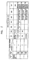
- FIG. 3 shows the contents of the data stored in the image data storage section ROM.
- the image data storage section ROM stores, as image data which are assigned an address (address 21) as a result of actuation of the power switch 22 (a first step), character data "CASSETTE PLAYER” allocated to the switch number S21, character data "RADIO” allocated to the switch number S22, character data "TV” allocated to the switch number S23, and character data "END" allocated to the switch number S27.
- the image data storage section ROM stores, as image data which are assigned an address (address 22) as a result of successive actuation of the power switch 22 and, for example, the switch number S21 (a second step), character data "START" allocated to the switch number S21, indication mark image data allocated to the switch number S21, character data "STOP" allocated to the switch number S22, similar character data allocated to the respective switches S23 to S26, and character data "RETURN TO SCREEN DISPLAY" allocated to the switch number S27.
- the image data storage section ROM stores character data allocated to address 23 in step 22 and character data allocated to address 24 in step 22.
- AD in FIG. 2 designates indication image data designation means for addressing the image data storage section ROM and is controlled by the main control section MP.
- the images data storage section ROM is assigned an address on the basis of the conditions under which the power switch 22 and the switch numbers S21 through S27 are actuated, as has been described above, thereby updating the indication image data sets to a specific indication data image set.
- CO in FIG. 2 designates an image synthesis section, where image data pertaining to the switch array 23 photographed by the CCD camera 26 and indication image data stored in the indication image data storage section ROM are merged into a single set of image data.
- the image synthesis section CO continuously receives, as the image data photographed by the CCD camera 26.
- the image synthesis section CO receives the indication image data each time the indication image data storage section ROM reads new image data.
- the image synthesis section CO updates synthesized image data and delivers the thus-updated synthesized image data to the display section 28. Further, information about updating of each set of synthesized data is delivered to the main control section MP.
- the orientation of the camera is adjusted such that a photographed image is located appropriately in relation to the indication image.
- B21, B22, and B23 in FIG. 2 designate electronic equipment disposed in the car; that is, a cassette player, a radio, and a TV set.
- C21, C22, and C23 designate electronic switch sections; C21 turns on/off connection to one terminal of a function switch of the electronic equipment B21, C22 turns on/off connection to one terminal of a function switch of the electronic equipment B22, and C23 turns on/off connection to one terminal of a function switch of the electronic equipment B23.
- OUT designates an output control section for controlling the electronic switches C21, C22 and C23 and is controlled by the main control section MP according to a program.
- the main control section MP Upon receipt of a signal from the switch 24 or a signal output from the image synthesis section CO, the main control section MP controls the switch layout designation means AD and simultaneously controls the output section OUT according to a program so as to effect connection of the switch corresponding to the switch layout information output from the switch layout control section ARC.
- the main control section MP, the switch layout designation means AD, and the output control section OUT constitute a control device of the present invention.
- switch 24 assigned switch number S21 for example, is pressed, function "CASSETTE PAYER" is enabled. If the switch 24 assigned switch number S21 is pressed playback operation is started. If the switch 24 assigned switch number S is pressed, the playback operation is interrupted. Further, if the switch 24 assigned switch number S25 is pressed during the playback operation, a sound level gradually increases during the period of time in which the actuation of the switch 24 is continued. If the switch 24 assigned switch number S27 is actuated, the in-car switch controller is brought into a "RETURN TO SCREEN DISPLAY" mode, in which the switches 24 corresponding to address 21 and their corresponding images are displayed, thus enabling selection of a device.
- the image data storage section ROM and the main control section MP are associated with devices to be controlled and their specified functions. There may also be prepared image data and programs associated with many types of devices and their functions, and the in-car switch controller may be arranged so as to enable the driver to select appropriate ones from the image data and programs, in order to provide versatility to the in-car switch controller.
- the driver can operate any one of the switches 24 on the switch array 23 while viewing the display 28 and maintaining his driving posture.
- the driver can actuate a switch 24 while ascertaining his hand for operation as if he were actually viewing a real switch array 23. Therefore, the present invention provides an in-car switch controller which does not impose any problem in driving a car and offers safety and excellent operability.
- the present invention provides an in-car switch controller which enables a driver to control electronic devices provided in a car, the controller comprising:
- the present embodiment enables realization of the function of updating a set of indication image data to a specific indication image set when an operation signal is received from the switch.
- the present invention provides the function and yields the same advantageous result as that mentioned previously.
Landscapes
- Engineering & Computer Science (AREA)
- Chemical & Material Sciences (AREA)
- Combustion & Propulsion (AREA)
- Transportation (AREA)
- Mechanical Engineering (AREA)
- Fittings On The Vehicle Exterior For Carrying Loads, And Devices For Holding Or Mounting Articles (AREA)
- Instrument Panels (AREA)
- Closed-Circuit Television Systems (AREA)
- Push-Button Switches (AREA)
Claims (2)
- Eine Schaltersteuerung in einem Fahrzeug für einen Fahrer (A) zum Steuern elektronischer Vorrichtungen, die in einem Fahrzeug vorgesehen sind, umfassend
eine Schalteranordnung (23), die in der Nähe eines Sitzes (25) eines Fahrers (A) positioniert ist, so dass sie leicht von dem Fahrer (A) bedient werden kann,
wobei die genannte Schalteranordnung (23) eine Mehrzahl an Schaltern (24) einschließt;
eine Kamera (26), die in der Nähe des Sitzes (25) des Fahrers (A) angeordnet ist, die dazu ausgebildet ist, nacheinander die Betriebsaktion der genannten Schalteranordnung (23) und die Schalterbetätigung des Fahrers (A) zu fotografieren;
einen Anzeigebilddatenspeicherabschnitt, der dazu ausgebildet ist, eine Mehrzahl an Sätzen von Anzeigebilddaten zu speichern, die zum Anzeigen von Funktionen, die den genannten jeweiligen Schaltern (24) entsprechend den Bildern zugeordnet sind, die von der genannten Kamera (26) fotografiert werden, in Bereichen um die genannten Schalter (24) herum verwendet werden;
einen Bildsyntheseabschnitt, der dazu ausgebildet ist, die Bilddaten, die zu dem fotografierten Bild gehören, und die Anzeigebilddaten, die in dem Anzeigebilddatenspeicherabschnitt gespeichert sind, in einem einzigen Bild zu synthetisieren;
einen Anzeigeabschnitt (28), der auf der Vorderarmatur (29) oder in der Nähe derselben positioniert ist und dazu ausgebildet ist, das synthetisierte Bild anzuzeigen; und
einen Steuerabschnitt, der dazu ausgebildet ist, ein Betriebssignal, das von einem der genannten Schalter ausgegeben wird, zu empfangen und ein Steuersignal zum Ausführen der Funktion, die dem Bild des genannten Schalters, das in dem genannten Anzeigeabschnitt (28) gezeigt wird, zugeordnet ist, auszugeben;
wobei der genannte Schalter die Funktion des Bestimmens eines Satzes von Anzeigebilddaten für jede Art von zu steuernden Vorrichtung besitzt, so dass er der Anzeige des Bildes des Schalters entspricht; und
der genannte Steuerabschnitt eine Anzeigebilddatenbestimmungseinrichtung einschließt, die dazu ausgebildet ist, ein Betriebssignal von dem genannten Schalter zu empfangen, um den genannten Anzeigebilddatenspeicherabschnitt dazu anzuweisen, Bilddaten zu lesen, um den Satz von Anzeigebilddaten auf den bestimmten Anzeigebilddatensatz zu aktualisieren;
und wobei
der Bildsyntheseabschnitt dazu ausgebildet ist, kontinuierlich Bilddaten zu empfangen, die von der CCD-Kamera fotografiert werden, und jedesmal Anzeigebilddaten zu empfangen, wenn der Anzeigebilddatenspeicherabschnitt neue Bilddaten liest; und
der Bildsyntheseabschnitt dazu ausgebildet ist, die synthetisierten Bilddaten jedesmal zu aktualisieren, wenn der Anzeigebilddatenspeicherabschnitt neue Bilddaten liest. - Die Schaltersteuerung in einem Fahrzeug, wie sie in Anspruch 1 definiert ist, in der die Kamera (26) eine CCD-Kamera (26) ist, die dazu eingerichtet ist, Infrarotstrahlen auszusenden.
Applications Claiming Priority (4)
| Application Number | Priority Date | Filing Date | Title |
|---|---|---|---|
| JP14752399A JP4188498B2 (ja) | 1999-05-27 | 1999-05-27 | 車載用スイッチ操作装置 |
| JP11147522A JP2000335330A (ja) | 1999-05-27 | 1999-05-27 | 車載用スイッチ操作装置 |
| JP11150872A JP2000335279A (ja) | 1999-05-31 | 1999-05-31 | 車載用スイッチ操作装置 |
| EP00106736A EP1055544B1 (de) | 1999-05-27 | 2000-03-29 | Schaltersteuerung in Kraftfahrzeugen |
Related Parent Applications (1)
| Application Number | Title | Priority Date | Filing Date |
|---|---|---|---|
| EP00106736A Division EP1055544B1 (de) | 1999-05-27 | 2000-03-29 | Schaltersteuerung in Kraftfahrzeugen |
Publications (3)
| Publication Number | Publication Date |
|---|---|
| EP1785308A2 EP1785308A2 (de) | 2007-05-16 |
| EP1785308A3 EP1785308A3 (de) | 2007-05-30 |
| EP1785308B1 true EP1785308B1 (de) | 2009-03-18 |
Family
ID=27319365
Family Applications (3)
| Application Number | Title | Priority Date | Filing Date |
|---|---|---|---|
| EP07003664A Expired - Lifetime EP1785308B1 (de) | 1999-05-27 | 2000-03-29 | Schaltersteuerung im Fahrzeuginnenraum |
| EP07003663A Expired - Lifetime EP1782995B1 (de) | 1999-05-27 | 2000-03-29 | Schaltersteuerung in Kraftfahrzeugen |
| EP00106736A Expired - Lifetime EP1055544B1 (de) | 1999-05-27 | 2000-03-29 | Schaltersteuerung in Kraftfahrzeugen |
Family Applications After (2)
| Application Number | Title | Priority Date | Filing Date |
|---|---|---|---|
| EP07003663A Expired - Lifetime EP1782995B1 (de) | 1999-05-27 | 2000-03-29 | Schaltersteuerung in Kraftfahrzeugen |
| EP00106736A Expired - Lifetime EP1055544B1 (de) | 1999-05-27 | 2000-03-29 | Schaltersteuerung in Kraftfahrzeugen |
Country Status (3)
| Country | Link |
|---|---|
| US (1) | US6407733B1 (de) |
| EP (3) | EP1785308B1 (de) |
| DE (3) | DE60041840D1 (de) |
Families Citing this family (16)
| Publication number | Priority date | Publication date | Assignee | Title |
|---|---|---|---|---|
| KR100410996B1 (ko) * | 1997-10-28 | 2004-03-26 | 기아자동차주식회사 | 차량전방의영상출력장치 |
| JP3872275B2 (ja) * | 2000-10-27 | 2007-01-24 | 株式会社東海理化電機製作所 | 画面操作装置 |
| JP3715224B2 (ja) * | 2001-09-18 | 2005-11-09 | 本田技研工業株式会社 | 車両に搭載されるエンターテイメントシステム |
| JP2003089330A (ja) * | 2001-09-18 | 2003-03-25 | Matsushita Electric Ind Co Ltd | 車載用音響映像制御装置 |
| RU2218588C2 (ru) * | 2001-12-07 | 2003-12-10 | Малов Юрий Иванович | Способ и система управления |
| US7697698B2 (en) * | 2003-08-22 | 2010-04-13 | William Sumner Brown | Sound-based vehicle safety system |
| JP4797752B2 (ja) * | 2006-03-31 | 2011-10-19 | 株式会社デンソー | 移動体用操作物体抽出装置 |
| US20100079413A1 (en) * | 2008-09-29 | 2010-04-01 | Denso Corporation | Control device |
| US20100156782A1 (en) * | 2008-12-18 | 2010-06-24 | Visteon Global Technologies, Inc. | Hand Control Image For Replication |
| JP4771183B2 (ja) * | 2009-01-30 | 2011-09-14 | 株式会社デンソー | 操作装置 |
| JP4840620B2 (ja) * | 2009-04-30 | 2011-12-21 | 株式会社デンソー | 車載用電子機器操作装置 |
| US8589793B2 (en) * | 2009-06-04 | 2013-11-19 | Hti Ip, L.L.C. | Removable modular universal telematics services engine for an audio-visual control unit in a vehicle |
| KR20140080300A (ko) * | 2012-12-20 | 2014-06-30 | 현대자동차주식회사 | 핸드 제스처를 이용한 차량용 제어 시스템 |
| US9278698B2 (en) * | 2014-04-23 | 2016-03-08 | Honda Motor Co., Ltd. | Methods and apparatus for limiting engine speed |
| JP2016004541A (ja) * | 2014-06-19 | 2016-01-12 | 本田技研工業株式会社 | 車両用操作入力装置 |
| DE102017206312B4 (de) | 2017-04-12 | 2024-08-01 | Ford Global Technologies, Llc | Unterstützung einer Handhabung eines innerhalb eines Fahrgastinnenraums befindlichen Gegenstands sowie Kraftfahrzeug |
Family Cites Families (10)
| Publication number | Priority date | Publication date | Assignee | Title |
|---|---|---|---|---|
| US4818048A (en) * | 1987-01-06 | 1989-04-04 | Hughes Aircraft Company | Holographic head-up control panel |
| JPH03135853A (ja) * | 1989-10-20 | 1991-06-10 | Hitachi Ltd | 自動車用制御装置および自動車制御方法 |
| JPH086708A (ja) * | 1994-04-22 | 1996-01-12 | Canon Inc | 表示装置 |
| DE19524746A1 (de) * | 1995-07-07 | 1997-01-09 | Moto Meter Gmbh | Eingabetastatur |
| WO1997027674A1 (en) * | 1996-01-26 | 1997-07-31 | Harrison Shelley | Key palette |
| DE19609390C2 (de) * | 1996-02-29 | 2002-05-23 | Siemens Ag | Bedienvorrichtung mit mehreren Stellgliedern |
| US5828370A (en) * | 1996-07-01 | 1998-10-27 | Thompson Consumer Electronics Inc. | Video delivery system and method for displaying indexing slider bar on the subscriber video screen |
| US5821935A (en) * | 1996-09-03 | 1998-10-13 | United Technologies, Automotive, Inc. | Graphical user interface with electronic feature access |
| JPH10108284A (ja) * | 1996-09-27 | 1998-04-24 | Sony Corp | マイクロホン、ナビゲーション装置、通信装置、オーディオ装置及び自動車 |
| DE19653595C1 (de) * | 1996-12-20 | 1998-07-02 | Siemens Ag | Informationsanzeigesystem für mindestens eine Person |
-
2000
- 2000-03-29 EP EP07003664A patent/EP1785308B1/de not_active Expired - Lifetime
- 2000-03-29 DE DE60041840T patent/DE60041840D1/de not_active Expired - Lifetime
- 2000-03-29 EP EP07003663A patent/EP1782995B1/de not_active Expired - Lifetime
- 2000-03-29 DE DE60043679T patent/DE60043679D1/de not_active Expired - Lifetime
- 2000-03-29 DE DE60043276T patent/DE60043276D1/de not_active Expired - Lifetime
- 2000-03-29 EP EP00106736A patent/EP1055544B1/de not_active Expired - Lifetime
- 2000-03-31 US US09/539,896 patent/US6407733B1/en not_active Expired - Lifetime
Also Published As
| Publication number | Publication date |
|---|---|
| DE60043679D1 (de) | 2010-02-25 |
| US6407733B1 (en) | 2002-06-18 |
| EP1785308A2 (de) | 2007-05-16 |
| DE60043276D1 (de) | 2009-12-24 |
| EP1055544A3 (de) | 2005-12-21 |
| EP1782995B1 (de) | 2010-01-06 |
| EP1782995A3 (de) | 2007-05-23 |
| EP1055544B1 (de) | 2009-11-11 |
| EP1055544A2 (de) | 2000-11-29 |
| DE60041840D1 (de) | 2009-04-30 |
| EP1785308A3 (de) | 2007-05-30 |
| EP1782995A2 (de) | 2007-05-09 |
Similar Documents
| Publication | Publication Date | Title |
|---|---|---|
| US6917693B1 (en) | Vehicle data acquisition and display assembly | |
| EP1782995B1 (de) | Schaltersteuerung in Kraftfahrzeugen | |
| EP1286861B1 (de) | Auf einem head-up anzeigegerät basierende sicherheitseinrichtung für kraftfahrzeuge | |
| EP1725035B1 (de) | Bildanzeigevorrichtung und Verfahren für ein Fahrzeug | |
| EP1870870B1 (de) | Système d'assistance de conduire pour véhicules | |
| US20090128307A1 (en) | Display device and display method for a vehicle | |
| US20030137586A1 (en) | Vehicle video switching system and method | |
| US20030030724A1 (en) | Park-assisting apparatus | |
| US20020041260A1 (en) | System and method of operator control | |
| JP2003081014A (ja) | 車両周辺監視装置 | |
| CA2233335A1 (en) | Driver control interface system | |
| US20090135089A1 (en) | In-Vehicle Display Apparatus | |
| US5107334A (en) | Picture image zooming with brightness enhancement of inset image | |
| EP3572284B1 (de) | Fahrzeugumgebungsanzeigevorrichtung | |
| EP1768866B1 (de) | Darbietungssystem für fahrzeug und fahrzeug | |
| JP3448443B2 (ja) | 車両周辺確認システム | |
| KR20040076993A (ko) | 카메라를 이용한 차량용 전후방감시시스템의 영상처리장치및 방법 | |
| JP2010143577A (ja) | 運転支援装置 | |
| JP2000335330A (ja) | 車載用スイッチ操作装置 | |
| US20060196756A1 (en) | Operation unit for portable device | |
| JP3085221B2 (ja) | 移動体用ナビゲーション装置 | |
| KR102125738B1 (ko) | 주차 보조 시스템 | |
| JP3251342B2 (ja) | テレビカメラの遠隔制御装置 | |
| KR101163933B1 (ko) | 차량용 멀티미디어 디스플레이 시스템의 구동 방법 | |
| JP4480099B2 (ja) | 表示制御装置 |
Legal Events
| Date | Code | Title | Description |
|---|---|---|---|
| PUAI | Public reference made under article 153(3) epc to a published international application that has entered the european phase |
Free format text: ORIGINAL CODE: 0009012 |
|
| PUAL | Search report despatched |
Free format text: ORIGINAL CODE: 0009013 |
|
| 17P | Request for examination filed |
Effective date: 20070222 |
|
| AC | Divisional application: reference to earlier application |
Ref document number: 1055544 Country of ref document: EP Kind code of ref document: P |
|
| AK | Designated contracting states |
Kind code of ref document: A2 Designated state(s): DE FR IT |
|
| AK | Designated contracting states |
Kind code of ref document: A3 Designated state(s): DE FR IT |
|
| 17Q | First examination report despatched |
Effective date: 20070828 |
|
| AKX | Designation fees paid |
Designated state(s): DE FR IT |
|
| GRAP | Despatch of communication of intention to grant a patent |
Free format text: ORIGINAL CODE: EPIDOSNIGR1 |
|
| GRAS | Grant fee paid |
Free format text: ORIGINAL CODE: EPIDOSNIGR3 |
|
| GRAA | (expected) grant |
Free format text: ORIGINAL CODE: 0009210 |
|
| AC | Divisional application: reference to earlier application |
Ref document number: 1055544 Country of ref document: EP Kind code of ref document: P |
|
| AK | Designated contracting states |
Kind code of ref document: B1 Designated state(s): DE FR IT |
|
| REF | Corresponds to: |
Ref document number: 60041840 Country of ref document: DE Date of ref document: 20090430 Kind code of ref document: P |
|
| PLBE | No opposition filed within time limit |
Free format text: ORIGINAL CODE: 0009261 |
|
| STAA | Information on the status of an ep patent application or granted ep patent |
Free format text: STATUS: NO OPPOSITION FILED WITHIN TIME LIMIT |
|
| 26N | No opposition filed |
Effective date: 20091221 |
|
| REG | Reference to a national code |
Ref country code: FR Ref legal event code: PLFP Year of fee payment: 17 |
|
| REG | Reference to a national code |
Ref country code: FR Ref legal event code: PLFP Year of fee payment: 18 |
|
| PGFP | Annual fee paid to national office [announced via postgrant information from national office to epo] |
Ref country code: DE Payment date: 20170321 Year of fee payment: 18 Ref country code: FR Payment date: 20170213 Year of fee payment: 18 |
|
| PGFP | Annual fee paid to national office [announced via postgrant information from national office to epo] |
Ref country code: IT Payment date: 20170320 Year of fee payment: 18 |
|
| REG | Reference to a national code |
Ref country code: DE Ref legal event code: R119 Ref document number: 60041840 Country of ref document: DE |
|
| PG25 | Lapsed in a contracting state [announced via postgrant information from national office to epo] |
Ref country code: DE Free format text: LAPSE BECAUSE OF NON-PAYMENT OF DUE FEES Effective date: 20181002 |
|
| PG25 | Lapsed in a contracting state [announced via postgrant information from national office to epo] |
Ref country code: IT Free format text: LAPSE BECAUSE OF NON-PAYMENT OF DUE FEES Effective date: 20180329 |
|
| PG25 | Lapsed in a contracting state [announced via postgrant information from national office to epo] |
Ref country code: FR Free format text: LAPSE BECAUSE OF NON-PAYMENT OF DUE FEES Effective date: 20180331 |